The Simons Observatory: Modeling Optical Systematics in the Large Aperture Telescope
Abstract
We present geometrical and physical optics simulation results for the Simons Observatory Large Aperture Telescope. This work was developed as part of the general design process for the telescope; allowing us to evaluate the impact of various design choices on performance metrics and potential systematic effects. The primary goal of the simulations was to evaluate the final design of the reflectors and the cold optics which are now being built. We describe non-sequential ray tracing used to inform the design of the cold optics, including absorbers internal to each optics tube. We discuss ray tracing simulations of the telescope structure that allow us to determine geometries that minimize detector loading and mitigate spurious near-field effects that have not been resolved by the internal baffling. We also describe physical optics simulations, performed over a range of frequencies and field locations, that produce estimates of monochromatic far field beam patterns which in turn are used to gauge general optical performance. Finally, we describe simulations that shed light on beam sidelobes from panel gap diffraction.
1 Introduction
The Simons Observatory is a next-generation cosmic microwave background (CMB) experiment that will be deployed in the Atacama Desert at an altitude of 5200 meters [1]. The experiment will be composed of one large aperture telescope (LAT) and three small aperture telescopes (SATs). Although the experiment will cover a wide range of science goals within mm-wavelength astrophysics [2], two of the primary science goals include: 1) improving limits on the amplitude of a hypothesized primordial gravitational wave background produced in the early universe; and 2) mapping the matter distribution of the universe by measuring the integrated gravitational deflection of the CMB. In order to reach its science goals, the experiment needs multi-frequency coverage with polarization sensitivity. The Simons Observatory will have 6 frequency bands with band centers spanning 27– with detectors divided into 3 dichroic bands termed LF, MF, and UHF (see Table 1). The number of detectors in each band is set to achieve the required noise levels needed for these science goals.
As CMB polarization experiments become increasingly sensitive, the relative importance of systematic effects grows larger. A significant class of potential systematics are caused by non-idealities in the optical systems for CMB measurements. In this paper, we describe a suite of optical simulations used to inform the design choices for the Simons Observatory Large Aperture Telescope. These analyses have helped identify and remedy potential sources of systematic error and detector loading. The current results from this work, presented in this paper, shed light on the ability of this experiment to reach its science goals.
Section 2 describes the general optical design. Section 3 contains basic ray tracing analysis used to optimize the design as well as analysis used to inform the cryogenic baffling for optics tubes. Section 4 discusses ray tracing analysis used to mitigate warm spillover past both secondary and primary mirrors. Section 5 summarizes basic results from physical optics analysis, including estimates for far field beam size and ellipticities and cold optics spillover. Section 6 describes simulations used to predict beam sidelobes from panel gap diffraction.

2 Optical & Mechanical design
2.1 The telescope optics
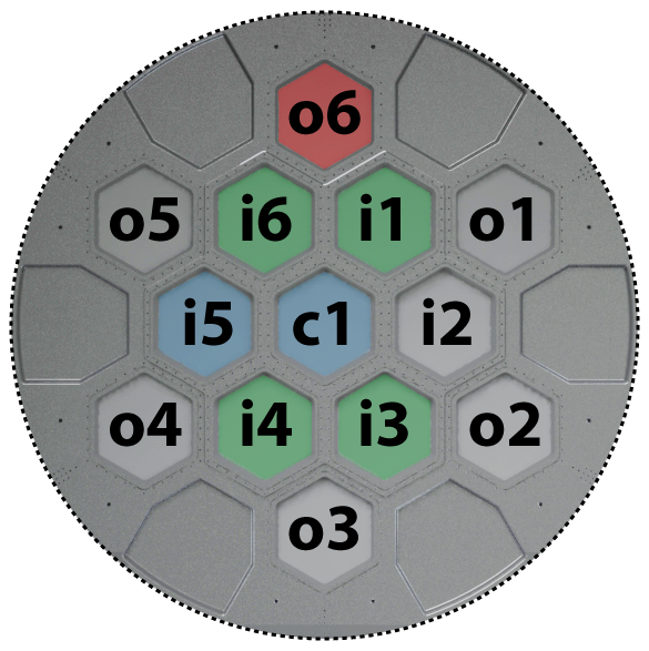
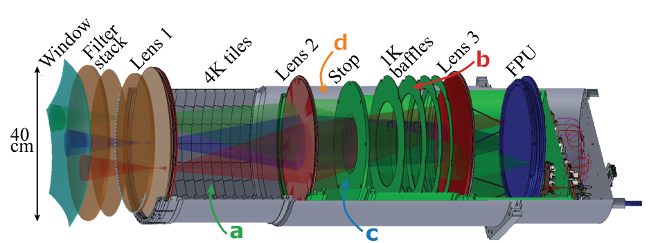
The Simons Observatory’s Large Aperture Telescope is a Crossed-Dragone telescope with an approximately mean entrance pupil diameter and a mean effective focal length of . It shares a common optical and mechanical design with the CCAT-prime telescope and is currently under construction by Vertex Antennentechnik in Germany before transportation and installation at the Simons Observatory site in Chile.111Vertex Antennentechnik GmbH, https://www.vertexant.com/ The Crossed-Dragone design [3, 4, 5, 6, 7] supports large and unblocked optical throughput while meeting the Mizuguchi-Dragone condition [8, 9] to minimize cross-polar response. Additionally, both the primary and secondary mirrors are perturbed from the basic conic sections used in a classic Crossed Dragone telescope design in such a way as to cancel first order coma in off-axis fields. This allows for a diffraction limited field-of-view (FoV) of the telescope of approximately effective diameter at , thus meeting the Simons Observatory’s requirement for optical throughput. A rendering of the telescope with a basic ray-trace is shown in Fig. 1. Figure 2 shows a view of the LAT cryogenic receiver as seen from the secondary mirror with labels for each of the 13 optics tubes. Further details of the optical design can be found in [10, 11]. In general, the optical design is based on work described in [12]. Although all 13 tubes can and have been studied with the analysis tools presented in this paper, our discussion will focus on the optical performance of the center tube and the 6 tubes in the inner circle of the cryogenic receiver (see Fig. 2 and Table 1). We therefore cover the performance of the MF and UHF bands, but do not discuss LF beam performance in this paper.
The primary and secondary mirrors of the Simons Observatory LAT are composed of 77 and 69 individual rectangular panels (Al 5083), respectively, each covering approximately and weighing about . The panels are designed to have a gap at with full gap closure at . Areas surrounding the optically active regions on both the secondary and primary can be lined with panels that would reflect receiver sidelobe power to the sky in order to minimize thermal loading on detectors; we currently have no plans to deploy such panels. For the same reason, however, a roughly 3-m long conical baffle with a 9-deg half opening angle is placed in front of the telescope receiver (see Fig. 1 and Section 4).
The required system half wavefront error (HWFE) is < rms [11]. Contributions to the overall surface HWFE budget for the primary and secondary reflector system have been estimated in several categories, including: a) individual panel manufacturing errors (); b) manufacturing margin on the alignment of the carbon fiber support structures for the primary and secondary mirrors (); c) both types of manufacturing errors, a and b, combined with gravitational deformations (above elevation), wind deformations (up to ), temperature changes and temperature gradients lead to surface error budgets of and for the primary and secondary, respectively. In addition to budget items a-c, we estimate contributions to the HWFE budget from: d) relative alignment between the mirrors under environmental conditions similar to c (); and e) mirror panel alignment errors. Assuming photogrammetry is used to align the mirror panels, the panel alignment errors are estimated to be , which should result in a system HWFE of approximately . If better alignment techniques are used, such as the holography and laser metrology systems planned for CCAT-prime [11], the panel alignment errors could be decreased substantially, potentially decreasing the system HWFE to as low as about . Existing measurements of individual panel surface rms together with engineering models suggest that the HWFE requirement will be met.
As shown in Fig. 1, the two mirrors are mounted in an enclosing elevation structure with the telescope focus outside the rotating housing. The receiver sits on a Nasmyth platform. To reduce systematic effects, such as the change in beam shape with boresight rotation, the receiver is held on a mount designed to co-rotate with the telescope elevation structure. The elevation structure can be pointed from elevation through to on the other side ( throw). The telescope can therefore be pointed straight down in order to protect it from the elements.
2.2 Cold optical design
The cold re-imaging optics that couple detectors to the telescope are shown in Figs. 1 and 3. The design can accommodate 13 optics tube modules, each containing 3 silicon lenses, a filter stack, and, between lenses 2 and 3, a Lyot stop cooled to . The filter stack consists of thin IR blocking filters at cryogenic temperature stages of , , and . Additionally, there is an absorbing alumina filter at and four thicker low pass quasi-optical filters with two at , and one each at , and [13, 14, 15, 16]. Each tube contains either an LF, MF, or UHF focal plane and, other than their meta-material anti-reflective coatings [17], the lens designs do not change between different optics tubes. Apart from optical elements that are obviously frequency dependent (such as bandpass filters), the only optical element that varies between optics tubes is an alumina filter which is given a wedge shape (up to ) in off-center optics tubes in order to make the chief ray of the central field of each tube parallel to the axis of the cryostat. This allows all optics tubes to be telecentric with each other and removes the need for telescope dependent axial shifts. Close packing of the tubes, and hence better use of the focal plane, is achieved with the use of hexagonal vacuum windows; the diameter of these windows is approximately . More details on the cold optical design can be found in [18] and the cryostat in [19].
2.3 Optics tube design
By itself, the cold optical design is relatively simple; a wedged filter, three lenses, and a stop represent the key optical elements in each tube. However, the practical implementation of this design, shown in Fig. 3, is far more complex. The bolometers on the focal plane need to be cooled to in a low magnetic field environment, while the cryogenic cooling at is limited to only tens of microwatts per optics tube. This leads to significant challenges in thermal and magnetic shielding. In particular, great care is needed in the design of the thermal filter stack, including aspects of cutoff frequencies and heatsinking [19]. On top of this, mitigation of stray light is critical — the SO mapping speed is limited in part by thermal loading from the atmosphere as well as loading due to spillover on warm optics. As an example, a one-percent increase in the amount of optical throughput that spills past the warm reflectors (on to ) will reduce the 150-GHz mapping speed by roughly [20]. A considerable effort in reducing warm spillover is therefore warranted. This is the primary goal of the work presented in Sections 3 and 4.
| Frequency | Bands | # Tubes† | # Detectors/tube |
|---|---|---|---|
| LF | 27/ | 1 | 600 |
| MF | 90/ | 4 | 5184 |
| UHF | 220/ | 2 | 5184 |
†Numbers quoted for initial deployment only.
3 Geometric analysis
3.1 Model setup
We used sequential (time-forward) ray tracing in Zemax222Zemax OpticStudio: https://www.zemax.com/products/opticstudio during the original reflector and cold optics design process [10, 18]. While this approach allowed us to optimize the shapes of the lenses and to produce maps of metrics such as the Strehl ratio across the focal planes, this analysis did not account for various optical non-idealities such as stray light (internal reflection) which depends critically on incidence angles. For stray light analysis, we constructed a model of the optics tube including different baffles and anti-reflective coatings using Zemax’s non-sequential mode (Fig. 3). Using this approach, we launched randomly generated (time-reverse) rays from the focal plane and calculated the angular distribution of power emerging from the hexagonal cryostat window to determine spillover past the secondary mirror.
For the three lenses, we assumed coatings representing the thickness, number of layers, and refractive index of the as-machined metamaterial [22, 23]. For all filter surfaces, we assumed coatings on all air transitions. For other surfaces, including the structure of the optics tube and the Lyot stop, we applied coatings that were allowed to vary between absorbing to reflecting. For those surfaces, we studied different types of reflections, including both specular and Lambertian. For each combination of surface type and geometry, we had Zemax launch rays from the focal plane at random angles up to . This angle was chosen to be significantly larger than the acceptance angle of the feeds and lenslets on the focal planes and increasing this angle to made no difference to our results. At each surface, the reflected and refracted paths were calculated and each assigned an appropriate fraction of the power from the incident ray (in accordance with surface properties). These paths were traced until they either hit another surface in the model, they missed all surfaces, exited the cryostat window, or the fraction of power they carried dropped below of the original ray from the focal plane. Increasing this cutoff threshold to made no statistical difference to the output of the simulation. All rays that made it out of the hexagonal vacuum window were then saved to a database. By summing up the power of the rays in this database then, excluding the effects of diffraction which are discussed in Section 5, we can calculate the power exiting the cryostat as a function of angle. This approach also allows us to filter the rays to include those that have (or have not) interacted with different combinations of surfaces, thereby identifying critical areas where the addition of absorbers or changes to geometries are important.
In this analysis, we concentrate on those ray paths that interacted with something other than lenses and filters. More specifically, we focus on rays that interact with: 1) the region between Lenses 1 and 2 at the front of the optics tube; 2) the cold stop surface; and 3) the baffles between the cold stop and Lens 3. Ray paths that have reflections off any pairs of lens or filter surfaces can produce ghost images that contribute to detector sidelobes. However the only thing that can be done about these is to design the best possible anti-reflective coatings (which is already a design goal).
3.2 Modeling absorbers
We want most cavities inside the optics tubes to be black — ideally perfectly absorbing for all incidence angles and frequencies. In the past many different approaches have been used (for a review see [24]) to approximate this condition. At millimeter wavelengths a common approach is to paint surfaces with an epoxy mixed with subwavelength conductive particles such as carbon black for absorption, alumina or fuzed silica frit for coeffienct of thermal expansion (CTE) compensation, and the option of adding scattering centers such as wavelength-sized grains of silicon carbide [25, 26]. Such coatings have the advantage that they are inexpensive, easy to apply to complex shapes, and have a CTE suitably matched to the substrates enabling survival during thermal cycling. For these reasons we adopt this type of absorptive coating as the baseline for all metal surfaces.
Although measurements have shown a very low level of specular reflection () from this coating type, there is a body of evidence that a significant fraction of incident light is scattered [25, 27, 28]. This arises from the (0.5 to 10) wavelength scale roughness of the surface – light which is not absorbed by the coating can be diffusely scattered as well as specularly reflected. For our analysis, a value for this coating of absorbing and scattering was assumed. Although pessimistic for normal incidence, rays reflected at oblique angles could easily be fully polarized. The modelling of the wavelength scale roughness of a typical epoxy coating was not possible within Zemax, so for the epoxy coatings the angle of incidence was ignored. However, for all other surfaces (lenses, filters, bare metal walls, and other types of absorbers) smooth dielectric layers were assumed and polarization taken into account when tracing rays.
Other possible blackening materials include microwave absorbers such as HR10 or TK tiles [29, 30], but these can be harder to apply to curved surfaces such as the inside of the optics tubes and, in the case of HR10, one must contend with fragments of them breaking off. In addition, all absorbers add both weight and cost to the optics tubes. Consequently, the properties of different parts of the optical model were varied between reflecting, absorbing, and scattering. For areas which had little effect on large angle scattered light, we chose to drop the absorbing material (saving cost and weight) while some areas were found to be critical and improvements over the default scattering surface were needed. Flat and angled TK tiles were investigated for areas that needed improvement.
3.3 Results
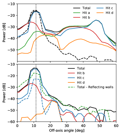
Selected results from our simulations are shown in Figure 4. With the initial simulation using the baseline epoxy coatings, we observe scattered light reaching up to at angles exceeding from the axis to the optics tube. At angles greater than , an azimuthally symmetric sidelobe of only can have a large enough solid angle that, should all power go to 300K, it can easily add a few Kelvin to the detector loading, degrading sensitivity and introducing significant systematic effects, such as cross-polar sidelobe response.
Nearly all the rays that contribute to these sidelobes interact with the front of the optics tube (part in Fig. 3; green line in Fig. 4). Making this area more black is clearly important. A number of possibilities were investigated — there is little room between the mechanical walls of the tube and the optical path, leaving no room for deep baffles. We found various practical issues associated with traditional absorbers such as HR10. Looking at the database of rays scattered from this surface, we see that most rays hit at oblique angles (peaking at from the normal) making most flat absorbers ineffective. We therefore decided on implementing custom angled absorbers.
When the epoxy absorber in these areas was replaced by angled absorbing tiles as shown in Fig. 3 the situation became much better [21]. Such tiles, which are based on the TK tile concept, can be made relatively cheaply and have on their surface tapered spikes on a sub-wavelength scale to act as a broadband AR coating, reducing any reflections. The Zemax modeling shows that these tiles reduce power scattered to wide angles to less than at angles greater than .
Even with these tiles in place, there remains significant power at angles less than — an area which will end up just outside the secondary mirror. Most of this involves a reflection from the edge of the Lyot stop ( in Fig. 3) and then a reflection from one of the many lenses or filters on the sky side of the stop. The original stop was of the classic knife edge design, but close to the center, getting a thick enough layer of absorber without vignetting some of the off-axis fields was challenging. By removing all absorber and making the inner surface reflecting but at from the axis of the tube, this power is instead redirected to the tube where it is absorbed. Further from the center of the stop, black absorbing TK tiles can be placed.
With the above two changes, simulations predict the dashed blue line at the bottom of Fig. 4. As an experiment, we tested making the walls and baffles ( and in Fig. 3) reflective. Although an increase in the scattered light is clearly visible (the dashed green line), the increase is small. If the baffles are left with epoxy absorber and only the walls of the tube made reflective, very little increase in the scattered light could be seen. This represented a considerable reduction in mass, and so this design has been adopted for the Simons Observatory LAT optics tubes.
If the assumptions used to generate these simulations are valid, then secondary spillover from the cold optics will be less than of the total optical throughput. However, it is quite possible that these simulations are missing important internal reflection mechanisms. Therefore, strategies to mitigate unexpected spillover from the cold optics are discussed next.
4 Spillover and far sidelobes predictions
The cold optics tube design of the ACTpol experiment, which includes three lenses with an intermediate primary image Lyot stop, is similar in many ways to the one adopted for the Simons Observatory [31]. Analysis comparable to the one described in the preceding section was performed for ACTpol, and that analysis suggested an acceptably low level of sidelobes from the cold optics tube. However, in-situ near-field measurements of the ACTpol optics tubes show a much higher level of scattered and/or diffracted light at large angles [32], possibly due to an excess reflectivity in baffling materials inside the camera. In this section, we take this measured optics tube spillover as a worst case scenario and use it to inform the design of an additional baffle that can be installed inside the SO elevation structure.
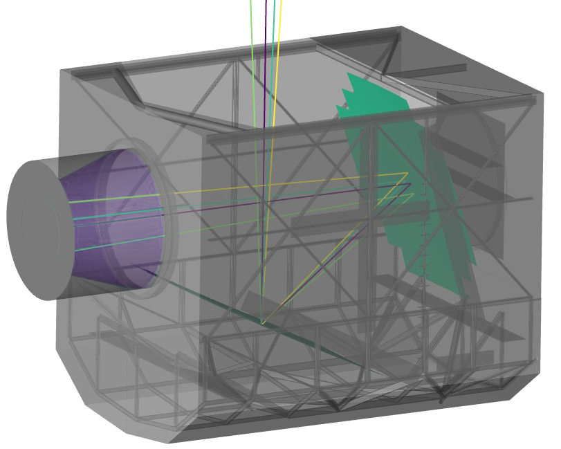
During the design stages of SO LAT, we studied geometrical mitigation strategies to (in a time-reverse sense) direct as much radiation from the optics tubes to the sky as quickly as possible (i.e., with the lowest number of bounces). We use a source with a beam given by an analytic model, placed at the secondary focus and oriented parallel to the chief ray (see Fig. 5). This beam causes roughly of the total optical power to spill past the secondary mirror (see Eq. 1 and Fig. 4 in [32]). The model is purely phenomenological and does not impose restrictions on the physical origin of spilled light. The model is composed of a central Gaussian beam and an exponential fall-off tail (for the analytic description, see Table 1 in [32]). A non-sequential time-reverse ray trace that incorporates a preliminary 3D solid model of the warm optics (see Fig. 5) is used to compute the sky illumination pattern caused by interactions with the telescope structure. We treat all surfaces in the elevation structure as reflectors with a loss. This simulation was implemented in Zemax in non-sequential mode and only considers unpolarized light; we leave polarization as future work. Further details of this ray tracing analysis will be presented in a future work.
The optimization of the warm structure was done in successive iterations as the mechanical design converged. We tested the benefit of using guard rings around the warm mirrors and found that the benefit would be marginal compared to the cost. Despite this, we installed mounting points to allow a later addition if deemed necessary. From this analysis, we concluded that apertures inside the elevation structure (like the elevation bearing or the entrance aperture on the top of the structure) should be made as large as possible to allow light to escape the housing with a minimum number of reflections.
We also implemented a receiver baffle surrounding the camera entrance apertures to direct stray light from the receiver to the sky. We considered two design options for this purpose, a truncated paraboloid with a focal point at the midpoint of the receiver entrance and a simpler conical shape. The paraboloid configuration was shown to perform best for rays placed at the center of the secondary focal plane, but after accounting for proper geometrical weighting of the entire secondary focal plane, the simpler conical shape performs better. The conical design is also less expensive and more mechanically robust. The conical baffle (shown in Fig. 5) covers all the available space in the receiver cabin to smoothly transition the aperture size to the elevation housing.
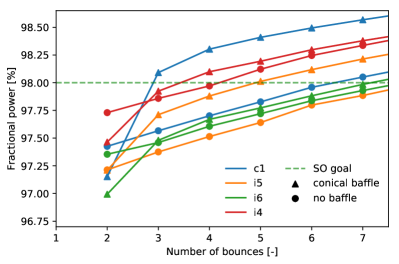
Figure 6 shows the fraction of optical power that makes it to the sky as a function of the number of ray tracing bounces. For all field locations considered, the nominal path (2 bounces) gets 97.0– of the power to the sky. For the model that includes the receiver baffle, there is a significant increase seen in the amount of power that makes it to the sky between 2 and 3 jumps. It is estimated that this baffle can boost the fraction of light making it to the sky by as much as 0.5 of the total input optical power (depending on the field location), which would have an impact of roughly 10- in mapping speed at MF frequencies [20], at the expense of having a circularly symmetric sidelobe at 7–8 degrees from the main beam.
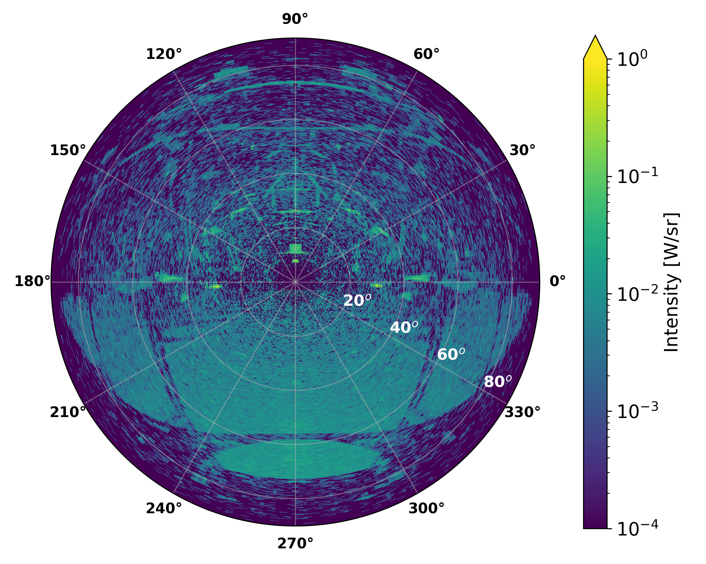
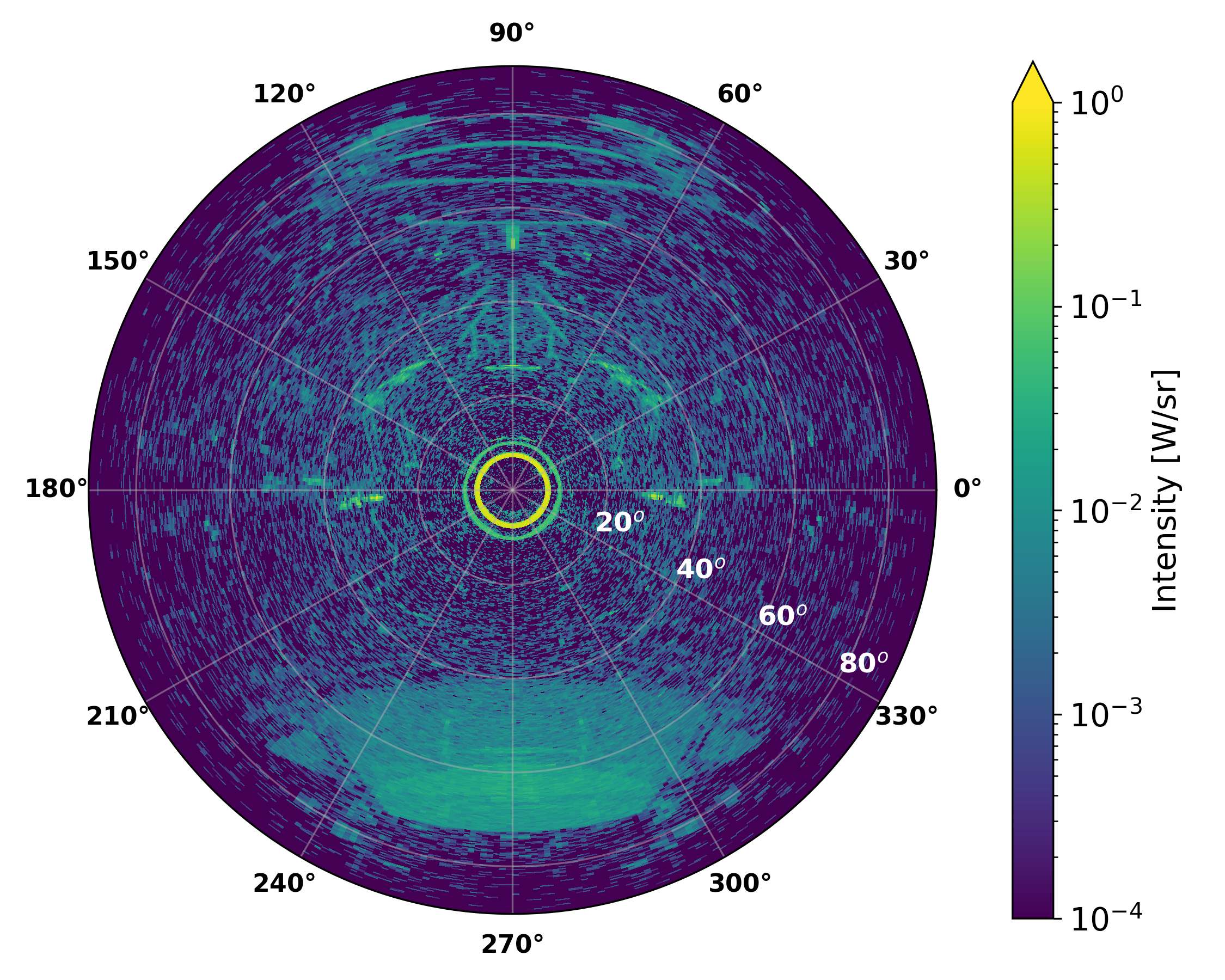
Figure 7 summarizes the results of our ray tracing simulations for the conical baffle. In general, this conical baffle design suppresses very large angle sidelobes, giving them a more central and azimuthally symmetric distribution on the sky. Of particular interest is an extended feature centered around the azimuthal coordinate. This feature is due to direct illumination of the elevation housing aperture from the source location at the receiver vacuum windows. For the case of the central field location, which is shown in Fig. 7, we find that the amount of power in this large sidelobe pattern is reduced by a factor of 1.6, going from 1.00 to of the total beam power. The extended sidelobe is replaced by an annular feature that spans roughly 7– and contains approximately of the total power that makes it to the sky. If this model is accurate, we will be able to measure, avoid in observation-time and correct for this feature in analysis. It is also worth emphasizing that the assumption of secondary spillover is likely pessimistic given the research and development on internal baffling [21].
5 Physical optics
5.1 Basic model setup
Physical optics simulations allow us to calculate the frequency dependent beam response, including diffraction effects, in both the near- and far-field. Using this technique, we can predict the nominal beam response for the different frequency bands in the SO LAT. W e generate an ensemble of physical optics simulations using an application programming interface (API) that couples to TICRA Tools (formerly GRASP) [33]; a similar approach was described in [34, 35].333See https://www.ticra.com/ The physical optics simulations are carried out in a time-reverse sense (transmit) and start with the generation of outward propagating electric field at the location of the focal plane. The field is then propagated through all three lenses of each optics tube as well as the cold stop. The field from lens 1 is then used to calculate the field distribution on the hexagonal vacuum window (see Fig. 3) which is in turn used to predict the field at the secondary and primary mirrors and then into the far-field.
The optically active region of the secondary and primary mirrors are input to these simulations in the form of a tabulated mesh sampled at 1-cm intervals. Within TICRA Tools, the regions are defined as ellipses with 6003- and geometrical mean diameters for the secondary and primary, respectively. This implies that the TICRA tools models extend beyond both the optically active area of the mirrors as defined by geometrical optics and the as-built reflectors which are composed of a total of 146 rectangular panels (see Fig. 1). As a result, the predicted far-field beam maps will not capture diffraction effects from truncated field distributions caused by the discrete panel distributions; this will likely affect the predicted beam size at the percent-level. The tabulated mesh of the elliptical reflector shapes are resampled by TICRA Tools at the lowest resolution required to be accurate down to compared to peak main beam response. Similarly, the surfaces on each side of the three lenses as well as the hexagonal vacuum window are meshed at the resolution that is sufficient for convergence of the far-field beam maps.
The physical optics simulations do not account for internal reflections in the lenses or any back scattering because of limitations in simulations of anti-reflection coatings. Similarly, the simulations do not account for interactions with absorbing elements along the sides of the cooled optics tubes nor do they account for in-band scattering from filters or (lens/reflector) surface irregularities. Finally, effects from interactions with the telescope housing structure or its aperture is not included in the physical optics simulations described below. The two reflectors incorporated in these physical optics simulations are a single-body object with an elliptical rim; the effects of the 146 panels that make up the mirrors, as well as the gaps between them, are not included in these simulations. All of these simplifying assumptions are made to facilitate practical computation times. With this in mind, it is clear that the simulation results describe theoretical best-case scenarios given the proposed telescope geometry and predicted detector far-field beam. We have not conducted tolerancing analysis using physical optics, therefore we do not have means to quantify the expected deviations from mechanical errors and deformations in optical elements. However, past experience from the Atacama Cosmology Telescope (ACT) indicates that for the MF frequency bands we can expect a 5- increase in realized beam FWHM compared to naive predictions [36]. From simply comparing the Strehl ratio distributions for ACT and SO LAT at MF frequencies, we would expect SO LAT to perform somewhat better.
We note that it is possible to run physical optics simulations that account for the finite conductivity of the aluminum panels. For a select number of detectors we have run simulations that assume a finite conductivity of for both the secondary and primary mirrors. However, we find that the impact on both the estimated beam FWHM and ellipticity is negligible, and therefore we have not included it in our general simulations as it adds significantly to the computation time.
During nominal operations, the scan-averaged telescope elevation is approximately . As the telescope changes elevation angles, the LATR will co-rotate so as to keep the illumination pattern of the optics constant on the secondary. The clocking of the LATR will also be configured for optimal cryogenic performance. This implies an orientation in which the LATR dilution refrigerator is oriented at 12 o’clock (pointed up) as seen from the center of the secondary mirror while the telescope is pointed at elevation. If the elevation housing rotates while the LATR is fixed, we expect some changes in the beam response. The physical optics simulations described in this section correspond to a LATR orientation where the dilution refrigerator has been rotated from its nominal configuration. This happens to be the configuration that yields the highest band-average Strehl numbers. We have performed PO simulations to compare the expected far field beams for these two configurations. Basic far field beam properties such as FWHM and ellipticities are found to be consistent within 1-. Initial optimization of the LAT scan strategy can be found in [37]. Further details will be described in future publications.
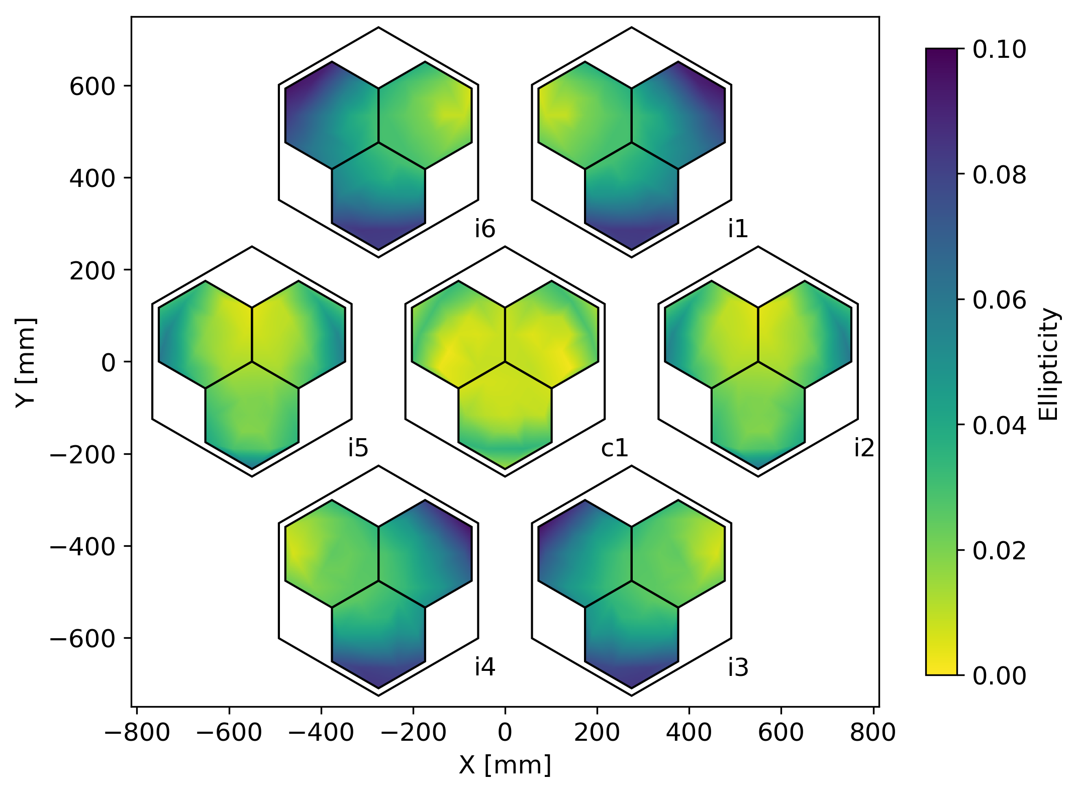
To map out beam properties across the focal plane, we run physical optics simulations where the source is placed at 52 distinct FPU locations within each optics tube. Because of symmetry, we only consider tubes c, i5, i6, and i4 (see Fig. 1). The results of these simulations are analyzed to estimate beam properties such as beam width, ellipticity, and cross-polar response. These properties are then input to a bi-linear interpolation routine, scipy.interpolate.griddata, to estimate the distribution across the entire focal plane (see the following sub-sections).
5.2 Pixel beam model
The MF receivers will employ spline-profiled feedhorn arrays which are machined out of aluminum and then gold plated [38, 39]. A waveguide section of the feedhorns then couples the incoming radiation to bolometer arrays [40]. The feedhorns have apertures and wall thickness between feeds. These produce roughly and cold stop edge tapers at 90 and , respectively. Simulations of feedhorn optical response are performed using Ansys HFSS. During the feedhorn design process, requirements of the far-field pixel beam symmetry was relaxed in order to increase optical throughput. The output of the HFSS simulations is used as input to the TICRA Tools physical optics simulations. For simplicity, the input pixel beams are perfectly polarized so that any cross-polar far-field response will be indicative of optical effects and non-idealities outside of the pixels. The simulations results represent the monochromatic beam at the specified frequencies.
5.3 Beam size and ellipticity
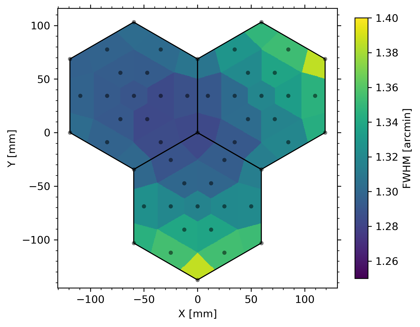
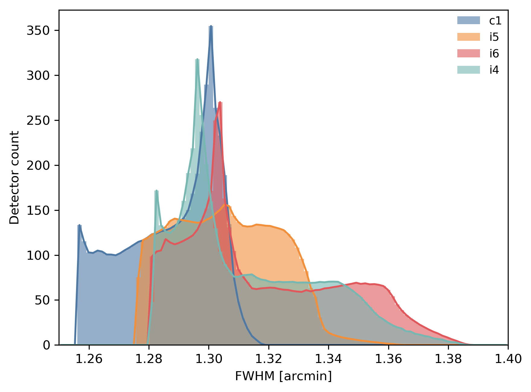
Beam size and symmetry impact the science goals of the LAT. We use the physical optics simulation results to estimate these properties for the telescope under nearly ideal circumstances. The results from these simulations are summarized in Fig. 8-9 and Table 2. As expected, both the beam size and ellipticity grow as one moves away from the center optics tube. We define the beam full width at half maximum (FWHM) as the geometrical mean of the FWHM for the major and minor axis of the best fit elliptical Gaussian model. The beam ellipticity is defined as
| (1) |
where and correspond to the widths of the best-fit Gaussian envelope to the major and minor axis of the co-polarized far-field beam response. The beam FWHM, , is related to and according to:
| (2) |
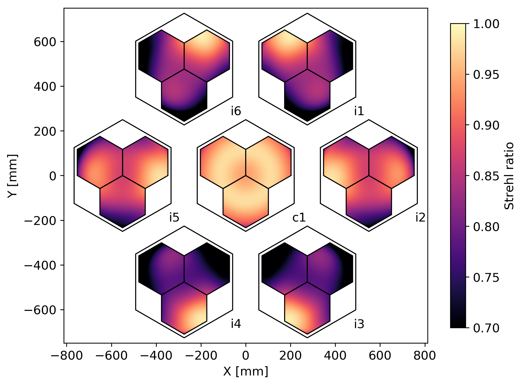
Assuming a primary aperture illumination, the beam sizes are predicted to stay within roughly 5- of the diffraction limit at 90 and , respectively (see Table 2). The deviation from the theoretical best-case scenario is primarily due to non-uniform aperture illumination. As expected, the center optics tube shows the best optical performance and there is strong correlation between beam size and Strehl ratio.
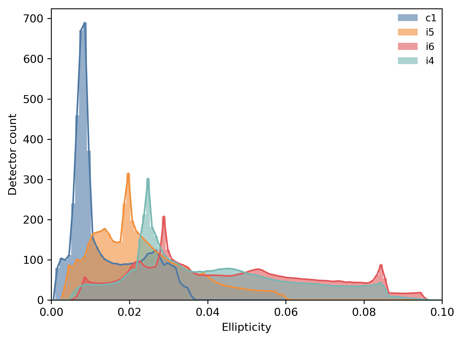
For the most part, beam ellipticity is found to correlate strongly with Strehl ratio as calculated using Zemax. This of course implies that the beams get more elliptical (on average) with increasing frequency. However, since the Strehl ratio statistics assume uniform aperture sampling instead of applying weights that represent the profile of the feedhorns, we do not expect perfect correlation between the beams predicted by these physical optics simulations and the quoted Strehl ratios. Fig. 10 shows the distribution of beam ellipticity across the seven optics tubes. For comparison, the Strehl ratio distributions are also shown. From these simulations at 90 and , we observe that the orientation of the semi-minor and semi-major axis of the best-fit elliptical beam is strongly correlated with the projected aperture of the primary and secondary mirrors and less dependent on the illumination profile of the cold stop.
5.4 Cross-polarization
Cross-polar response is known to be minimal for Crossed-Dragone telescope designs [8, 9]. However, because of off-axis pixels (which break the Mizuguchi-Dragone condition), finite reflector conductivity, and other non-idealities, some level of cross-polar response is unavoidable. The physical optics simulations allow us to estimate cross-polar response caused by geometrical effects and finite conductivity. We calculate the far-field Stokes , , and beams from the complex electric fields output by the TICRA Tools simulations. Since the pixel beam input to our simulation is perfectly polarized, the Stokes beam is very similar to the Stokes beam. The beam map, on the other hand, has a typical quadrupolar shape with alternating positive and negative lobes. After accounting for polarization angle rotation, so as to minimize the solid angle in the beam, we calculate the peak ratio of at the map level. This number gives an indication of the level of cross-polarization that is expected from the optical system alone. Note that this does not incorporate the cross-polar response from the feedhorns or from inductive coupling in the readout electronics. At 90 and , we find that the peak amplitude in the beam map ranges from to with the lowest values registering at the center of each focal plane.
| Freq. | Tube | FWHM | Ellipticity |
|---|---|---|---|
| [GHz ] | [arcmin] | [-] | |
| 90 | c | ||
| 90 | i5 | ||
| 90 | i6 | ||
| 90 | i4 | ||
| 150 | c | ||
| 150 | i5 | ||
| 150 | i6 | ||
| 150 | i4 | ||
| 220 | c | ||
| 220 | i5 | ||
| 270 | c | ||
| 270 | i5 |
5.5 Cold spillover results
With the pixel beam models as input, the physical optics simulations can be used to keep track of how much power spills past a given optical element. These calculations therefore allow us to estimate the total optical spillover inside the optics tube as well as the spillover past the two reflectors. As discussed in Sections 3 and 4, spillover influences the optical performance and mapping speed of the telescope.
The non-sequential ray tracing enables fast mitigation of spurious rays and therefore sheds light on both systematic and noise performance; this approach is also the only viable option for electrically large objects like the LAT telescope housing. On the other hand, a physical optics analysis quantifies nominal spillover performance expected from a perfect realization of a proposed design. Using a programming interface to TICRA Tools, we can run spillover analysis as a function of focal plane location. This approach also expands and improves on the Gaussian beam formalism that is frequently used (see e.g. [41]).
Unfortunately, the physical optics spillover calculations require a higher degree of convergence and therefore higher resolution meshing compared to those needed to estimate the far-field beam response. Because these are more time consuming, we are not able to run spillover simulations for dozens of detectors in each of the different optics tubes. We also choose not to focus on these reflector spillover statistics, since near field sidelobe estimates, for example from in-band scattering on filters or internal reflection on both active and passive optical elements inside the tube, have considerable uncertainties. In order to generate spillover estimates at a given frequency, we have run simulations at only seven points along a radial line from the center of the focal plane to the edge. Internally to the optics tubes, the total spillover past a given optical element is azimuthally symmetric. From these seven physical optics simulations we can estimate the spillover at any given location on the focal plane through interpolation.
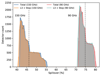
Figure 11 shows a histogram of total optical spillover internal to the tube. The steps are largely caused by the radial pixel distributions for the three hexagonal tile arrangement. At we note that the cold spillover can vary by up to depending on focal plane location, but only by about at . As expected, the majority of the cold spillover happens at or before the cold stop. However, percent-level spillover past lens 1 and lens 2 is also observed in some cases, which is manifest in the slight shift of the total spillover distributions relative to the “L3 + Stop” distribution. It is interesting to note that approximately of the pixel beam spills on the walls of the cryogenic receiver (past the stop).
5.6 Frequency and focal plane statistics
6 Panel gaps effect
The primary and secondary mirrors are composed of 69 and 77 rectangular panels, respectively. The primary panels are mm, while the secondary are mm. They are arranged in a square array, with a nominal gap of between adjacent panels when the mirrors are at a temperature of . These discontinuities in the reflector surface are expected to induce features in the far-field beam patterns. To quantify this, we employed a TICRA Tools physical optics analysis method which defines the reflectors as multi-face objects. Each panel is individually defined by a rim placed on the tabulated mesh described in Section 5. The far-field beam map is computed on a degree elevation-over-azimuth grid. The source that illuminates the secondary is placed at the center of the central optical tube. This source illuminates the secondary mirror using a 90- or a near-field beam pattern which is based on the PO model of the receivers described in Section 5. This is done to simulate the tapered illumination at the nominal rim of the mirrors.
This model does not factor in scattering from the aperture of the elevation housing, which will likely impact far-sidelobes. However, the purpose of this study is to gauge the expected amplitude and angular shape of panel-gap diffraction lobes. A more advanced model that incorporates the shutter aperture is left for future work.
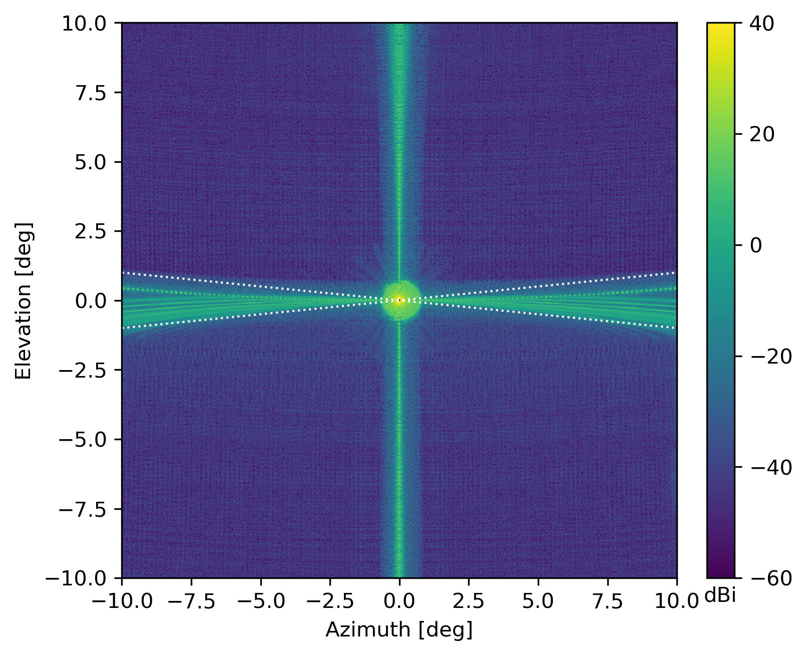
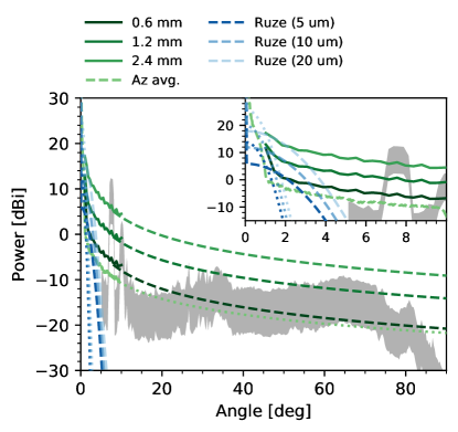
Figure 12 shows the predicted far-field beam map at . Diffraction from panel gaps produces an extended cross-shaped pattern with an approximate amplitude of at angle away from the beam center which decreases gradually (see Figure 13). Although the feature is quite pronounced in the beam map, the fractional beam solid angle outside a 1-degree radius from the main beam centroid is less than of the total predicted at both 90 and . The amplitude of this diffraction feature is of course frequency dependent, the average beam profile amplitude in the 2- region is 1.0 and at 90 and , respectively. In contrast, the azimuthally averaged beam profiles in that same angular region have a mean of -9.3 and for 90 and , respectively; significantly smaller than the cross-shaped diffraction features. The forward gain of a 90 and pixel are predicted to be roughly 73.6 and at 90 and , respectively. The expected beam profile amplitude from Ruze scattering [42], assuming correlation length and 5- RMS error, is smaller than the azimuthally-averaged beam profiles predicted by these PO simulations at angles greater than .
It is interesting to study the scaling of this panel-gap diffraction pattern with both frequency and panel separation. For this purpose, we have run these simulations using three values for panel gap separation corresponding to 0.6, 1.2 (nominal), and . Those simulations suggest that the amplitude of the beam sidelobes caused by panel gap diffraction depends on the physical separation between segments, as expected. For example, at 150 GHz, the predicted sidelobe amplitude at is -3.4, 2.6, for 0.6, 1.2, and , respectively. Figure 13 compares the panel gap diffraction beam profiles to that of the Ruze envelope for a single mirror with 2- and correlation length and a surface RMS of 5, 10, and . It is clear that the Ruze envelope model is unable to produce extended high amplitude sidelobes that are comparable to the panel gap diffraction pattern using correlation lengths and RMS errors that are consistent with existing panel surface RMS measurements (see Section 2). We note that panel misalignment errors will most likely be driven by correlation lengths that are comparable or a factor of few smaller than the panel dimensions and that these deformations will be dominated by thermal and gravitational effects [11].
Figure 13 also compares the panel gap diffraction results to the predictions of the ray tracing spillover analysis presented in Section 4. It is important to note that neither the spillover sidelobes nor the sidelobes from panel gap diffraction are expected to be azimuthally symmetric. Therefore, comparison of beam profiles as presented in Figure 13 only captures the relative power of these two effects after applying an azimuthal average. The sidelobe response will be dominated by different optical effects depending on both the radial and azimuthal sky-location relative to the beam centroid.
7 Conclusions
We have presented a suite of geometrical and physical optics simulations that shed light on the SO LAT optical design and some of its associated systematics. The simulation framework has informed all aspects of the optical design and we expect that the tools have been developed will also play a crucial role in assessing initial system performance when the telescope becomes operational.
Through non-sequential ray tracing we have confirmed that absorbing material should be prioritized near the front (sky side) of the optics tubes. Non-sequential ray tracing has also shown that a simple conical baffle mounted in front of the telescope receiver helps direct near field sidelobes to the sky as quickly as possible and therefore minimizes loading from the elevation housing. This analysis showed that little was gained from a more complex (and costly) parabolic baffle design. This additional baffle directs rays that would otherwise be distributed asymmetrically over wide angles to a more azimuthally symmetric pattern at roughly 7- from the main beam.
We show results from physical optics simulations that suggest relatively compact and symmetric far field beams will be achieved. As expected, the physical optics simulations correlate significantly with Strehl ratio calculations from ray tracing. The physical optics calculations also show how the cold optics spillover is expected to vary across the focal plane under ideal conditions. Finally, we present physical optics simulations that address diffraction effects from panel gaps. These simulations show how the amplitude of the panel gap sidelobes is expected to change with frequency and panel gap separation.
The shape of the far field beam maps of the Simons Observatory Small and Large Aperture telescopes impact all astrophysical and cosmological analysis made by the experiment. In general, the non-symmetric part of a beam response can couple parity even and parity odd polarization modes on the sky and therefore complicate the interpretation of Stokes and sky maps. For the SO LAT, beam asymmetries can impact the shape reconstruction of both the CMB lensing potential and extended objects such as galaxy clusters. Simulation work that sheds light on the impact of beam non-idealities is currently in progress and will be discussed in future publications. The extensive simulation capabilities that we have developed allow us to model the as-built instrument and compare the expected and realized signal response, which will continue to aid in optimizing the observatory performance over time.
Throughout the SO LAT design process we have tried to optimize for both beam symmetry and forward gain. We have also explored how several factors contribute to beam spillover and affect the mapping speed of the instrument by coupling the detectors to unwanted radiation sources, such as the inside of the telescope structure, a distant mountain, or the moon. Measurements of spillover and scattering from instrument optics (lenses, filters, and baffles) are now getting underway; this will enable initial model comparisons. Once the instrument is deployed on the telescope, one of the first goals will be to test these predictions under a wide range of conditions through observations of point sources such as planets. These results will later be used for calibration and to aid with interpretation of the first cosmological measurements with the SO LAT.
8 Funding Information
This work was supported in part by a grant from the Simons Foundation (Award #457687, B.K.). JEG acknowledges support from the Swedish National Space Agency (SNSA/Rymdstyrelsen) and the Swedish Research Council (Reg. no. 2019-03959). GEC acknowledges support from NSF GRFP. MD thanks the Simons Observatory and The University of Pennsylvania. RD thanks CONICYT for grant BASAL CATA AFB-170002. GF acknowledges support from the European Research Council under the European Union’s Seventh Framework Programme (FP/2007-2013) / ERC Grant Agreement No. [616170], and support by the UK STFC grants ST/T000473/1. FM acknowledges the support from the World Premier International Research Center Initiative (WPI), MEXT, Japan. PDM contribution is supported by the Simons Observatory and funds from the Arizona State University Interplanetary Initiative. KM acknowledges support from the National Research Foundation of South Africa. MDN acknowledges support from NSF award AST-1454881. This manuscript has been authored by Fermi Research Alliance, LLC under Contract No. DE-AC02-07CH11359 with the U.S. Department of Energy, Office of Science, Office of High Energy Physics.
9 Disclosures
The authors declare no conflicts of interest.
References
- [1] N. Galitzki, A. Ali, K. S. Arnold, P. C. Ashton, J. E. Austermann, C. Baccigalupi, T. Baildon, D. Barron, J. A. Beall, S. Beckman, S. M. M. Bruno, S. Bryan, P. G. Calisse, G. E. Chesmore, Y. Chinone, S. K. Choi, G. Coppi, K. D. Crowley, K. T. Crowley, A. Cukierman, M. J. Devlin, S. Dicker, B. Dober, S. M. Duff, J. Dunkley, G. Fabbian, P. A. Gallardo, M. Gerbino, N. Goeckner-Wald, J. E. Golec, J. E. Gudmundsson, E. E. Healy, S. Henderson, C. A. Hill, G. C. Hilton, S.-P. P. Ho, L. A. Howe, J. Hubmayr, O. Jeong, B. Keating, B. J. Koopman, K. Kiuchi, A. Kusaka, J. Lashner, A. T. Lee, Y. Li, M. Limon, M. Lungu, F. Matsuda, P. D. Mauskopf, A. J. May, N. McCallum, J. McMahon, F. Nati, M. D. Niemack, J. L. Orlowski-Scherer, S. C. Parshley, L. Piccirillo, M. Sathyanarayana Rao, C. Raum, M. Salatino, J. S. Seibert, C. Sierra, M. Silva-Feaver, S. M. Simon, S. T. Staggs, J. R. Stevens, A. Suzuki, G. Teply, R. Thornton, C. Tsai, J. N. Ullom, E. M. Vavagiakis, M. R. Vissers, B. Westbrook, E. J. Wollack, Z. Xu, and N. Zhu, “The Simons Observatory: Instrument Overview,” in Proc. SPIE, , vol. 10708 of Society of Photo-Optical Instrumentation Engineers (SPIE) Conference Series (2018), p. 1070804.
- [2] P. Ade, J. Aguirre, Z. Ahmed, S. Aiola, A. Ali, D. Alonso, M. A. Alvarez, K. Arnold, P. Ashton, J. Austermann, H. Awan, C. Baccigalupi, T. Baildon, D. Barron, N. Battaglia, R. Battye, E. Baxter, A. Bazarko, J. A. Beall, R. Bean, D. Beck, S. Beckman, B. Beringue, F. Bianchini, S. Boada, D. Boettger, J. R. Bond, J. Borrill, M. L. Brown, S. M. Bruno, S. Bryan, E. Calabrese, V. Calafut, P. Calisse, J. Carron, A. Challinor, G. Chesmore, Y. Chinone, J. Chluba, H.-M. S. Cho, S. Choi, G. Coppi, N. F. Cothard, K. Coughlin, D. Crichton, K. D. Crowley, K. T. Crowley, A. Cukierman, J. M. D’Ewart, R. Dünner, T. de Haan, M. Devlin, S. Dicker, J. Didier, M. Dobbs, B. Dober, C. J. Duell, S. Duff, A. Duivenvoorden, J. Dunkley, J. Dusatko, J. Errard, G. Fabbian, S. Feeney, S. Ferraro, P. Fluxà, K. Freese, J. C. Frisch, A. Frolov, G. Fuller, B. Fuzia, N. Galitzki, P. A. Gallardo, J. Tomas Galvez Ghersi, J. Gao, E. Gawiser, M. Gerbino, V. Gluscevic, N. Goeckner-Wald, J. Golec, S. Gordon, M. Gralla, D. Green, A. Grigorian, J. Groh, C. Groppi, Y. Guan, J. E. Gudmundsson, D. Han, P. Hargrave, M. Hasegawa, M. Hasselfield, M. Hattori, V. Haynes, M. Hazumi, Y. He, E. Healy, S. W. Henderson, C. Hervias-Caimapo, C. A. Hill, J. C. Hill, G. Hilton, M. Hilton, A. D. Hincks, G. Hinshaw, R. Hložek, S. Ho, S.-P. P. Ho, L. Howe, Z. Huang, J. Hubmayr, K. Huffenberger, J. P. Hughes, A. Ijjas, M. Ikape, K. Irwin, A. H. Jaffe, B. Jain, O. Jeong, D. Kaneko, E. D. Karpel, N. Katayama, B. Keating, S. S. Kernasovskiy, R. Keskitalo, T. Kisner, K. Kiuchi, J. Klein, K. Knowles, B. Koopman, A. Kosowsky, N. Krachmalnicoff, S. E. Kuenstner, C.-L. Kuo, A. Kusaka, J. Lashner, A. Lee, E. Lee, D. Leon, J. S. Y. Leung, A. Lewis, Y. Li, Z. Li, M. Limon, E. Linder, C. Lopez-Caraballo, T. Louis, L. Lowry, M. Lungu, M. Madhavacheril, D. Mak, F. Maldonado, H. Mani, B. Mates, F. Matsuda, L. Maurin, P. Mauskopf, A. May, N. McCallum, C. McKenney, J. McMahon, P. D. Meerburg, J. Meyers, A. Miller, M. Mirmelstein, K. Moodley, M. Munchmeyer, C. Munson, S. Naess, F. Nati, M. Navaroli, L. Newburgh, H. N. Nguyen, M. Niemack, H. Nishino, J. Orlowski-Scherer, L. Page, B. Partridge, J. Peloton, F. Perrotta, L. Piccirillo, G. Pisano, D. Poletti, R. Puddu, G. Puglisi, C. Raum, C. L. Reichardt, M. Remazeilles, Y. Rephaeli, D. Riechers, F. Rojas, A. Roy, S. Sadeh, Y. Sakurai, M. Salatino, M. Sathyanarayana Rao, E. Schaan, M. Schmittfull, N. Sehgal, J. Seibert, U. Seljak, B. Sherwin, M. Shimon, C. Sierra, J. Sievers, P. Sikhosana, M. Silva-Feaver, S. M. Simon, A. Sinclair, P. Siritanasak, K. Smith, S. R. Smith, D. Spergel, S. T. Staggs, G. Stein, J. R. Stevens, R. Stompor, A. Suzuki, O. Tajima, S. Takakura, G. Teply, D. B. Thomas, B. Thorne, R. Thornton, H. Trac, C. Tsai, C. Tucker, J. Ullom, S. Vagnozzi, A. van Engelen, J. Van Lanen, D. D. Van Winkle, E. M. Vavagiakis, C. Vergès, M. Vissers, K. Wagoner, S. Walker, J. Ward, B. Westbrook, N. Whitehorn, J. Williams, J. Williams, E. J. Wollack, Z. Xu, B. Yu, C. Yu, F. Zago, H. Zhang, N. Zhu, and Simons Observatory Collaboration, “The Simons Observatory: science goals and forecasts,” \JournalTitleJ. Cosmology Astropart. Phys. 2019, 056 (2019).
- [3] P. K. Grimes, P. A. R. Ade, M. D. Audley, C. Baines, R. A. Battye, M. L. Brown, P. Cabella, P. G. Calisse, A. D. Challinor, P. J. Diamond, W. D. Duncan, P. Ferreira, W. K. Gear, D. Glowacka, D. J. Goldie, W. F. Grainger, M. Halpern, P. Hargrave, V. Haynes, G. C. Hilton, K. D. Irwin, B. R. Johnson, M. E. Jones, A. N. Lasenby, P. J. Leahy, J. Leech, S. Lewis, B. Maffei, L. Martinis, P. Mauskopf, S. J. Melhuish, C. E. North, D. O’Dea, S. M. Parsley, L. Piccirillo, G. Pisano, C. D. Reintsema, G. Savini, R. Sudiwala, D. Sutton, A. C. Taylor, G. Teleberg, D. Titterington, V. Tsaneva, C. Tucker, R. Watson, S. Withington, G. Yassin, J. Zhang, and J. Zuntz, “Clover - Measuring the Cosmic Microwave Background B-mode Polarization,” in Twentieth International Symposium on Space Terahertz Technology, E. Bryerton, A. Kerr, and A. Lichtenberger, eds. (2009), p. 97.
- [4] C. Bischoff, A. Brizius, I. Buder, Y. Chinone, K. Cleary, R. N. Dumoulin, A. Kusaka, R. Monsalve, S. K. Næss, L. B. Newburgh, G. Nixon, R. Reeves, K. M. Smith, K. Vanderlinde, I. K. Wehus, M. Bogdan, R. Bustos, S. E. Church, R. Davis, C. Dickinson, H. K. Eriksen, T. Gaier, J. O. Gundersen, M. Hasegawa, M. Hazumi, C. Holler, K. M. Huffenberger, W. A. Imbriale, K. Ishidoshiro, M. E. Jones, P. Kangaslahti, D. J. Kapner, C. R. Lawrence, E. M. Leitch, M. Limon, J. J. McMahon, A. D. Miller, M. Nagai, H. Nguyen, T. J. Pearson, L. Piccirillo, S. J. E. Radford, A. C. S. Readhead, J. L. Richards, D. Samtleben, M. Seiffert, M. C. Shepherd, S. T. Staggs, O. Tajima, K. L. Thompson, R. Williamson, B. Winstein, E. J. Wollack, and J. T. L. Zwart, “The Q/U Imaging ExperimenT Instrument,” \JournalTitleApJ 768, 9 (2013).
- [5] T. Essinger-Hileman, J. W. Appel, J. A. Beall, H. M. Cho, J. Fowler, M. Halpern, M. Hasselfield, K. D. Irwin, T. A. Marriage, M. D. Niemack, L. Page, L. P. Parker, S. Pufu, S. T. Staggs, O. Stryzak, C. Visnjic, K. W. Yoon, and Y. Zhao, “The Atacama B-Mode Search: CMB Polarimetry with Transition-Edge-Sensor Bolometers,” in Low Temperature Detectors - AIP Conference Proceedings, , vol. 1185 (2010), pp. 494–97.
- [6] H. Sugai, P. A. R. Ade, Y. Akiba, D. Alonso, K. Arnold, J. Aumont, J. Austermann, C. Baccigalupi, A. J. Banday, R. Banerji, R. B. Barreiro, S. Basak, J. Beall, S. Beckman, M. Bersanelli, J. Borrill, F. Boulanger, M. L. Brown, M. Bucher, A. Buzzelli, E. Calabrese, F. J. Casas, A. Challinor, V. Chan, Y. Chinone, J. F. Cliche, F. Columbro, A. Cukierman, D. Curtis, P. Danto, P. de Bernardis, T. de Haan, M. De Petris, C. Dickinson, M. Dobbs, T. Dotani, L. Duband, A. Ducout, S. Duff, A. Duivenvoorden, J. M. Duval, K. Ebisawa, T. Elleflot, H. Enokida, H. K. Eriksen, J. Errard, T. Essinger-Hileman, F. Finelli, R. Flauger, C. Franceschet, U. Fuskeland , K. Ganga, J. R. Gao, R. Génova-Santos, T. Ghigna, A. Gomez, M. L. Gradziel, J. Grain, F. Grupp, A. Gruppuso, J. E. Gudmundsson, N. W. Halverson, P. Hargrave, T. Hasebe, M. Hasegawa, M. Hattori, M. Hazumi, S. Henrot-Versille, D. Herranz, C. Hill, G. Hilton, Y. Hirota, E. Hivon, R. Hlozek, D. T. Hoang, J. Hubmayr, K. Ichiki, T. Iida, H. Imada, K. Ishimura, H. Ishino, G. C. Jaehnig, M. Jones, T. Kaga, S. Kashima, Y. Kataoka, N. Katayama, T. Kawasaki, R. Keskitalo, A. Kibayashi, T. Kikuchi, K. Kimura, T. Kisner, Y. Kobayashi, N. Kogiso, A. Kogut, K. Kohri, E. Komatsu, K. Komatsu, K. Konishi, N. Krachmalnicoff, C. L. Kuo, N. Kurinsky, A. Kushino, M. Kuwata-Gonokami, L. Lamagna, M. Lattanzi, A. T. Lee, E. Linder, B. Maffei, D. Maino, M. Maki, A. Mangilli, E. Martínez-González, S. Masi, R. Mathon, T. Matsumura, A. Mennella, M. Migliaccio, Y. Minami, K. Mistuda, D. Molinari, L. Montier, G. Morgante, B. Mot, Y. Murata, J. A. Murphy, M. Nagai, R. Nagata, S. Nakamura, T. Namikawa, P. Natoli, S. Nerval, T. Nishibori, H. Nishino, Y. Nomura, F. Noviello, C. O’Sullivan, H. Ochi, H. Ogawa, H. Ogawa, H. Ohsaki, I. Ohta, N. Okada, N. Okada, L. Pagano, A. Paiella, D. Paoletti, G. Patanchon, F. Piacentini, G. Pisano, G. Polenta, D. Poletti, T. Prouvé, G. Puglisi, D. Rambaud, C. Raum, S. Realini, M. Remazeilles, G. Roudil, J. A. Rubiño-Martín, M. Russell, H. Sakurai, Y. Sakurai, M. Sandri, G. Savini, D. Scott, Y. Sekimoto, B. D. Sherwin, K. Shinozaki, M. Shiraishi, P. Shirron, G. Signorelli, G. Smecher, P. Spizzi, S. L. Stever, R. Stompor, S. Sugiyama, A. Suzuki, J. Suzuki, E. Switzer, R. Takaku, H. Takakura, S. Takakura, Y. Takeda, A. Taylor, E. Taylor, Y. Terao, K. L. Thompson, B. Thorne, M. Tomasi, H. Tomida, N. Trappe, M. Tristram, M. Tsuji, M. Tsujimoto, C. Tucker, J. Ullom, S. Uozumi, S. Utsunomiya, J. Van Lanen, G. Vermeulen, P. Vielva, F. Villa, M. Vissers, N. Vittorio, F. Voisin, I. Walker, N. Watanabe, I. Wehus, J. Weller, B. Westbrook, B. Winter, E. Wollack, R. Yamamoto, N. Y. Yamasaki, M. Yanagisawa, T. Yoshida, J. Yumoto, M. Zannoni, and A. Zonca, “Updated Design of the CMB Polarization Experiment Satellite LiteBIRD,” \JournalTitleJournal of Low Temperature Physics 199, 1107–1117 (2020).
- [7] The LSPE collaboration, G. Addamo, P. A. R. Ade, C. Baccigalupi, A. M. Baldini, P. M. Battaglia, E. S. Battistelli, A. Baù, P. de Bernardis, M. Bersanelli, M. Biasotti, A. Boscaleri, B. Caccianiga, S. Caprioli, F. Cavaliere, F. Cei, K. A. Cleary, F. Columbro, G. Coppi, A. Coppolecchia, F. Cuttaia, G. D’Alessandro, G. De Gasperis, M. De Petris, V. Fafone, F. Farsian, L. Ferrari Barusso, F. Fontanelli, C. Franceschet, T. C. Gaier, L. Galli, F. Gatti, R. Genova-Santos, M. Gerbino, M. Gervasi, T. Ghigna, D. Grosso, A. Gruppuso, R. Gualtieri, F. Incardona, M. E. Jones, P. Kangaslahti, N. Krachmalnicoff, L. Lamagna, M. Lattanzi, M. Lumia, R. Mainini, D. Maino, S. Mandelli, M. Maris, S. Masi, S. Matarrese, A. May, L. Mele, P. Mena, A. Mennella, R. Molina, D. Molinari, G. Morgante, U. Natale, F. Nati, P. Natoli, L. Pagano, A. Paiella, F. Panico, F. Paonessa, S. Paradiso, A. Passerini, M. Perez-de-Taoro, O. A. Peverini, F. Piacentini, L. Piccirillo, G. Pisano, D. Poletti, G. Presta, S. Realini, N. Reyes, J. A. Rubino-Martin, M. Sand ri, S. Sartor, F. Pezzotta, G. Polenta, A. Rocchi, A. Schillaci, G. Signorelli, B. Siri, M. Soria, F. Spinella, V. Tapia, A. Tartari, A. C. Taylor, L. Terenzi, M. Tomasi, E. Tommasi, C. Tucker, D. Vaccaro, D. M. Vigano, F. Villa, G. Virone, N. Vittorio, A. Volpe, R. E. J. Watkins, A. Zacchei, and M. Zannoni, “The large scale polarization explorer (LSPE) for CMB measurements: performance forecast,” \JournalTitlearXiv e-prints arXiv:2008.11049 (2020).
- [8] Y. Mizuguchi, M. Akagawa, and H. Yokoi, “Offset Gregorian antenna,” \JournalTitleElectronics Communications of Japan 61, 58–66 (1978).
- [9] C. Dragone, “Offset multireflector antennas with perfect pattern symmetry and polarization discrimination,” \JournalTitleAT&T Technical Journal 57, 2663–2684 (1978).
- [10] S. C. Parshley, M. Niemack, R. Hills, S. R. Dicker, R. Dünner, J. Erler, P. A. Gallardo, J. E. Gudmundsson, T. Herter, B. J. Koopman, M. Limon, F. T. Matsuda, P. Mauskopf, D. A. Riechers, G. J. Stacey, and E. M. Vavagiakis, “The optical design of the six-meter CCAT-prime and Simons Observatory telescopes,” in Proc. SPIE, , vol. 10700 of Society of Photo-Optical Instrumentation Engineers (SPIE) Conference Series (2018).
- [11] S. C. Parshley, J. Kronshage, J. Blair, T. Herter, M. Nolta, G. J. Stacey, A. Bazarko, F. Bertoldi, R. Bustos, D. B. Campbell, S. Chapman, N. Cothard, M. Devlin, J. Erler, M. Fich, P. A. Gallardo, R. Giovanelli, U. Graf, S. Gramke, M. P. Haynes, R. Hills, M. Limon, J. G. Mangum, J. McMahon, M. D. Niemack, T. Nikola, M. Omlor, D. A. Riechers, K. Steeger, J. Stutzki, and E. M. Vavagiakis, “CCAT-prime: a novel telescope for sub-millimeter astronomy,” in Proc. SPIE, , vol. 10700 of Society of Photo-Optical Instrumentation Engineers (SPIE) Conference Series (2018).
- [12] M. D. Niemack, “Designs for a large-aperture telescope to map the CMB 10 faster,” \JournalTitleApplied Optics 55, 1686 (2016).
- [13] P. A. R. Ade, G. Pisano, C. Tucker, and S. Weaver, “A review of metal mesh filters,” in Proc. SPIE, , vol. 6275 of Society of Photo-Optical Instrumentation Engineers (SPIE) Conference Series (2006).
- [14] C. E. Tucker and P. A. R. Ade, “Thermal filtering for large aperture cryogenic detector arrays,” in Millimeter and Submillimeter Detectors and Instrumentation for Astronomy III, , vol. 6275 J. Zmuidzinas, W. S. Holland, S. Withington, and W. D. Duncan, eds., International Society for Optics and Photonics (SPIE, 2006), pp. 239 – 247.
- [15] G. Pisano, C. Tucker, P. A. R. Ade, P. Moseley, and M. W. Ng, “Metal mesh based metamaterials for millimetre wave and THz astronomy applications,” in 2015 8th UK, Europe, China Millimeter Waves and THz Technology Workshop (UCMMT), (2015).
- [16] Y. Inoue, T. Matsumura, M. Hazumi, A. T. Lee, T. Okamura, A. Suzuki, T. Tomaru, and H. Yamaguchi, “Cryogenic infrared filter made of alumina for use at millimeter wavelength,” \JournalTitleApplied Optics 53, 1727–1733 (2014).
- [17] R. Datta, C. D. Munson, M. D. Niemack, J. J. McMahon, J. Britton, E. J. Wollack, J. Beall, M. J. Devlin, J. Fowler, P. Gallardo, J. Hubmayr, K. Irwin, L. Newburgh, J. P. Nibarger, L. Page, M. A. Quijada, B. L. Schmitt, S. T. Staggs, R. Thornton, and L. Zhang, “Large-aperture wide-bandwidth antireflection-coated silicon lenses for millimeter wavelengths,” \JournalTitleApplied Optics 52, 8747 (2013).
- [18] S. R. Dicker, P. A. Gallardo, J. E. Gudmundsson, P. D. Mauskopf, A. Ali, P. C. Ashton, G. Coppi, M. J. Devlin, N. Galitzki, S. P. Ho, C. A. Hill, J. Hubmayr, B. Keating, A. T. Lee, M. Limon, F. Matsuda, J. McMahon, M. D. Niemack, J. L. Orlowski-Scherer, L. Piccirillo, M. Salatino, S. M. Simon, S. T. Staggs, R. Thornton, J. N. Ullom, E. M. Vavagiakis, E. J. Wollack, Z. Xu, and N. Zhu, “Cold optical design for the large aperture Simons’ Observatory telescope,” in Proc. SPIE, , vol. 10700 of Society of Photo-Optical Instrumentation Engineers (SPIE) Conference Series (2018), p. 107003E.
- [19] N. Zhu, J. L. Orlowski-Scherer, Z. Xu, A. Ali, K. S. Arnold, P. C. Ashton, G. Coppi, M. J. Devlin, S. Dicker, N. Galitzki, P. A. Gallardo, S. W. Henderson, S.-P. P. Ho, J. Hubmayr, B. Keating, A. T. Lee, M. Limon, M. Lungu, P. D. Mauskopf, A. J. May, J. McMahon, M. D. Niemack, L. Piccirillo, G. Puglisi, M. Sathyanarayana Rao, M. Salatino, M. Silva-Feaver, S. M. Simon, S. Staggs, R. Thornton, J. N. Ullom, E. M. Vavagiakis, B. Westbrook, and E. J. Wollack, “Simons Observatory large aperture telescope receiver design overview,” in Proc. SPIE, , vol. 10708 of Society of Photo-Optical Instrumentation Engineers (SPIE) Conference Series (2018), p. 1070829.
- [20] C. A. Hill, S. M. M. Bruno, S. M. Simon, A. Ali, K. S. Arnold, P. C. Ashton, D. Barron, S. Bryan, Y. Chinone, G. Coppi, K. T. Crowley, A. Cukierman, S. Dicker, J. Dunkley, G. Fabbian, N. Galitzki, P. A. Gallardo, J. E. Gudmundsson, J. Hubmayr, B. Keating, A. Kusaka, A. T. Lee, F. Matsuda, P. D. Mauskopf, J. McMahon, M. D. Niemack, G. Puglisi, M. Sathyanarayana Rao, M. Salatino, C. Sierra, S. Staggs, A. Suzuki, G. Teply, J. N. Ullom, B. Westbrook, Z. Xu, and N. Zhu, “BoloCalc: a sensitivity calculator for the design of Simons Observatory,” in Proc. SPIE, , vol. 10708 of Society of Photo-Optical Instrumentation Engineers (SPIE) Conference Series (2018), p. 1070842.
- [21] Z. Xu and G. Chesmore, “The Simons Observatory: Metamaterial Microwave Absorber (MMA) and its Cryogenic Application,” in preparation (2020).
- [22] R. Datta, C. D. Munson, M. D. Niemack, J. J. McMahon, J. Britton, E. J. Wollack, J. Beall, M. J. Devlin, J. Fowler, P. Gallardo, J. Hubmayr, K. Irwin, L. Newburgh, J. P. Nibarger, L. Page, M. A. Quijada, B. L. Schmitt, S. T. Staggs, R. Thornton, and L. Zhang, “Large-aperture wide-bandwidth antireflection-coated silicon lenses for millimeter wavelengths,” \JournalTitleApplied Optics 52, 8747 (2013).
- [23] K. P. Coughlin, J. J. McMahon, K. T. Crowley, B. J. Koopman, K. H. Miller, S. M. Simon, and E. J. Wollack, “Pushing the Limits of Broadband and High-Frequency Metamaterial Silicon Antireflection Coatings,” \JournalTitleJournal of Low Temperature Physics 193, 876–885 (2018).
- [24] M. J. Persky, “Review of black surfaces for space-borne infrared systems,” \JournalTitleReview of Scientific Instruments 70, 2193–2217 (1999).
- [25] M. C. Diez, T. O. Klaassen, K. Smorenburg, V. Kirschner, and K. J. Wildeman, “Reflectance measurements on submillimeter absorbing coatings for HIFI,” in UV, Optical, and IR Space Telescopes and Instruments, , vol. 4013 J. B. Breckinridge and P. Jakobsen, eds., International Society for Optics and Photonics (SPIE, 2000), pp. 129 – 139.
- [26] T. O. Klaassen, J. H. Blok, J. N. Hovenier, G. Jakob, D. Rosenthal, and K. J. Wildeman, “Absorbing coatings and diffuse reflectors for the herschel platform sub-millimeter spectrometers hifi and pacs,” in Proceedings, IEEE Tenth International Conference on Terahertz Electronics, (2002), pp. 32–35.
- [27] P. Gallardo, R. Dünner, E. Wollack, F. Henriquez, and C. Jerez-Hanckes, “Mirror illumination and spillover measurements of the Atacama Cosmology Telescope,” in Millimeter, Submillimeter, and Far-Infrared Detectors and Instrumentation for Astronomy VI, , vol. 8452 W. S. Holland, ed., International Society for Optics and Photonics (SPIE, 2012), pp. 646 – 656.
- [28] P. A. Gallardo, N. F. Cothard, R. Puddu, R. Dünner, B. J. Koopman, M. D. Niemack, S. M. Simon, and E. J. Wollack, “Far sidelobes from baffles and telescope support structures in the Atacama Cosmology Telescope,” in Millimeter, Submillimeter, and Far-Infrared Detectors and Instrumentation for Astronomy IX, , vol. 10708 of Society of Photo-Optical Instrumentation Engineers (SPIE) Conference Series (2018), p. 107082L.
- [29] See Laird’s (previously Emerson & Cuming Microwave Products) EccoSorb product line (2020).
- [30] Tessellating TeraHertz RAM (2020).
- [31] R. Thornton, P. Ade, S. Aiola, F. Angile, M. Amiri, J. Beall, D. Becker, H. Cho, S. Choi, P. Corlies et al., “The atacama cosmology telescope: the polarization-sensitive actpol instrument,” \JournalTitleThe Astrophysical Journal Supplement Series 227, 21 (2016).
- [32] P. A. Gallardo, N. F. Cothard, R. Puddu, R. Dünner, B. J. Koopman, M. D. Niemack, S. M. Simon, and E. J. Wollack, “Far sidelobes from baffles and telescope support structures in the atacama cosmology telescope,” in Millimeter, Submillimeter, and Far-Infrared Detectors and Instrumentation for Astronomy IX, , vol. 10708 (International Society for Optics and Photonics, 2018), p. 107082L.
- [33] Ticra Tools User Manual, version 19.1.1, https://www.ticra.com/ (2020).
- [34] A. J. Duivenvoorden, J. E. Gudmundsson, and A. S. Rahlin, “Full-sky beam convolution for cosmic microwave background applications,” \JournalTitleMNRAS 486, 5448–5467 (2019).
- [35] J. E. Gudmundsson, “Geometrical and physical optics analysis for mm-wavelength refractor telescopes designed to map the cosmic microwave background,” \JournalTitleApplied Optics 59, 3324 (2020).
- [36] S. K. Choi, M. Hasselfield, S.-P. P. Ho, B. Koopman, M. Lungu, M. H. Abitbol, G. E. Addison, P. A. R. Ade, S. Aiola, D. Alonso, M. Amiri, S. Amodeo, E. Angile, J. E. Austermann, T. Baildon, N. Battaglia, J. A. Beall, R. Bean, D. T. Becker, J. R. Bond, S. M. Bruno, E. Calabrese, V. Calafut, L. E. Campusano, F. Carrero, G. E. Chesmore, H.-m. Cho., S. E. Clark, N. F. Cothard, D. Crichton, K. T. Crowley, O. Darwish, R. Datta, E. V. Denison, M. J. Devlin, C. J. Duell, S. M. Duff, A. J. Duivenvoorden, J. Dunkley, R. Dünner, T. Essinger-Hileman, M. Fankhanel, S. Ferraro, A. E. Fox, B. Fuzia, P. A. Gallardo, V. Gluscevic, J. E. Golec, E. Grace, M. Gralla, Y. Guan, K. Hall, M. Halpern, D. Han, P. Hargrave, S. Henderson, B. Hensley, J. C. Hill, G. C. Hilton, M. Hilton, A. D. Hincks, R. Hložek, J. Hubmayr, K. M. Huffenberger, J. P. Hughes, L. Infante, K. Irwin, R. Jackson, J. Klein, K. Knowles, A. Kosowsky, V. Lakey, D. Li, Y. Li, Z. Li, M. Lokken, T. Louis, A. MacInnis, M. Madhavacheril, F. Maldonado, M. Mallaby-Kay, D. Marsden, L. Maurin, J. McMahon, F. Menanteau, K. Moodley, T. Morton, S. Naess, T. Namikawa, F. Nati, L. Newburgh, J. P. Nibarger, A. Nicola, M. D. Niemack, M. R. Nolta, J. Orlowski-Sherer, L. A. Page, C. G. Pappas, B. Partridge, P. Phakathi, H. Prince, R. Puddu, F. J. Qu, J. Rivera, N. Robertson, F. Rojas, M. Salatino, E. Schaan, A. Schillaci, B. L. Schmitt, N. Sehgal, B. D. Sherwin, C. Sierra, J. Sievers, C. Sifon, P. Sikhosana, S. Simon, D. N. Spergel, S. T. Staggs, J. Stevens, E. Storer, D. D. Sunder, E. R. Switzer, B. Thorne, R. Thornton, H. Trac, J. Treu, C. Tucker, L. R. Vale, A. Van Engelen, J. Van Lanen, E. M. Vavagiakis, K. Wagoner, Y. Wang, J. T. Ward, E. J. Wollack, Z. Xu, F. Zago, and N. Zhu, “The Atacama Cosmology Telescope: A Measurement of the Cosmic Microwave Background Power Spectra at 98 and 150 GHz,” \JournalTitlearXiv e-prints arXiv:2007.07289 (2020).
- [37] J. R. Stevens, N. Goeckner-Wald, R. Keskitalo, N. McCallum, A. Ali, J. Borrill, M. L. Brown, Y. Chinone, P. A. Gallardo, A. Kusaka, A. T. Lee, J. McMahon, M. D. Niemack, L. Page, G. Puglisi, M. Salatino, S. Y. D. Mak, G. Teply, D. B. Thomas, E. M. Vavagiakis, E. J. Wollack, Z. Xu, and N. Zhu, “Designs for next generation CMB survey strategies from Chile,” in Millimeter, Submillimeter, and Far-Infrared Detectors and Instrumentation for Astronomy IX, , vol. 10708 of Society of Photo-Optical Instrumentation Engineers (SPIE) Conference Series (2018), p. 1070841.
- [38] C. Granet, G. L. James, R. Bolton, and G. Moorey, “A Smooth-Walled Spline-Profile Horn as an Alternative to the Corrugated Horn for Wide Band Millimeter-Wave Applications,” \JournalTitleIEEE Transactions on Antennas and Propagation 52, 848–854 (2004).
- [39] S. M. Simon, J. E. Golec, A. Ali, J. Austermann, J. A. Beall, S. M. M. Bruno, S. K. Choi, K. T. Crowley, S. Dicker, B. Dober, S. M. Duff, E. Healy, C. A. Hill, S.-P. P. Ho, J. Hubmayr, Y. Li, M. Lungu, J. McMahon, J. Orlowski-Scherer, M. Salatino, S. Staggs, E. J. Wollack, Z. Xu, and N. Zhu, “Feedhorn development and scalability for Simons Observatory and beyond,” in Proc. SPIE, , vol. 10708 of Society of Photo-Optical Instrumentation Engineers (SPIE) Conference Series (2018), p. 107084B.
- [40] J. Hubmayr, J. E. Austermann, J. A. Beall, D. T. Becker, B. Dober, S. M. Duff, J. Gao, G. C. Hilton, C. M. McKenney, J. N. Ullom, J. Van Lanen, and M. R. Vissers, “Low-Temperature Detectors for CMB Imaging Arrays,” \JournalTitleJournal of Low Temperature Physics 193, 633–647 (2018).
- [41] M. J. Griffin, J. J. Bock, and W. K. Gear, “Relative performance of filled and feedhorn-coupled focal-plane architectures,” \JournalTitleApplied Optics 41, 6543–6554 (2002).
- [42] J. Ruze, “Antenna tolerance theory – a review,” \JournalTitleProceedings of the IEEE 54, 633–640 (1966).