Co-existence of Bloch and Néel walls in a collinear antiferromagnet
Abstract
We resolve the domain-wall structure of the model antiferromagnet using nanoscale scanning diamond magnetometry and second-harmonic-generation microscopy. We find that the 180∘ domain walls are predominantly Bloch-like, and can co-exist with Néel walls in crystals with significant in-plane anisotropy. In the latter case, Néel walls that run perpendicular to a magnetic easy axis acquire a well-defined chirality. We further report quantitative measurement of the domain-wall width and surface magnetization. Our results provide fundamental input and an experimental methodology for the understanding of domain walls in pure, intrinsic antiferromagnets, which is relevant to achieve electrical control of domain-wall motion in antiferromagnetic compounds.
I Introduction
One of the great unknowns of antiferromagnetism is the domain wall that separates regions with different orientation of the magnetic order parameter. The domain-wall structure influences the thermal stability [1], exchange bias [2], and magnetoresistance [3, 4] of antiferromagnets. Furthermore, the type of domain wall, Bloch or Néel, determines their response to current-induced spin torques [5, 6, 7, 8], which is of relevance for emerging applications in spintronics of both intrinsic [9, 10, 11] and synthetic [12, 13, 14, 15] antiferromagnets.
Unlike for ferromagnets [16], the internal structure of domain walls in antiferromagnets is not generally known. Whereas the antiferromagnetic domain pattern has been imaged for a number of materials including intrinsic antiferromagnets, multiferroics and magnetically-coupled thin films [17, 18, 19], these studies generally do not consider the detailed internal domain wall structure. Exceptions include a few systems where antiferromagnetic order is accompanied by strain [20] or defects [21], monolayer-thin films [22], and synthetic antiferromagnets [13]. By contrast, to the best of our knowledge, no studies for bulk, intrinsic antiferromagnets have been reported. Theoretical analysis suggests that, in the absence of in-plane magnetic anisotropy or a Dzyaloshinskii-Moriya interaction (DMI), no preference is expressed for either Bloch or Néel walls [23, 24, 25, 26, 27]. The limited experimental knowledge about antiferromagnetic domain walls is due to a lack of techniques capable of spatially resolving the internal wall structure.
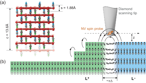
In this work, we use nanoscale scanning diamond magnetometry (NSDM) to investigate the spin structure of the pure intrinsic antiferromagnet Cr2O3. NSDM microscopy is an emerging quantum technique for the imaging of weak magnetic fields with nanometer spatial resolution (Fig. 2), with remarkable progress on antiferromagnets [28, 29, 4], multiferroics [30], and helimagnets [31]. Here, we extend NSDM to the imaging of antiferromagnetic domain-wall structures. We obtain quantitative information about the domain-wall width, chirality and surface magnetization, and connect it to a model of interplaying demagnetizing and anisotropy energies. We find that both Bloch and Néel walls can be present. Our work extends the knowledge about antiferromagnetic domain wall structure to the most basic class of intrinsic, bulk antiferromagnets.
II One-dimensional model of antiferromagnetic domain walls
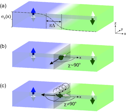
In order to motivate and explain our experimental observations, we briefly review the conventional model for static one-dimensional domain walls [23, 24] and extend it to collinear antiferromagnets. We consider a domain wall, as it occurs in, for example, Cr2O3, -Fe2O3, or CuMnAs. The domain wall separates two regions with magnetic order parameter pointing up () and down (), as shown schematically in Fig. 1. The key parameters of such a domain wall are the wall width and the twist angle between the wall magnetization and the -axis. Using this notation, Bloch walls correspond to and Néel walls to () for walls with right (left) chirality. and are determined by the interplay between exchange and anisotropy energies, and further modified by the demagnetizing field and DMI, if present. Considering only the first two contributions, the local domain wall energy density in the continuum limit reads:
| (1) |
where is the exchange stiffness, is the uniaxial anisotropy constant, and are the polar coordinates of the order parameter defined relative to the -axis shown in Fig. 1.
The static equilibrium solution that minimizes the total wall energy and satisfies the boundary conditions is given by:
| (2a) | ||||
| (2b) | ||||
where is the domain wall width [23, 25, 26]. The Cartesian coordinates of the order parameter can be easily derived from Eq. (2). For a layered antiferromagnet like Cr2O3, it is convenient to express and in terms of the intrinsic surface magnetization :
| (3a) | ||||
| (3b) | ||||
| (3c) | ||||
where we assume a domain wall centered at . The profile of is shown by a dash-dotted curve in Fig. 1(a). The total energy per unit area of the wall is given by .
We stress that, up to this point, the twist angle is arbitrary and independent of . In other words, for an antiferromagnetic system governed solely by exchange and anisotropy energies, Néel and Bloch domain walls (or any combination of the two) are degenerate in energy.
To understand the preference for one type of wall over the other, we next consider the effects of a demagnetizing field and of an in-plane magnetic anisotropy energy density . We note that, although the volume magnetization in an antiferromagnet is zero, a finite demagnetizing field still persists when due to the net magnetic moment of the domain wall [25, 32]. Keeping in mind these additional contributions, the domain wall energy per unit area changes to [23]:
| (4) |
where the in-plane easy axis is defined by the angle relative to the -axis. According to Eq. (4), the residual demagnetizing field favors the formation of Bloch walls over Néel walls (Fig. 1(b)). On the other hand, the in-plane anisotropy forces the magnetic moments to cant along the in-plane easy axis, leading to a competition between demagnetizing and anisotropy energies. For a sufficiently large in-plane anisotropy favoring the -direction (), we thus expect a Néel-type or a mixed Néel/Bloch-type domain wall (Fig. 1(c)).
The presence of a residual demagnetizing field and of in-plane anisotropy also leads to a modification of the domain wall width:
| (5) |
In particular, Eq. (5) predicts that the width of a Néel wall is reduced with respect to a Bloch wall, with a ratio given by:
| (6) |
where is approximately given by the magnetization of the polarized surface layer.
In addition to these interactions, the DMI can further lead to a preference for Néel-type domain walls when the Dzyaloshinskii vector runs parallel to the domain wall direction (the -axis, Fig. 1) [23, 24, 33]. Although the DMI is zero in bulk monodomain Cr2O3 for symmetry reasons [34], the formation of two magnetic domains with order parameter along breaks the inversion symmetry between two adjacent spins along . Such a symmetry breaking might allow for a finite DMI or higher-order chiral interactions to emerge in proximity of domain walls in Cr2O3[35]. If such local chiral interactions are larger or comparable to the demagnetizing energy, the domain walls will be of either Néel or intermediate Bloch-Néel-type with a unique chirality. The results presented in our study provide experimental support to this hypothesis.
III Materials and Methods
We investigate the domain wall structure and chirality in the prototypical 180∘ antiferromagnet Cr2O3. Cr2O3 is an antiferromagnetic insulator consisting of a hexagonal close packed array of O2- anions with of the octahedral holes occupied by Cr3+ [36] (Fig. 2a). Below , Cr2O3 forms an antiferromagnetically ordered phase, where the Cr3+ ions organize in alternating layers of opposite magnetic polarization (green and blue spins in Fig. 2a). Because of its fundamental role in antiferromagnetism, Cr2O3 has served as a model system for uniaxial antiferromagnetic order [34, 37, 38], magnetoelectric coupling [39, 40, 41], and electrically controlled exchange bias [42, 43]. More recently, Cr2O3 has attracted attention as a candidate material for antiferromagnetic magnetoelectric random access memories [28], spin colossal magnetoresistance [44], and as generator of sub-THz spin currents [45]. Although the domain wall plays a critical role in many of these phenomena, the spin structure is unknown beyond initial theoretical work [46], presenting an important experimental test case.
We investigate the Cr2O3 domain texture of three bulk single crystals. Samples A and B are grown by the Verneuil method and polished to a surface roughness of . Sample C is a flux-grown platelet with an as-grown surface. In a previous study [47], we found that the spin flop transition – normally requiring a magnetic field of (Ref. 36) – occurs spontaneously at in sample C, pointing to an unusually strong in-plane anisotropy. In addition, this sample has a lower Néel temperature (), probably due to strain or oxygen deficiency. We create antiferromagnetic domains by repeatedly cooling samples through the transition temperature using magnetoelectric poling [48] or until a multi-domain state spontaneously forms. Further details about the samples are given in Ref. 49.
We use a combination of optical second-harmonic generation (SHG) microscopy and NSDM to locate the antiferromagnetic domains and measure the domain wall profile. SHG is a non-linear optical method capable of resolving the global 180∘ domain pattern, yet has a diffraction-limited spatial resolution and is not sensitive to the absolute sign of the order parameter [50, 49]. To map the stray field distribution, we scan a diamond tip with a nitrogen vacancy (NV) center (orange arrow) at constant height () above the sample surface (Fig. 2b). The NV spin detects the component of the stray magnetic field parallel to its internal anisotropy axis (here off the surface normal [49]). The experiments are performed under ambient conditions at a temperature of 295 K.
IV Experimental Results
IV.1 Domain states
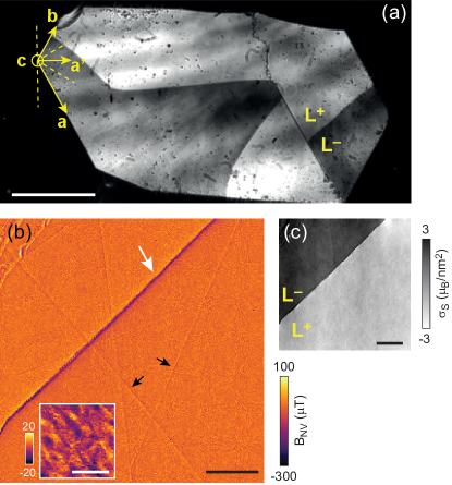
Figure 3(a) shows a laser-optical second-harmonic-generation (SHG) [47] micrograph of the global domain pattern. We observe that the domains in the bulk Cr2O3 crystals are large, typically in the range of hundreds of micrometers, and stable below , in agreement with earlier studies [50]. We find no correlation between the domain pattern and the in-plane crystal axes (Fig. 3a), indicating that the domain-wall location is set by the local defect or strain distribution or is completely random.
Once the domains are localized, we acquire high-resolution magnetic imaging scans along the domain walls using NSDM microscopy (Fig. 3b). The domain wall appears as a narrow track of strong magnetic stray field in the magnetometry image; this strong field is due to the reversal of uncompensated moments near the sample surface (see Fig. 2b). Fainter features within the domains reflect residual stray fields associated with surface topography [51]. We do not observe any correlation between the domain wall location and the sample structure, suggesting that there are no surface-induced pinning effects. Further, when cycling the sample through the transition temperature , domain walls usually form in random locations of the sample with no correlation between consecutive warming-cooling cycles.
To retrieve the absolute sign of the order parameter we reconstruct [49] the two-dimensional surface magnetization from the stray field map of Fig. 3b, shown in panel c. Here, a positive sign of (dark contrast) reflects a positive Cr3+ surface magnetization and order parameter (vice versa for ). We find that the correlation between SHG contrast and surface magnetization is maintained for all domain walls on all samples (Figs. S1 and S2 in Ref. 49). Combined with the absence of strong magnetic features in the interior of domains, these findings directly confirm that the magnetic polarization of Cr2O3 is robust against surface roughness [43, 29], and that Cr2O3 always terminates with the same Cr3+ surface magnetization for a given sign of the order parameter .
IV.2 Domain-wall cross-section
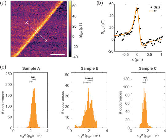
To investigate the internal structure of a domain wall, we acquire a large number of magnetometry images along the domain wall and analyze the magnitude and spatial profile of the stray field [52, 53]. We then compare the magnetic field along the cross section with the expected stray field from the static solution of the one-dimensional domain-wall model, Eq. (3), and compute the magnetic stray field from Eq. (3) using forward propagation[49]. By fitting the computed stray field to the experimental cross-section, we obtain quantitative estimates for the surface magnetization , domain-wall width , and twist angle . Figure 4(a,b) shows an exemplary line scan across a domain wall of sample C together with the least-squares fit. To build statistics and avoid possible cross-correlation between fit parameters, we analyze about line scans for each sample and validate results by a secondary data analysis (Figs. S3 and S4 in Ref. 49). To exclude long-term drifts, we acquire scans along a domain wall in random order and find no temporal correlations as we proceed with the scanning.
IV.3 Surface magnetization
Figure 4c reports quantitative measurements of the surface magnetization . We find a narrow distribution of values ranging from in sample C to in sample A. These values are only of the the theoretical for a perfectly ordered Cr3+ crystal, which is for the surface termination shown in Fig. 3(a) at zero temperature [49]. The low is partially explained by the decay of magnetic order close to , and is more pronounced for sample C due to the lower . According to Ref. 29, the surface magnetization close to is approximately given by , which gives at . Since low values for have also been reported by other experimental studies [54, 29], and since we observe a narrow distribution of that is uniform across the sample surface, we believe that the reduced is a general and unexplained property of Cr2O3. We hypothesize that the reduced surface moment density may be due to disorder within the exposed layer of terminating Cr3+ ions (see Fig. 2(a)).
IV.4 Domain wall chirality and width
Figure 5a-c plots the fit results for the domain-wall width and angle obtained from the extensive datasets recorded on samples A-C. Each plotted pair represents a magnetometry scan, and color-coding reflects the propagation direction of the domain wall. For samples A and B we find all domain walls to be predominantly Bloch-like, indicated by a angle close to (Fig. 5a,b). The domain-wall widths are not identical, but of similar magnitude , and well in the range of predicted by theory [46]. Clearly, there is no correlation between and the spatial location or propagation direction of the domain wall (see panels d,e), indicating that the crystal structure plays no role in domain-wall formation. The consistency of the results from the two samples, which are grown independently by the same technique, confirms that our methods for quantifying the domain-wall structure are robust and reproducible.
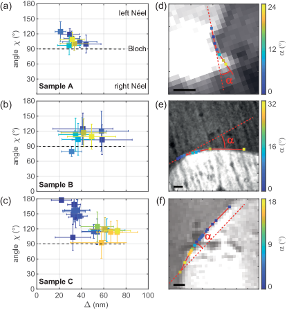
Interestingly, sample C – which has an unusually strong in-plane anisotropy [47] – shows a behavior that is distinctly different from samples A and B. Most prominently, we find both Néel and Bloch walls and a pronounced dependence of the twist angle on the wall orientation. For walls that run approximately parallel to one of magnetic hard axes (dashed lines in Fig. 3a and Fig. 5d-f), the domain wall has a distinct left Néel character (blue data points in Fig. 5c). Once the angle between the propagation direction and the hard axis exceeds about , the wall changes to Bloch-type, and becomes similar to samples A and B. In addition, the domain-wall width increases from in the Néel to in the Bloch configuration. The correlation between and is not complete, but pervasive, suggesting that a delicate balance of interactions determines the local structure of the wall.
V Discussion
The formation of distinct Bloch and Néel walls in Cr2O3 is intriguing, because in the absence of a demagnetizing field and in-plane anisotropy, the domain-wall energy of a collinear antiferromagnet is independent of the angle [23, 25, 26, 49]. Therefore, no domain-wall type is energetically favored. In Cr2O3, however, domain walls have a non-vanishing local magnetic moment associated with the spatially inhomogeneous order parameter [25, 32], giving rise to a small but non-zero demagnetizing field. We propose that this residual demagnetizing field, which is mostly a bulk effect, is responsible for the observation of Bloch walls in samples A and B, similar to the situation encountered in uniaxial ferromagnets [16].
The preference for Bloch walls is challenged once significant in-plane anisotropy is present (sample C). An in-plane anisotropy favors Cr3+ spins aligned with the in-plane easy axis and for a sufficiently strong anisotropy, the domain wall is expected to change from Bloch to Néel (see Section II). Due to the three-fold crystal symmetry of Cr2O3, three in-plane easy axes exist (that coincide with the crystal axes , and , see Fig. 3a) leading to six preferred directions in intervals. Therefore, the Cr3+ spins will tend to align to the nearest preferred easy direction. The alignment is strongest when the domain wall is perpendicular to an easy axis, explaining the appearance of Néel walls near (blue data points in Fig. 5c). Once becomes larger, the in-plane anisotropy torque is reduced, and the domain wall eventually changes back to a Bloch type (yellow data points). The critical angle where this change occurs is not well defined, but is roughly . At the same time as the domain-wall type changes from Néel to Bloch, the domain-wall width is expected to increase, in line with our observation (Fig. 5c). Using Eq. (6) and setting , the one-dimensional model predicts a ratio of domain-wall widths of for Cr2O3, in reasonable agreement with the experimental result of (Fig. 5c). The good overall agreement between experiment and theory motivates the conclusion that the non-vanishing magnetic moment and in-plane anisotropy determine the domain-wall structure of Cr2O3.
A final point that remains to be explained is the preference for left chiral Néel walls in sample C, which is also partially present in samples A and B (Fig. 5a-c). Although the asymmetry is conspicuous, it is not entirely surprising given the complex magnetoelectric properties of Cr2O3 [48]. Because the orientation of the spins in a left chiral Néel wall is against the stray field produced by the uncompensated magnetization of the top-most surface layers of Cr2O3 (Fig. 2b), the preference for left walls cannot be attributed to a magnetostatic effect, unlike the change of a Bloch wall into a Néel wall observed in the near-surface region of ferromagnets [16]. Future theoretical work shall determine whether a wall-related DMI or higher-order multispin interactions are responsible for the domain-wall chirality (see Section II). In a non-centrosymmetric environment, the DMI results in canting of the spins when has a non-zero in-plane component [34, 55], which – unlike in bulk Cr2O3 – may be the case within the Cr2O3 domain wall.
VI Summary and Outlook
In summary, we have resolved the spin structure of domain walls in the prototype uniaxial antiferromagnet Cr2O3. We propose that the structure of the domain wall is determined by the weak energy scales provided by the non-vanishing magnetization of the wall, the in-plane magnetic anisotropy, and possibly the DMI. Domain walls are Bloch-like in crystals with weak or negligible in-plane magnetic anisotropy, and either Bloch- or Néel-like in the crystal with larger in-plane anisotropy. In the latter case, the domain-wall type turns to Néel if the wall runs orthogonal to an in-plane easy axis, which coincides with the spin direction in the spin-flop phase of Cr2O3 [36]. In agreement with simple theoretical considerations, the domain-wall width decreases from in the Bloch configuration to in the Néel configuration. Finally, the comparison between SHG and NSDM allows for determining the absolute sign of the order parameter in different domains, which is not possible by optical imaging alone.
Besides its fundamental interest, insight into the domain walls of collinear antiferromagnets is relevant for the development of antiferromagnetic spintronic devices that exploit current-induced domain wall motion to switch the orientation of the order parameter [7, 6]. For example, in antiferromagnetic/heavy-metal bilayers the domain wall velocity is predicted to be zero for Bloch walls when considering only the damping-like spin-orbit torque, and nonzero but offset by a threshold current density when including the field-like spin-orbit torque [7]. In contrast, a nonzero domain-wall velocity is predicted for Néel walls at any current density (in the absence of pinning), making this type of wall much more efficient for achieving current-induced domain-wall displacements. In our work, we show that the residual demagnetization field in the walls of a collinear antiferromagnet with unixial anisotropy favors the formation of Bloch walls, whereas the presence of in-plane magnetocrystalline anisotropy, likely in combination with chiral spin interactions, favors the formation of Néel walls. Future studies should aim at confirming the presence of a wall-related bulk DMI in Cr2O3 and determine whether an additional interfacial DMI can be induced by proximity to a heavy metals like Pt.
Acknowledgements.
We acknowledge T. Weber for support with the X-ray platform at the Materials Department of ETH Zurich, and N. Spaldin for insightful discussions. This work was supported by ETH Zurich and the Swiss Competence Centre for Materials Science and Technology (CCMX). C.D. acknowledges support by the Swiss National Science Foundation (SNFS) under grant no. 200020_175600, by the SNFS under the NCCR QSIT, and by the European Commission under grant no. 820394 “ASTERIQS”. P.G. acknowledges support by the SNFS under grant no. 200020_172775. M.F. acknowledges support by the SNSF under grant no. 200021_178825 and FAST, a division of the NCCR MUST ETH FAST 3 via PSP 1-003448-054.References
- Shpyrko et al. [2007] O. Shpyrko, E. Isaacs, J. Logan, Y. Feng, G. Aeppli, R. Jaramillo, H. Kim, T. Rosenbaum, P. Zschack, M. Sprung, et al., Direct measurement of antiferromagnetic domain fluctuations, Nature 447, 68 (2007).
- Radu and Zabel [2008] F. Radu and H. Zabel, Exchange bias effect of ferro-/antiferromagnetic heterostructures, in Magnetic heterostructures (Springer, 2008) pp. 97–184.
- Jaramillo et al. [2007] R. Jaramillo, T. F. Rosenbaum, E. D. Isaacs, O. G. Shpyrko, P. G. Evans, G. Aeppli, and Z. Cai, Microscopic and macroscopic signatures of antiferromagnetic domain walls, Phys. Rev. Lett. 98, 117206 (2007).
- Wörnle et al. [2019] M. Wörnle, P. Welter, Z. Kašpar, K. Olejník, V. Novák, R. Campion, P. Wadley, T. Jungwirth, C. Degen, and P. Gambardella, Current-induced fragmentation of antiferromagnetic domains, arXiv:1912.05287 (2019).
- Hals et al. [2011] K. M. D. Hals, Y. Tserkovnyak, and A. Brataas, Phenomenology of current-induced dynamics in antiferromagnets, Phys. Rev. Lett. 106, 107206 (2011).
- Gomonay et al. [2016] O. Gomonay, T. Jungwirth, and J. Sinova, High antiferromagnetic domain wall velocity induced by Néel spin-orbit torques, Phys. Rev. Lett. 117, 017202 (2016).
- Shiino et al. [2016] T. Shiino, S.-H. Oh, P. M. Haney, S.-W. Lee, G. Go, B.-G. Park, and K.-J. Lee, Antiferromagnetic domain wall motion driven by spin-orbit torques, Physical review letters 117, 087203 (2016).
- Baldrati et al. [2019] L. Baldrati, O. Gomonay, A. Ross, M. Filianina, R. Lebrun, R. Ramos, C. Leveille, F. Fuhrmann, T. R. Forrest, F. Maccherozzi, S. Valencia, F. Kronast, E. Saitoh, J. Sinova, and M. Kläui, Mechanism of Néel order switching in antiferromagnetic thin films revealed by magnetotransport and direct imaging, Phys. Rev. Lett. 123, 177201 (2019).
- Jungwirth et al. [2016] T. Jungwirth, X. Marti, P. Wadley, and J. Wunderlich, Antiferromagnetic spintronics, Nature Nanotechnology 11, 231 (2016).
- Baltz et al. [2018] V. Baltz, A. Manchon, M. Tsoi, T. Moriyama, T. Ono, and Y. Tserkovnyak, Antiferromagnetic spintronics, Rev. Mod. Phys. 90, 015005 (2018).
- Manchon et al. [2019] A. Manchon, J. Železný, I. M. Miron, T. Jungwirth, J. Sinova, A. Thiaville, K. Garello, and P. Gambardella, Current-induced spin-orbit torques in ferromagnetic and antiferromagnetic systems, Rev. Mod. Phys. 91, 035004 (2019).
- Duine et al. [2018] R. A. Duine, K. J. Lee, S. S. P. Parkin, and M. D. Stiles, Synthetic antiferromagnetic spintronics, Nature Physics 14, 10.1038/s41567-018-0050-y (2018).
- Yang et al. [2015] S.-H. Yang, K.-S. Ryu, and S. Parkin, Domain-wall velocities of up to 750 m/s driven by exchange-coupling torque in synthetic antiferromagnets, Nature Nanotechnology 10, 10.1038/nnano.2014.324 (2015).
- Luo et al. [2019] Z. Luo, T. P. Dao, A. Hrabec, J. Vijayakumar, A. Kleibert, M. Baumgartner, E. Kirk, J. Cui, T. Savchenko, G. Krishnaswamy, L. J. Heyderman, and P. Gambardella, Chirally coupled nanomagnets, Science 363, 1435 (2019).
- Hrabec et al. [2020] A. Hrabec, Z. Luo, L. J. Heyderman, and P. Gambardella, Synthetic chiral magnets promoted by the dzyaloshinskii–moriya interaction, Applied Physics Letters 117, 130503 (2020).
- Hubert and Schäfer [2008] A. Hubert and R. Schäfer, Magnetic Domains: The Analysis of Magnetic Microstructures (Springer Berlin Heidelberg, 2008).
- Geng et al. [2014] Y. Geng, H. Das, A. L. Wysocki, X. Wang, S. W. Cheong, M. Mostovoy, C. J. Fennie, and W. Wu, Direct visualization of magnetoelectric domains, Nature Materials 13, 163 (2014).
- Cheong et al. [2020] S. W. Cheong, M. Fiebig, W. Wu, L. Chapon, and V. Kiryukhin, Seeing is believing: visualization of antiferromagnetic domains, npj Quantum Materials 5, 10.1038/s41535-019-0204-x (2020).
- Hellwig et al. [2003] O. Hellwig, A. Berger, and E. E. Fullerton, Domain walls in antiferromagnetically coupled multilayer films, Phys. Rev. Lett. 91, 197203 (2003).
- Weber et al. [2003] N. Weber, H. Ohldag, H. Gomonaj, and F. Hillebrecht, Magnetostrictive domain walls in antiferromagnetic NiO, Physical review letters 91, 237205 (2003).
- Ravlić et al. [2003] R. Ravlić, M. Bode, A. Kubetzka, and R. Wiesendanger, Correlation of dislocation and domain structure of Cr(001) investigated by spin-polarized scanning tunneling microscopy, Physical Review B 67, 174411 (2003).
- Bode et al. [2006] M. Bode, E. Vedmedenko, K. Von Bergmann, A. Kubetzka, P. Ferriani, S. Heinze, and R. Wiesendanger, Atomic spin structure of antiferromagnetic domain walls, Nature materials 5, 477 (2006).
- Malozemoff and Slonczewski [2016] A. Malozemoff and J. Slonczewski, Magnetic Domain Walls in Bubble Materials: Advances in Materials and Device Research, Vol. 1 (Academic press, 2016).
- Gyorgy and Hagedorn [1968] E. M. Gyorgy and F. B. Hagedorn, Analysis of domain‐wall motion in canted antiferromagnets, Journal of Applied Physics 39, 88 (1968), https://doi.org/10.1063/1.1655786 .
- Papanicolaou [1995] N. Papanicolaou, Antiferromagnetic domain walls, Physical Review B 51, 15062 (1995).
- Mitsumata and Sakuma [2011] C. Mitsumata and A. Sakuma, Generalized model of antiferromagnetic domain wall, IEEE transactions on magnetics 47, 3501 (2011).
- Chen et al. [2019] Z. Chen, Z. Yan, M. Qin, and J.-M. Liu, Landau-Lifshitz-Bloch equation for domain wall motion in antiferromagnets, Physical Review B 99, 214436 (2019).
- Kosub et al. [2017] T. Kosub, M. Kopte, R. Hühne, P. Appel, B. Shields, P. Maletinsky, R. Hübner, M. O. Liedke, J. Fassbender, and O. G. Schmidt, Purely antiferromagnetic magnetoelectric random access memory, Nature Communications 8, 1 (2017).
- Appel et al. [2019] P. Appel, B. J. Shields, T. Kosub, N. Hedrich, R. Hubner, J. Fassbender, D. Makarov, and P. Maletinsky, Nanomagnetism of magnetoelectric granular thin-film antiferromagnets, Nano Letters 19, 1682 (2019).
- Gross et al. [2017] I. Gross, W. Akhtar, V. Garcia, L. Martínez, S. Chouaieb, K. Garcia, C. Carrétéro, A. Barthélémy, P. Appel, P. Maletinsky, et al., Real-space imaging of non-collinear antiferromagnetic order with a single-spin magnetometer, Nature 549, 252 (2017).
- Dussaux et al. [2016] A. Dussaux, P. Schoenherr, K. Koumpouras, J. Chico, K. Chang, L. Lorenzelli, N. Kanazawa, Y. Tokura, M. Garst, A. Bergman, C. L. Degen, and D. Meier, Local dynamics of topological magnetic defects in the itinerant helimagnet FeGe, Nature Communications 7, 12430 (2016).
- Tveten et al. [2016] E. G. Tveten, T. Müller, J. Linder, and A. Brataas, Intrinsic magnetization of antiferromagnetic textures, Physical Review B 93, 104408 (2016).
- Heide et al. [2008] M. Heide, G. Bihlmayer, and S. Blügel, Dzyaloshinskii-moriya interaction accounting for the orientation of magnetic domains in ultrathin films: Fe/w (110), Physical Review B 78, 140403 (2008).
- Dzyaloshinsky [1958] I. Dzyaloshinsky, A thermodynamic theory of “weak” ferromagnetism of antiferromagnetics, Journal of Physics and Chemistry of Solids 4, 241 (1958).
- Moriya [1960] T. Moriya, Anisotropic superexchange interaction and weak ferromagnetism, Phys. Rev. 120, 91 (1960).
- Fiebig et al. [1996] M. Fiebig, D. Fröhlich, and H. J. Thiele, Determination of spin direction in the spin-flop phase of , Phys. Rev. B 54, R12681 (1996).
- Rado and Folen [1962] G. T. Rado and V. J. Folen, Magnetoelectric effects in antiferromagnetics, in Proceedings of the Seventh Conference on Magnetism and Magnetic Materials, edited by J. A. Osborn (Springer US, Boston, MA, 1962) pp. 1126–1132.
- Brockhouse [1953] B. N. Brockhouse, Antiferromagnetic structure in , The Journal of Chemical Physics 21, 961 (1953).
- Astrov [1961] D. Astrov, Magnetoelectric effect in chromium oxide, Sov. Phys. JETP 13, 729 (1961).
- Martin and Anderson [1966] T. Martin and J. Anderson, Antiferromagnetic domain switching in , IEEE Transactions on Magnetics 2, 446 (1966).
- Mostovoy et al. [2010] M. Mostovoy, A. Scaramucci, N. A. Spaldin, and K. T. Delaney, Temperature-dependent magnetoelectric effect from first principles, Phys. Rev. Lett. 105, 087202 (2010).
- Borisov et al. [2005] P. Borisov, A. Hochstrat, X. Chen, W. Kleemann, and C. Binek, Magnetoelectric switching of exchange bias, Physical Review Letters 94, 117203 (2005).
- He et al. [2010] X. He, Y. Wang, N. Wu, A. N. Caruso, E. Vescovo, K. D. Belashchenko, P. A. Dowben, and C. Binek, Robust isothermal electric control of exchange bias at room temperature, Nature Materials 9, 579 (2010).
- Qiu et al. [2018] Z. Qiu, D. Hou, J. Barker, K. Yamamoto, O. Gomonay, and E. Saitoh, Spin colossal magnetoresistance in an antiferromagnetic insulator, Nature materials 17, 577 (2018).
- Li et al. [2020] J. Li, C. B. Wilson, R. Cheng, M. Lohmann, M. Kavand, W. Yuan, M. Aldosary, N. Agladze, P. Wei, M. S. Sherwin, et al., Spin current from sub-terahertz-generated antiferromagnetic magnons, Nature 578, 70 (2020).
- Kota and Imamura [2016] Y. Kota and H. Imamura, Narrowing of antiferromagnetic domain wall in corundum-type by lattice strain, Applied Physics Express 10, 013002 (2016).
- Pisarev et al. [1997] R. V. Pisarev, M. Fiebig, and D. Fröhlich, Nonlinear optical spectroscopy of magnetoelectric and piezomagnetic crystals, Ferroelectrics 204, 1 (1997).
- Krichevtsov et al. [1988] B. B. Krichevtsov, V. V. Pavlov, and R. V. Pisarev, Nonreciprocal optical effects in antiferromagnetic subjected to electric and magnetic fields, Sov. Phys. JETP 67, 378 (1988).
- [49] See Supplemental Material accompanying this manuscript .
- Fiebig et al. [1995] M. Fiebig, D. Fröhlich, G. Sluyterman v. L., and R. V. Pisarev, Domain topography of antiferromagnetic by second-harmonic generation, Applied Physics Letters 66, 2906 (1995).
- [51] N. Hedrich, K. Wagner, O. V. Pylypovskyi, B. J. Shields, T. Kosub, D. D. Sheka, D. Makarov, and P. Maletinsky, Nanoscale mechanics of antiferromagnetic domain walls, submitted .
- Tétienne et al. [2015] J. P. Tétienne, T. Hingant, L. J. Martinez, S. Rohart, A. Thiaville, L. H. Diez, K. Garcia, J. P. Adam, J. V. Kim, J. F. Roch, I. M. Miron, G. Gaudin, L. Vila, B. Ocker, D. Ravelosona, and V. Jacques, The nature of domain walls in ultrathin ferromagnets revealed by scanning nanomagnetometry, Nat. Commun. 6, 6733 (2015).
- Vélez et al. [2019] S. Vélez, J. Schaab, M. S. Wörnle, M. Müller, E. Gradauskaite, P. Welter, C. Gutgsell, C. Nistor, C. L. Degen, M. Trassin, M. Fiebig, and P. Gambardella, High-speed domain wall racetracks in a magnetic insulator, Nature Communications 10, 4750 (2019).
- Astrov et al. [1996] D. N. Astrov, N. B. Ermakov, A. S. Borovik-Romanov, E. G. Kolevatov, and V. I. Nizhankovskii, External quadrupole magnetic field of antiferromagnetic , Journal of Experimental and Theoretical Physics Letters 63, 745 (1996).
- Mu and Belashchenko [2019] S. Mu and K. D. Belashchenko, Influence of strain and chemical substitution on the magnetic anisotropy of antiferromagnetic : An ab-initio study, Phys. Rev. Materials 3, 034405 (2019).