Near-field simulations of pellet ablation for disruptions mitigation in tokamaks
Abstract
Detailed numerical studies of the ablation of a single neon pellet in the plasma disruption mitigation parameter space have been performed. Simulations were carried out using FronTier, a hydrodynamic and low magnetic Reynolds number MHD code with explicit tracking of material interfaces. FronTier’s physics models resolve the pellet surface ablation and the formation of a dense, cold cloud of ablated material, the deposition of energy from hot plasma electrons passing through the ablation cloud, expansion of the ablation cloud along magnetic field lines and the radiation losses. A local thermodynamic equilibrium model based on Saha equations has been used to resolve atomic processes in the cloud and Redlich-Kwong corrections to the ideal gas equation of state for cold and dense gases have been used near the pellet surface. The FronTier pellet code is the next generation of the code described in [R. Samulyak, T. Lu, P. Parks, Nuclear Fusion, (47) 2007, 103–118]. It has been validated against the semi-analytic improved Neutral Gas Shielding model in the 1D spherically symmetric approximation. Main results include quantification of the influence of atomic processes and Redlich-Kwong corrections on the pellet ablation in spherically symmetric approximation and verification of analytic scaling laws in a broad range of pellet and plasma parameters. Using axially symmetric MHD simulations, properties of ablation channels and the reduction of pellet ablation rates in magnetic fields of increasing strength have been studied. While the main emphasis has been given to neon pellets for the plasma disruption mitigation, selected results on deuterium fueling pellets have also been presented.
I Introduction
Effective and reliable disruption mitigation is critical for the International Thermonuclear Experimental Reactor (ITER) and future burning plasma devices. The most likely candidate for the ITER plasma disruption mitigation system (DMS) is the Shatterd Pellet Injection (SPI). In SPI, a large pellet, composed of a frozen mixture of neon and deuterium, is injected inside a breaker tube causing fragmentation. The plume of pellet fragment ablates in the plasma, radiates, and induces a thermal quench. A prototype DMS using SPI, tested on DIII-D, has been largely successful Commaux16 ; Shiraki16 ; Shiraki_Commaux16 and it is now critical to develop methods to extrapolate those results to the much higher temperatures and magnetic fields of ITER.
The ablation of cryogenic pellets and SPI fragments in tokamaks is an intrinsic multiscale and multiphysics phenomenon. The spatial scales of the problem range from sub-millimeter-size (the scale of high density gradients in the ablation cloud near the pellet surface, affecting the ablation rates) to multi-meter-size (the distances traveled by the ablated material in tokamak plasma). Tokamak codes such as M3D-C1 and NIMROD have performed simulations of the tokamak plasma dynamics in the presence of ablating impurities (jets), pellets and SPI fragments Izzo06 ; Kim19 ; Lyons19 . Such global scale numerical simulations cannot resolve physics processes determining pellet ablation rates and employ semi-analytic models for impurities. In contract, pellet ablation models that resolve all relevant physics processes occurring on the pellet surface and in the ablation cloud and compute pellet ablation rates, constrain themselves to domains of the order of 10 - 50 cm around the pellet, and use tokamak plasma parameters as input. Borrowing the terminology adopted in electromagnetism, we call such models near-field pellet models.
Near-field pellet ablation models have been explored in the past in theoretical and simulation works. Previous and on going analytical and semi-analytical studies developed an elegant and robust theory of the mechanisms of single pellet ablation Parks_transonic ; Kuteev_1995 ; Parks_Ishizaki04 and when supplemented with additional physics ( force) provide valuable insight for penetration studies Samulyak07 . See Pegourie_2007 and references therein for the summary and other details.
During the pellet ablation, hot plasma electrons impact on the pellet surface causing a rapid ablation and the fiormaiton of a dense, cold cloud of neutral atoms expanding isotropically. This cloud partially shields the pellet from the incoming plasma energy flux and is the main factor controlling the ablation rate. The pellet material heats up, undergoes atomic processes (multiple ionization / recombination for neon and dissociation and ionization for deuterium pellets), and expands along magnetic fields lines by forces. From Parks_1992 ; Samulyak07 the magnetic Reynold’s number , where is the length scale, is the field transverse velocity and is the ablation cloud transverse conductivity in the vicinity of the pellet, moreover the magnetic in the far field, under these circumstances the magnetic field is taken to be constant and externally given, supporting the electrostatic MHD approximation. The process of grad-B drift of the ablated material across magnetic field lines Rozhanskij_1994 ; Parks_2005 establishes a finite length of the cloud providing shielding to the pellet (the shielding length).
In our work, numerical methods and algorithms for the near-field pellet ablation model are implemented as magnetohydrodynamic extensions of the FronTier-Lite Fix06 project and can be considered as the next generation of the pellet ablation code described in Samulyak07 . FronTier-Lite provides an application programming interface (API) for front tracking Glimm1998ThreeDimensionalFT , a hybrid Lagrangian-Eulerian method in which a dynamically evolving interface (a Lagrangian mesh) is computed on a fixed volume-filling Eulerian mesh. Front tracking preserves and maintains sharp discontinuities by prohibiting taking derivatives across interfaces of steep gradients. The pellet surface separating the pellet interior from the surrounding ablated material and the interface between the ablated material and the ambient plasma are explicitly tracked in our model. Tracking of the interface between the ablated material and the ambient plasma is a significant improvement compared to the previous model Samulyak07 , in which only the pellet surface was explicitly resolved, as it greatly improves the distribution of hydrodynamic states across the ablation cloud and eliminates the numerical diffusion across the ablated cloud - background plasma interface. The use of high order hyperbolic WENO solvers is another improvement compared to Samulyak07 . Contrary to the MUSCL based scheme used in Samulyak07 WENO solver does not require solving an exact Riemann problem at each cell interface. This facilitates the implementation of more elaborate equation of states. The code is validated with comparison to the 1D theoretical predictions and scaling laws for an ideal neon cloud. The present work improves also several physics models of Samulyak07 such as the kinetic electron heating model and the EOS and adds new models such as radiation that was not applicable for hydrogen pellets.
Due to the axially-symmetric approximation, the grad-B drift of the ablated material across magnetic field lines Parks_Sessions_Baylor cannot be explicitly resolved. We instead impose a fixed shielding length of the ablation cloud obtained by theoretical estimates. This restriction will be removed in our forthcoming paper which will report full 3D simulations of the ablation of single pellets and SPI fragments using an adaptive Lagrangian particle code EPS-2018 developed as an extension of the Lagrangian particle hydrodynamic method LP .
The paper is organized as follows. In Sec.II introduces equations governing the evolution of the ablation cloud in the low magnetic Reynolds number MHD approximation as well as the equation of state electronic heat flux, conductivity and radiation models. In Sec.III, we describe in more details the numerical implementation of each component of the model. In Sec.IV we present verification of our model with semi-analytical results as well as MHD studies in a broad range of tokamak magnetic fields. While the main emphasis has been given to neon pellets in the plasma disruption regime, selected results on deuterium fueling pellets have also been presented. Finally, we conclude the paper in Sec.V with an overview of the present work and future studies using full 3D SPI numerical models.
II Model approximations and governing equations
II.1 Equations for compressible hydrodynamics with electromagnetic terms
Following Samulyak07 , we assume low magnetic Reynold’s number approximation for MHD processes in the ablated pellet cloud,
where is the current induced magnetic field. A detailed analysis of the field distortion near an ablating hydrogen pellet can be found in Parks_distorsion . Downstream from the pellet, the cloud pressure is such that and the external magnetic field is unperturbed by the ablation flow. The magnetic field is therefore assumed constant in time and uniform . The governing system of equation simplifies as follows
| (1a) | ||||
| (1b) | ||||
| (1c) | ||||
| (1d) | ||||
where , and are the velocity, density and specific internal energy of the fluid, respectively, is the pressure, is the current density and is the fluid conductivity. The electron heat flux is represented by an external heat source - described in detail in Section II.3. In the system eq.1 we neglect the effects of heat conduction and viscosity. Finally, the system is closed by an equation of state (EOS) (1d). Several EOS models will be discussed in Section II.2.
We ignore pellet motion effects, and carry out the simulations in the system of cylindrical coordinates (, , ). Since the coordinate is eliminated (), the flow is constrained to axial symmetry with respect to the -axis passing through the pellet center. The current density is obtained from the Ohm’s law
| (2) |
Assuming a uniform distribution of the electric potential due to the pellet charging () and the axial symmetry of the ablation flow along magnetic field lines, this equation reduces to
| (3) |
II.2 Equation of state
Details of transonic regimes of the ablation flow strongly depend on the equation of state used to close the system of equations (1). Most of our verification results in spherically symmetric approximation (IV.1.1) were obtained using the ideal gas EOS model. For more realistic MHD simulations, it is critical that the EOS be able to capture accurately atomic and other complex processes in the flow. In the next subsection, we briefly describe our model based on the Redlich-Kwong equation of state (RK EOS), which we use to probe deviations of gas states in the cold dense region near the pellet surface from the ideal gas state. The EOS model that resolves atomic processes will be discussed in II.2.2.
II.2.1 Redlich-Kwong equation of state
The region of the cloud closest to the pellet is formed of dense and cold ablated material. We implemented the Redlich-Kwong RK equation of state (RK EOS) to better capture this thin layer where the vapor might deviate from the ideal gas assumption. RK EOS improves the accuracy of the Van der Waals model by proposing a temperature dependence for the attractive term
| (4) |
where is the molar volume and
| (5a) | ||||
| (5b) | ||||
where K and bars.
We need to derive explicit expressions for all thermodynamic functions for the RK EOS as they are necessary for the numerical implementation of our EOS library. From the second law of thermodynamic,
| (6) |
we have,
| (7) |
Using the Maxwell relation,
| (8) |
and (4), we obtain,
| (9a) | ||||
| (9b) | ||||
| (9c) | ||||
Performing integration,
| (10) |
Applying the ideal EOS limit, we find the unknown function :
| (11) |
Therefore, the molar internal energy is
| (12) |
Substituting (8) and (9) into the second law of thermodynamics and performing integration, we find the expression for the entropy,
| (13) |
The Grüneisen gamma can be found by taking differential of the entropy equation:
| (14) | ||||
II.2.2 EOS resolving atomic processes
The fast electrons coming from the ambient plasma slow down in the ablated material cloud and deposit energy into the gas, causing ionization and heating. This chain of events is responsible for thermal ionization, which usually dominates fast electron impact ionization. The degree of ionization is very low in proximity to the surface of the pellet (mostly neutral atoms) and it becomes progressively higher further downstream as the temperature, and thus thermal ionization, steadily increases. The distribution of the multiply ionized states are found by solving a coupled set of Saha equations, which depends only on local values of the temperature and mass density. For high-Z pellets, multiple ionization levels introduce energy sinks that strongly influence the temperature and conductivity of the cloud.
Using the expression for specific internal energy from Zeldovich and neglecting electronic excitations, we obtain
| (15) |
where is the mass of an ion (atom), is the degree of ionization of the gas, and is the concentration of m-ions. and are subject to the conservation conditions,
where , , are the number density of respectively, all the nuclei, the ions and electrons. The pressure is given by,
| (16) |
The system of Saha equations relating particle concentrations is as follows
| (17) |
where is the Planck constant and (for ) are known electron partition functions. This system together with the conservation equations of mass and charge suffice to completely determine the particle concentrations and . Substituting parameters of neon, the Saha system becomes [cgs-eV units]
| (18) |
Since it is prohibitively expensive to solve the coupled Saha system of equations in a time-dependent hydrodynamic simulation, a tabular EOS was used. 2D arrays were constructed using independent variables (, ) and (, ) incremented evenly in space on a fine mesh over the range of interest for , , . The ionization fractions were obtained by solving (18) on these meshes and the pertinent thermodynamic quantities computed and saved. During runtime, we access these quantities using standard libraries for table look-up and cubic spline interpolation algorithms.
II.3 Electron heat flux model
The electron heat flux model is similar to the one described in Samulyak07 ; Parks_Ishizaki04 but has been updated for high-Z elements Parks_2020 where the normalized heat flux is given by,
| (19) |
where ”+” (”-”) refers to right (left) going plasma electrons, and is the corresponding heat deposition rate per unit volume. The 3-D linearized Fokker-Planck kinetic equation is solved for the electron distribution function where , , are the energy, velocity space variables and cosine pitch-angle with respect to the magnetic field, respectively. Although slowing down and pitch-angle scattering on a neutral target is weaker than it is on partially ionized target, there is not a great difference between scattering by a neutral atom with atomic number and the atom in a partially ionized state with ionic charge , provided that it is only weakly ionized, . The expression for depends weakly on the electron energy and is provided as tabulated data for neon and hydrogen species in the code. The numerical solution for parallel electron heat flux can be accurately fit to a Bessel function,
| (20a) | ||||
| (20b) | ||||
| (20c) | ||||
| (20d) | ||||
| (20e) | ||||
Here is the half-space incident Maxwellian heat flux, is the surface albedo (reflectivity) due to collisional backscattering, is the decrease due to electrostatic shielding, is the modified Bessel function of order and,
| (21a) | ||||
| (21b) | ||||
| (21c) | ||||
where , with and the total number density of nuclei and mass density respectively of the fluid and the mass of the atom. Here are the density integrals of the (bound) ablation electrons and is an effective energy flux attenuation thickness of the hot, streaming electrons due to slowing down and pitch-angle scattering.
The Bessel function form is the analytical solution when the pitch-angle scattering term is neglected (an explicit derivation of this claim is provided in the appendix of Parks_Ishizaki04 ), in which case,
| (22) |
is the Bethe stopping power logarithm pertaining to inelastic scattering of fast electrons of atomic (bound) electron in the neutral gas layer, where is the Napier constant, is the mean excitation energy for neutral atoms required for computing the energy loss of fast electrons passing through matter. The analysis is restricted to the standard Bethe regime , which corresponds to and the Coulomb logarithm is evaluated at since that is the average energy per particle transported into the cloud/pellet system from a distribution of semi-isotropic incident Maxwellian electrons. Using values recommended by ICRU , eV, , eV, , eV, . For partially ionized atoms, the corresponding I-values are larger and increase monotonically with ionic charge state. However, the dense, cold region near the pellet, which provides most of the shielding, is typically composed of a mix of neutral atoms and predominately singly charged ions, and the latter have only modestly () larger -values than neutral-atom ones Stopping_power . In the current work the small difference is discarded since atomic processes are of minor importance to the ablation rate. An analogous “Coulomb logarithm” arises from multiple small-angle elastic scattering collisions between fast electrons and the shielded atomic nucleus. For keV electrons, the use of the Thomas-Fermi atomic field model indicates that for all atomic number . For convenience, the model discounts the difference between the two Coulomb logarithms by using the same formula in both energy loss and elastic scattering processes.
Finally the heat source from the energy deposition by hot, long mean-free path electrons streaming into the ablation cloud along the magnetic field lines is given by,
| (23) |
and the heat deposition on the surface is given as,
| (24) |
II.4 Conductivity and radiation
The conductivity model for hydrogenic species has been derived in Samulyak07 . For high-Z impurities the conductivity model was derived in Parks_SCIDAC and we review it here. Observing that LTE conditions must prevail in the ablatant cloud, the Saha system of equations can be used to determine each partial ionization fraction and then the local average ionization level defined by,
| (25) |
where is the charge state of ion with density and () is the number density of free electrons (nuclei). Evaluating the conductivity for the ablation of high-Z impurities requires a slightly different average charge state sum,
| (26) |
where . Using the sum rule the conductivity is,
| (27) |
where is the electron-ion momentum exchange collision frequency and is the electron-neutral momentum exchange collision frequency. After evaluating and , the conductivity transverse to the magnetic field is given by [eV-cgs]
| (28) |
In the absence of neutrals, (28) reduces to the Spitzer transverse conductivity,
| (29) |
where is the charge state.
To account for radiation losses in the neon ablation clouds, we use a non-LTE radiation model in the thin optical limit approximation. The numerical algorithm uses tabulated emissivity table precomputed with the CRETIN code CRETIN .
II.5 Surface ablation model
One detail of our pellet model remains to be explored and it is that of the physics of the phase transition at the pellet surface. After injection in the reactor plasma, the pellet is subjected to a pre-heating period in the sub-microsecond range that ends when its outer layers reach values close to the sublimation energy ( eV, eV for neon and hydrogen respectively). From this moment forward the ablation phase begins. Atomic or molecular layers are continuously removed from the pellet providing the source of the expanding cloud. The authors of Parks_Turnbull_Foster give a qualitatively simple picture of the processes at the surface: by the time the energetic plasma electrons reach the surface of the pellet most of their energy has been degraded into thermal energy in the cloud, which drives the cloud expansion and outward flow. As a result they have an effective penetration range in the pellet of the order of the micrometer or less. A thin layer underneath the surface conducts the heat into the pellet and also back to the surface. The heat conducted into the pellet has been shown Parks_Turnbull_Foster to be negligible compared to that conducted to the surface. Because the energy required to vaporize the outer pellet layer is several orders of magnitude smaller compared to the first ionization potential, only a small fraction of the atoms leave the surface ionized (). Therefore, all the energy striking the pellet can be assumed to sustain the sublimation, this process does not raise the temperature of the pellet and the vapor layer around the pellet consists only of neutral atoms and/or molecules.
The system of differential equations 1 governing the ablation requires three boundary conditions at the pellet surface, which are determined by considering,
-
the transition from solid to vapor,
-
the energy balance across the solid/vapor transition layer,
-
the change in flow states along the backward characteristic originating from the Riemann problem at the pellet surface (the flow of vaporized material is subsonic) .
The discussion above justifies using constant temperature for vapor at the pellet surface. The dense and cold vapor near the surface is described by the Redlich-Kwong EOS discussed in Section II.2.1. We will show in Section IV.1.1 that the deviation from the ideal gas EOS causes negligibly small changes in the pellet ablation process. This we assume that the vapor temperature near the pellet surface is
| (30) |
which for a neon pellet is K and K for a deuterium pellet, as it assures the ideal gas behavior over a wide range of pressure ( bars) typical of the surface pressure .
The energy balance across the solid/gas transition layer is given by,
| (31) | ||||
| (32) |
where is the mass flux of the eroded pellet material with the surface recession speed. The second equality comes about because . is the temperature of the cryogenic solid pellet, is the temperature of the vaporized material to satisfy (30) and is the heat capacity of ideal gas at constant pressure ( for Ne and for D2, with J/K mol). The cohesive energy of solid is the latent heat of sublimation (1902 J/mol for Ne and 1243 J/mol for ), the energy that must be supplied to convert the atoms of the solid into well separated neutral atoms at rest. The last undefined term, is the specific heat at constant pressure of the solid pellet and used to compute the energy of formation of the cryogenic pellet,
| (33) |
Finally, to extract the last boundary condition we reuse a derivation proposed in Samulyak07 . Since the flow at the pellet is subsonic, the structure of the Riemann problem contains a backward characteristic connecting the vapor to the surface of the solid pellet. Furthermore, noting that the gas is mostly neutrals and very close to ideal at the surface we can write down the characteristic equation,
| (34) |
with the characteristic derivative,
| (35) |
and is the sound speed, is the Gruneisen coeffecient, N is the normal direction to the surface and is 0, 1, or 2 for rectangular, cylindrical or spherical geometry.These three boundary conditions are sufficient to accurately describe the phase transition process.
III Implementation
MHD processes in the pellet ablation cloud are approximated by the low magnetic Reynolds number MHD equations. The boundary between plasma and cloud can be approximated as sharp and is explicitly tracked during the simulation. The interface is represented as a co-dimension one Lagrangian mesh moving on an Eulerian mesh and we use a front tracking method for the dynamic motion and topological changes of that interface. Front tracking is implemented in our code using the FronTier-Lite API Fix06 ; glimm_axisymmetric ; 2007JCoPh.226.1532S which implements front tracking for inviscid flows and provide robust facilities for interfacing with the front geometry. In this framework, the front is represented (in 2D) by a piecewise linear curve moving according to the contact discontinuity that it represents while the flow fields are solved on the fixed-in-time spatial grid (Eulerian) representing the bulk fluid.
Tracking the cloud/plasma interface explicitly keeps the boundary between the two media sharp and removes interfacial numerical diffusion by forbidding taking finite differences across thin, steep gradient regions. Following Parks_AC , we neglect the weak diamagnetic current layer at the cloud boundary and associated jump in magnetic field pressure, leading us to formulate a contact discontinuity boundary condition at the interface,
| (36) |
The ablated material is supported by the background plasma . One of the benefits to adopting front tracking for the cloud boundary is that it enables us to solve the governing equations only in the region of interest, that is only for the ablated material. The coupling between the background plasma and the ablation cloud is done only through the boundary conditions described above. The advantage of this approach is twofold: it speeds up our simulations, since only grid cells hit by the ablated material are updated at each time step, effectively disregarding grid cells lying currently outside of the cloud; it removes any unphysical states bound to arise were we trying to solve the same set of equations for both the cloud and background plasma over the whole of the computational domain.
The propagation of this interface is done at the beginning of every time step by computing the time updated states and position of the front points using a directionnaly split method. A sequence of generalized Riemann problems are solved for the flow equations projected onto the directions normal and tangential to the front at the point being propagated. The implementation of this Riemann solver and subsequent algorithms for the untangling and redistribution of the interface are described in details in 2007JCoPh.226.1532S and references therein.
The bulk fluid states are then updated on the rectangular grid according to the system of MHD equations using operator splitting. The updated positions and states of the interface points found during the front propagation routines above establish the region and boundary conditions in which to solve the system. The hyperbolic conservation equations eq.1 are solved using a fifth order WENO spatial discretization in spherical (1D) and axysimmetric (2D) coordinates Wang_Johnsen ; Shu_WENO combined with explicit fourth order Runge-Kutta time stepping scheme. Spatial discretization is based on the integral form of the equations so that the physical variables are expected to be conserved. In semi-discrete form the Euler’s system becomes,
| (37a) | ||||
| (37b) | ||||
| (37c) | ||||
where if the flow exhibits spherical symmetry around the origin, for cylindrical symmetry around the -axis, 0 otherwise, and
| (38) |
and
| (39) |
The conserved variables to be evolved are the cell centered values for the finite difference WENO. We use a local Lax-Friedrich splitting and characteristic decomposition to approximate the cell-edge fluxes. The geometric source terms evaluated at the cell interface are interpolated with the same WENO weights.
The electromagnetic terms are found, in the general case, by solving the Poisson equation for the electric potential. Since we do not resolve the electric potential distribution in the ablation channel, the current density J is readily available from the radial velocity and the magnetic field B. The heat deposition , obtained by integrating the fluid states along the field lines, is added to the internal energy and changes the temperature of fluid states and therefore the conductivity. Finally, the Lorentz force is accounted for by direct integration of the momentum equation.
Our front tracking API being conceptually physics free allows for the implementation of somewhat sophisticated equations of states and their coupling to the spatial discretization schemes. An approximate Riemann solver following the ideas in Glaister has been designed to solve the Euler’s equations with a general convex equation of state. For an ideal gas, the pressure is given by
| (40) |
where is the constant ratio of specific heats. To mimic the ideal case, for a general equation of state of the form a new dependent variable is introduced so that,
| (41) |
Roe averaging is then used to evaluate the left and right eigenvectors. In particular, it should be noted that contrary to the ideal case, in general and must be adequately approximated in the eigenvector .
IV Results
The problem of pellet ablating in a hot plasma was studied in the 1D spherically symmetric and 2D axisymmetric geometries. Following the terminology of Samulyak07 , simulations where the force is ignored/included are termed hydrodynamic/MHD. The 1D hydrodynamic model is primarily used for benchmark purposes and code verification against an updated transonic flow model Parks_private_com which uses a kinetic solution of the electron distribution function to obtain the heat flux moment for incident Maxwellian electrons and for all light element pellets. The 2D axisymmetric hydrodynamic model studies the effect of anisotropic heating along the magnetic field lines. It is used for comparison with the 1D model and serves as a benchmark for the full 2D axisymmetric MHD model. In the subsequent sections, we present results for the ablation of a single neon pellet with radius varying between 1 mm and 7 mm, plasma electron temperature between 1 keV and 8 keV, and plasma number density between 1/cc and cc-1, subject to reductions due to the processes described below. Plasma electrons penetrating through the ablation cloud experience slowing down due to inelastic scattering and Coulomb scattering. Both processes result in a small fraction of the incident flux being reflected at the surface due to back-scattering. It was also remarked in Parks_Ishizaki04 that incident flux of plasma electrons is partially screened due to electrostatic shielding. Collisional backscattering and electrostatic effectively reduce the incident plasma electrons density from to where A is the reflectivity in percent (surface albedo) of the incident flux and the exponential term accounts for the electrostatic shielding where is the potential drop across the cold cloud/hot background plasma interface.
IV.1 Ablation studies with hydrodynamic models
IV.1.1 Spherically symmetric approximation
Ideal gas case
In the first numerical experiment, verification studies have been performed by benchmarking our code with the updated spherically symmetric transonic flow model Parks_private_com that improves approximations of the Neutral Gas Shielding (NGS) model Parks_transonic and have confirmed predictions for the ideal steady-state ablation flow over a wide range of pellet sizes and plasma conditions. The results and comparisons with the theory are compiled in the following tables and were obtained with plasma density (in 1/cc) and indicated values of plasma temperature and pellet radius . The starred quntities are values at the Mach radius where the Mach number is unity. We provide comparison values for the ablation rate G (g/s), the ratio of the pellet radius to Mach radius and the ratio of surface pressure to the pressure at the Mach radius in tables 1, 2, 3, 4. These simulations have been performed for a neon pellet (, ), in a computational domain extending from 0 to 16 cm with the pellet center at the origin and with the grid resolution cm. The results presented in the tables are obtained after verifying that the mesh convergence was reached.
Because the flow is transonic, it is convenient to normalize the flow state variables with their values at the sonic radius for comparison with the improved NGS. Data in the tables demonstrate a good agreement the NGS scaling law. For fixed plasma parameters, the sonic radius increases with the pellet radius. Conversely, for fixed pellet radius the position of the sonic radius becomes closer to the pellet surface as the plasma temperature is increased, similar to figure 2 of Parks_transonic for hydrogen pellets. However, the dependence of on is very weak. The temperature at the sonic radius increases with the pellet radius and decreases with the plasma electron temperature . The ratio of the pressure at the pellet surface over the sonic pressure is also weakly dependent on , namely decreases as increases. This ratio increases with pellet radius. In table 4, we recorded errors in % between theory and simulations for varying pellet and plasma parameters. We see that for the spherically symmetric approximation, the pellet code agrees to less than 1% with the NGS model prediction for almost all cases. We also remark that the code consistently underestimates for all radii and plasma temperatures bar mm. The largest error is also consistently recorded for mm.
| (mm) | G (g/s) | (eV) | ||
|---|---|---|---|---|
| 1 | 25.60 | 0.3343 | 3.920 | 6.531 |
| 2 | 64.53 | 0.3352 | 6.228 | 6.560 |
| 5 | 220.9 | 0.3322 | 11.57 | 6.577 |
| 7 | 347.3 | 0.3305 | 14.74 | 6.618 |
| (mm) | G (g/s) | (eV) | ||
|---|---|---|---|---|
| 1 | 25.52 | 0.3366 | 3.897 | 6.534 |
| 2 | 64.93 | 0.3343 | 6.214 | 6.553 |
| 5 | 222.2 | 0.3322 | 11.493 | 6.568 |
| 7 | 348.8 | 0.3317 | 14.40 | 6.571 |
| (mm) | G (g/s) | (eV) | ||
|---|---|---|---|---|
| 1 | 117.0 | 0.3350 | 3.374 | 6.521 |
| 2 | 295.4 | 0.3357 | 5.352 | 6.546 |
| 5 | 1013 | 0.3327 | 10.00 | 6.574 |
| 7 | 1591 | 0.3313 | 12.63 | 6.578 |
| (mm) | G (g/s) | (eV) | ||
|---|---|---|---|---|
| 1 | 116.8 | 0.3375 | 3.345 | 6.526 |
| 2 | 297.5 | 0.3350 | 5.335 | 6.5474 |
| 5 | 1019 | 0.3326 | 9.872 | 6.565 |
| 7 | 1600 | 0.3320 | 12.37 | 6.569 |
| (mm) | G (g/s) | (eV) | ||
|---|---|---|---|---|
| 1 | 256.7 | 0.3378 | 3.066 | 6.510 |
| 2 | 649.4 | 0.3372 | 4.885 | 6.550 |
| 5 | 2232 | 0.3336 | 9.135 | 6.573 |
| 7 | 3512 | 0.3318 | 11.56 | 6.582 |
| (mm) | G (g/s) | (eV) | ||
|---|---|---|---|---|
| 1 | 257.7 | 0.3381 | 3.055 | 6.520 |
| 2 | 656.8 | 0.3354 | 4.875 | 6.544 |
| 5 | 2251 | 0.3329 | 9.024 | 6.563 |
| 7 | 3535 | 0.3323 | 11.31 | 6.567 |
| (mm) | Theory | FronTier | error (%) |
|---|---|---|---|
| 1 | 25.52 | 25.60 | +0.296 |
| 2 | 64.93 | 64.53 | -0.615 |
| 5 | 222.2 | 220.9 | -0.588 |
| 7 | 348.8 | 347.3 | -0.434 |
| (mm) | Theory | FronTier | error (%) |
| 1 | 116.8 | 117 | +0.158 |
| 2 | 297.5 | 295.4 | -0.695 |
| 5 | 1019 | 1013 | -0.589 |
| 7 | 1600 | 1591 | -0.567 |
| (mm) | Theory | FronTier | error (%) |
| 1 | 257.7 | 256.7 | -0.402 |
| 2 | 656.8 | 649.4 | -1.121 |
| 5 | 2251 | 2232 | -0.854 |
| 7 | 3535 | 3512 | -0.665 |
The error in grows as the pellet size decreases and the plasma temperature increases. The trend to notice is that the code overestimates the ablation rate as the intensity of the electron heat flux reaching the pellet increases. The heat flux at the pellet can increase due to a combination of less shielding from the cold layer around the pellet and/or higher unattenuated heat flux . In particular, most of the shielding is provided by a thin layer around the pellet and since smaller pellets eject less material as they ablate, this region thickness decreases as the pellet size decreases, resulting in lower shielding. If this region is not properly resolved, the heat flux will not be properly attenuated before hitting the pellet. Improving the radial grid resolution allows the steep density gradient region near the pellet to be better resolved, and in turn provides the predicted shielding sufficient to attenuate the heat flux.
Redlich-Kwong EOS
Deviation from the ideal gas model is reflected in the equation of state where is a function of density and temperature ( for an ideal gas). Typically the vapor state near the pellet has compressibility where
with and g/cc. Therefore the vapor density exceeds the ideal gas density for the same pressure and temperature.
| keV | keV | keV | |
|---|---|---|---|
| mm | 0.9794 | 0.9991 | 1.057 |
| mm | 0.9689 | 0.9768 | 0.9971 |
In table 5, the compressibility factor at the pellet surface are computed. The compressibility factor is usually less than 1. The only exception is for keV and mm where the surface pressure exceeds 400 bars (417 bars) resulting in . In table 6, the ablation rates obtained using the ideal and real gas EOS are recorded and compared. Using a real gas EOS improves the shielding and lowers the ablation rate except when . The difference in ablation rate is negligible and we conclude that real gas effects have no influence on the ablation rate and pellet life time and is not used for the reminder of this paper. The flow states in the cloud are also negligibly affected by the change in equation of state.q
| mm | 25.60 | 117.0 | 256.7 |
| mm | 347.3 | 1591 | 3512 |
| mm | 25.46 (-0.55) | 116.3 (-0.6) | 257.8 (+0.43) |
| mm | 346.2 (-0.32) | 1585 (-0.38) | 3500 (-0.34) |
Saha EOS
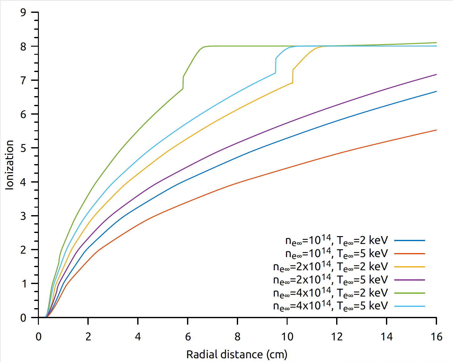
In this Section, we study the influence of atomic processes such as multiple ionization of neon and dissociation and ionization of deuterium on the pellet ablation. The degree of ionization is very low in proximity to the surface of the pellet (mostly neutral atoms) and it becomes progressively higher further downstream as the temperature, and thus thermal ionization, steadily increases as is seen in figure 3 for neon (Z=10). We use the term average ionization level interchangeably for the electron fraction in the cloud . For high-Z pellets, multiple ionization levels introduce energy sinks that influence strongly the temperature and in turn the conductivity of the cloud. We report in this subsection 1D spherically symmetric results when atomic processes are allowed in the ablation cloud and compare the ablation rate and flow states with the ideal gas case.
In figure 3 the dependence of the ionization level on the plasma parameter is displayed. The ionization level grows with plasma density but decreases with plasma temperature . From the NGS scaling laws, the mass flow follows the plasma electron density trend, scaling with , but is more sensitive to the temperature, scaling with . As both of these parameters increase, the ablation rate and cloud temperature increase. However, since is more sensitive to an increase in , for a fixed value of , the increase in temperature in the cloud is not sufficient to overcome the increase in and the cloud becomes denser and more difficult to ionize. The reverse is true for a fixed value and increasing .
| mm | 25.60 | 117.0 | 256.7 |
| mm | 64.53 | 295.4 | 649.4 |
| mm | 347.3 | 1591 | 3512 |
| mm | 25.83 (+0.9) | 118.3 (+1.1) | 271.5 (+5.8) |
| mm | 65.58 (+1.6) | 301 (+1.9) | 680.9 (+4.8) |
| mm | 338.3 (-2.7) | 1606 (+0.94) | 3603 (+2.6) |
| mm | 32.57 | 148.9 | 328.5 |
| mm | 81.71 | 374.3 | 826.3 |
| mm | 438.4 | 2011 | 4445 |
| mm | 33.19 (+1.9) | 155.4 (+4.4) | 350.1 (+6.7) |
| mm | 82.53 (+1) | 387.1 (+3.5) | 859.2 (+3.8) |
| mm | 398 (-9.2) | 1932 (-3.9) | 4279 (-3.7) |
| mm | 41.52 | 190.2 | 419.6 |
| mm | 103.7 | 475.2 | 1050 |
| mm | 553.2 | 2536 | 5610 |
| mm | 42.52 (+2.4) | 202.2 (+6.3) | 455.8 (+8.6) |
| mm | 101.9 (+1.7) | 490.0 (+3.1) | 1113 (+6.0) |
| mm | 461.7 (-16.5) | 2277 (-10.2) | 5267 (-6.1) |
The trend emerging from tables 7(b), 7(d), 7(f) is that for small pellets ( mm), the relative change in the ablation rate due to atomic processes actually increases as the heat flux intensity grows (due to an increase in and/or ). For bigger pellets, the trend is reversed and we observe sizable reduction in the ablation rate at high plasma densities. For a fixed plasma electron density, the relative increase in ablation rate for small pellet is greater at high plasma temperatures, conversely for bigger pellets the reduction in is more important at low plasma temperatures. This effect grows markedly with the plasma density .
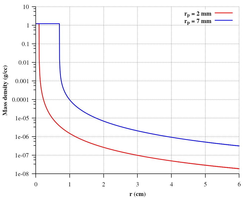
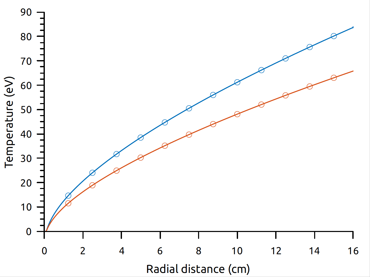
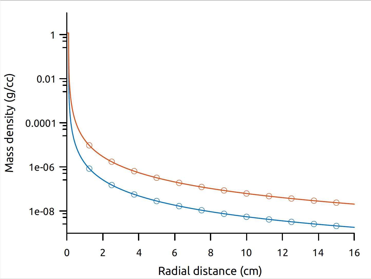
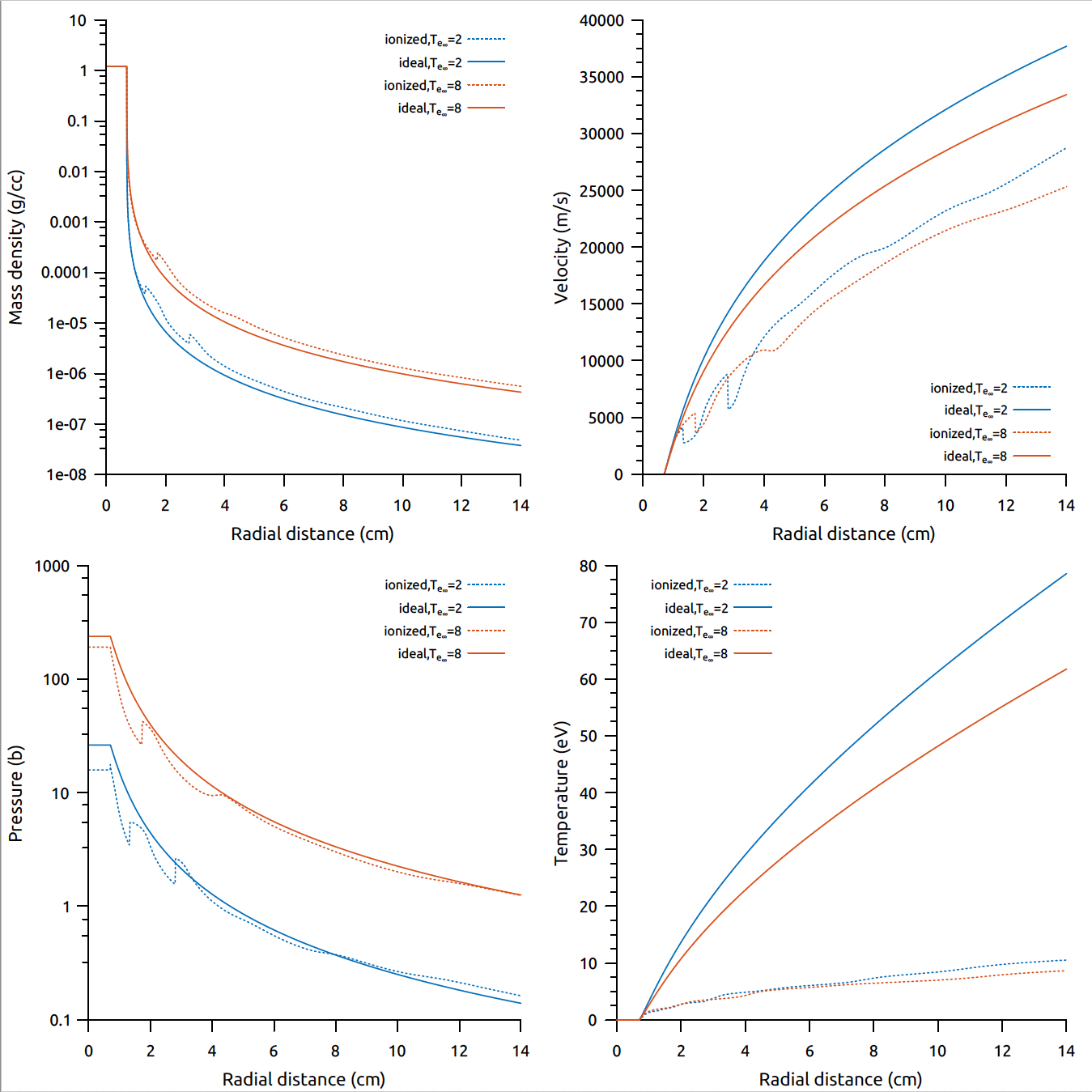
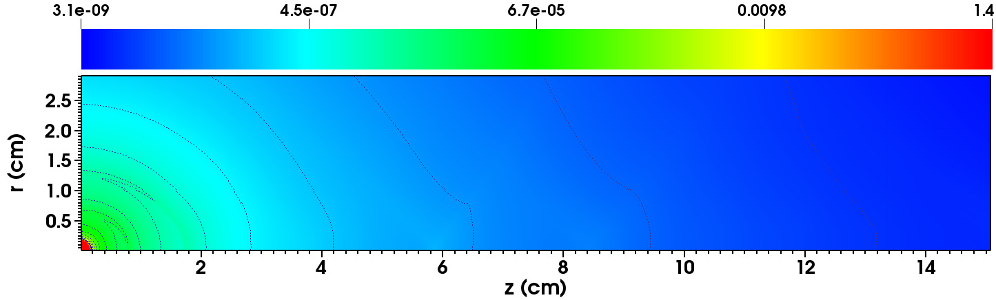
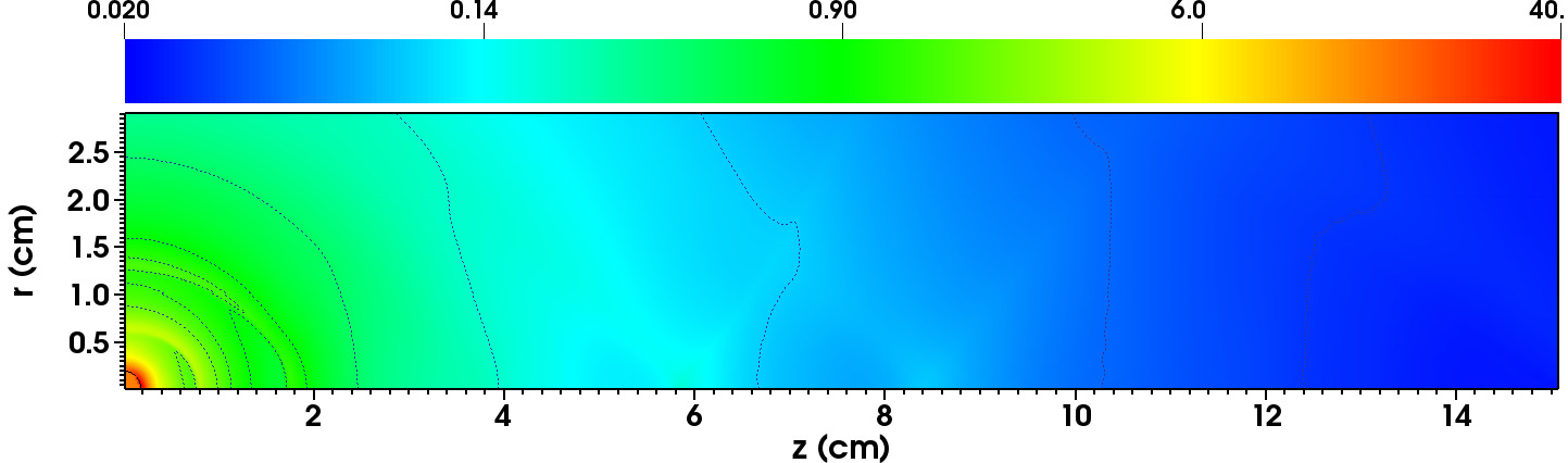
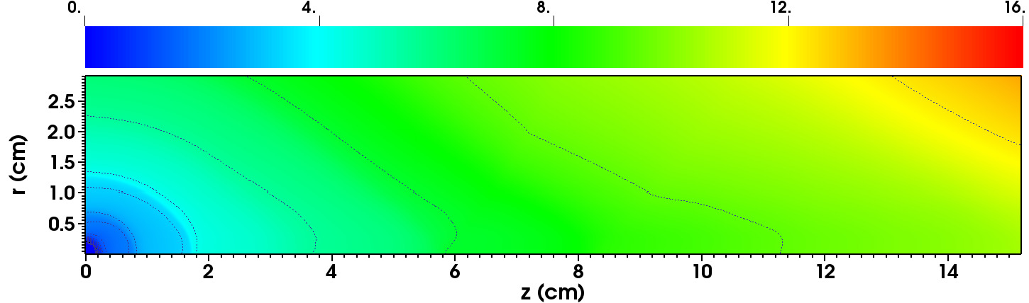
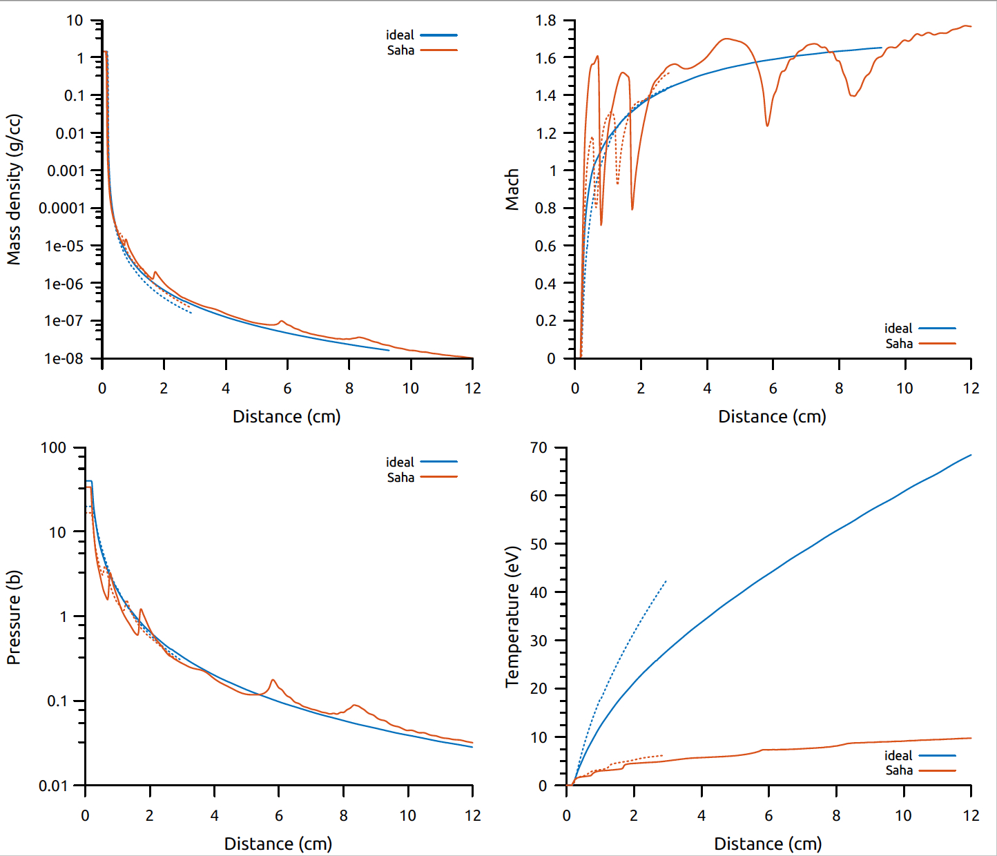
The radial flow states profiles (density, pressure, temperature, velocity) are plotted in figures 4(a), 4(b), 5(a), 5(b) for varying pellet radii , plasma electron density and temperature . For each flow variable, the plotted profiles were obtained from the ideal EOS (no atomic processes, solid line) and LTE EOS with atomic processes (dashed line).
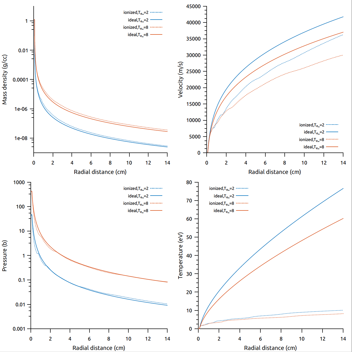
For a pellet of radius mm, when cm-3 (figure 4(a)), the cloud states varies smoothly along the cloud for both EOS and plasma temperatures. The density is consistently higher in the ionized cloud. However, the energy sinks introduced by the ionization potentials lower the thermal and kinetic energy, the temperature is decreased almost eight times in the ionized cloud and the velocity reduction is close to 1.5. The differences in these profiles increase slightly with .
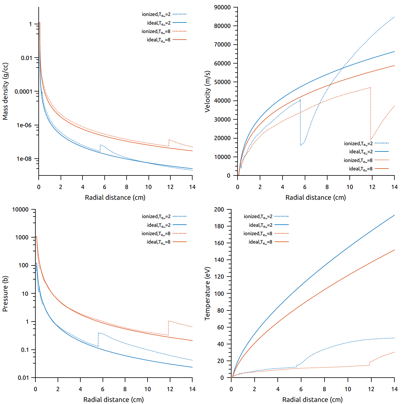
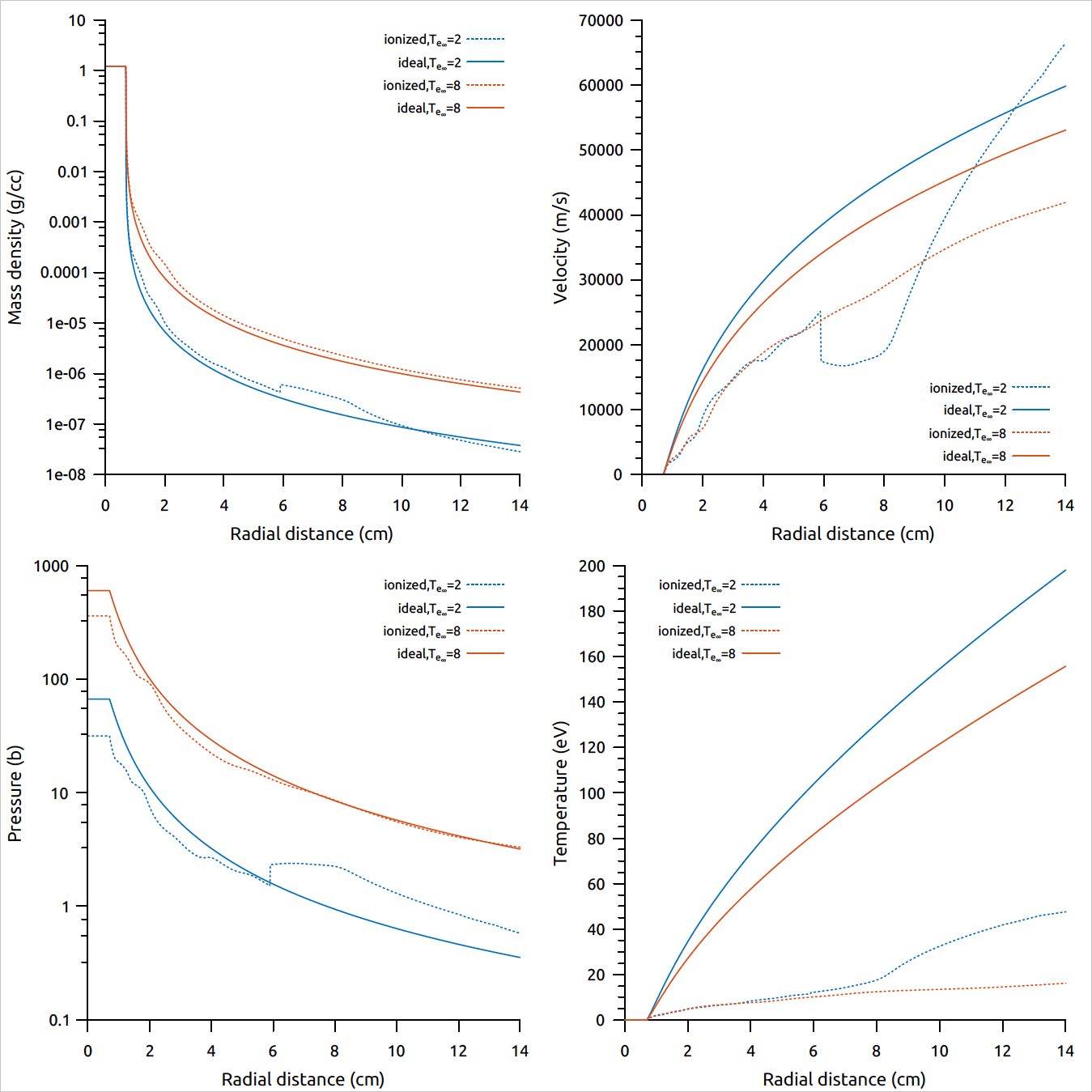
In figure 4(b), the plasma density is increased to cm-3. The degree of ionization is higher in this case throughout the cloud compared to cm-3 as can be seen in figure 3. As a result, the energy sinks become deeper and lead to the formation of a strong shock in the flow (at cm for keV and cm for keV). The shock is pushed downstream as increases since the corresponding ionization level is also reached further downstream. In the region , the flow exhibits the same behavior as in figure 4(b). For a small radius pellet, the reduction in velocity is not sufficient to overcome the increase in density and to lower the ablation rate.
We now turn our attention to the influence of atomic processes on the ablation rate of a molecular deuterium pellet: , , . For cryogenic pellets, Ishizaki et al. in Parks_Ishizaki04 found that inclusion of atomic processes lowered the ablation rate by a few percents. This calculation was confirmed in Samulyak07 . We performed similar simulations to verify the implementation of our pellet code against those results. The numerical EOS for partially dissociated and ionized deuterium plasmoid implemented in the pellet code is similar to that of neon. The only differences stem from the multiple ionized states of neon (Z=10) compared to deuterium (Z=1) and the dissociation events to which are subjected molecules. The thermodynamic quantities of interest, pressure and energy, are derived in Parks_Ishizaki04 . Similarly to the neon case, logarithmic tables for the dissociation and ionization fractions were created over a relevant range in several sets of thermodynamic quantities. These tables were accessed and interpolated during the runs eschewing the need to solve two non-linear LTE Saha equations at each location and for each time step.
At this point, we caution the reader that the electronic heat flux used in these works were slightly different than what has been described in section II.3. Our numerical experiments for this verification was performed using the kinetic model developped in Parks_Ishizaki04 and the same parameters: mm, cm-3 (no electrostatic shielding), keV. For an ideal ablation cloud Ishizaki et al. reported g/s and Samulyak et al. reported g/s. For this case we found g/s.
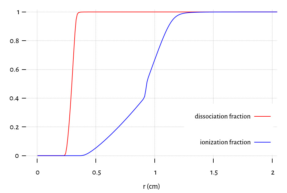
The atomic processes for molecular include dissociation of the molecules into atoms upon absorption of the dissociation energy eV. These deuterium atoms can then be ionized (with ionization energy eV). The resulting cloud consists of partially dissociated molecules and partially ionized atoms. The dissociation fraction and ionization fraction are found locally from the solution of two Saha equations in complete analogy with the system of Saha equations for multiply ionized states in the case of neon. When both dissociation and ionization are accounted for, Ishizaki et al. reported a reduction in the ablation rate, g/s. Similarly Samulyak et al. found g/s. We report g/s, which is a reduction of , in agreement with Ishizaki and Samulyak ( and respectively). An interesting result that emerged from this set of verifications, and which has been theorized by Felber et al. in Felber_1979 , was that dissociation was the only contributing factor to the reduction of the ablation rate. Indeed, in simulations ignoring ionization of dissociated atoms and only allowing dissociation of molecules in the cloud, we observed a slightly steeper reduction in the ablation rate, g/s, confirming the trend observed in tables 7(b), 7(d), 7(f) for neon that ionization tend to increase the ablation rate for small pellets. Because the ionization potential of is almost three times the dissociation energy for the dense gas layer shielding the pellet and controlling the ablation rate is essentially completely dissociated before any ionization effects come into play. A sufficient portion of the incoming electron energy is absorbed and used for dissociation in this layer, which in turn reduces the available energy for vaporization.
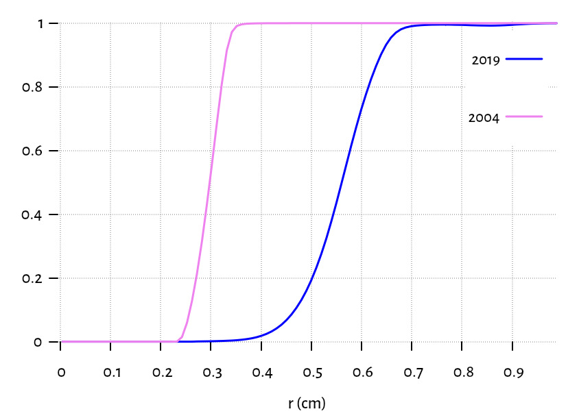
This observation can be compared to simulations carried out with the 2019 updated kinetic model of Parks for the heat flux. Using the same plasma and pellet parameters as before, the ideal cloud mass flow is g/s, the mass flow when only dissociation is allowed is g/s and when dissociation and ionization are allowed g/s. Here the effects of atomic processes are negligible compared to the ideal case. As shown in figure 9 the region where most of the dissociation energy is absorbed is much wider and further from the pellet with the updated heat flux model than with the heat flux model used in Parks_Ishizaki04 .
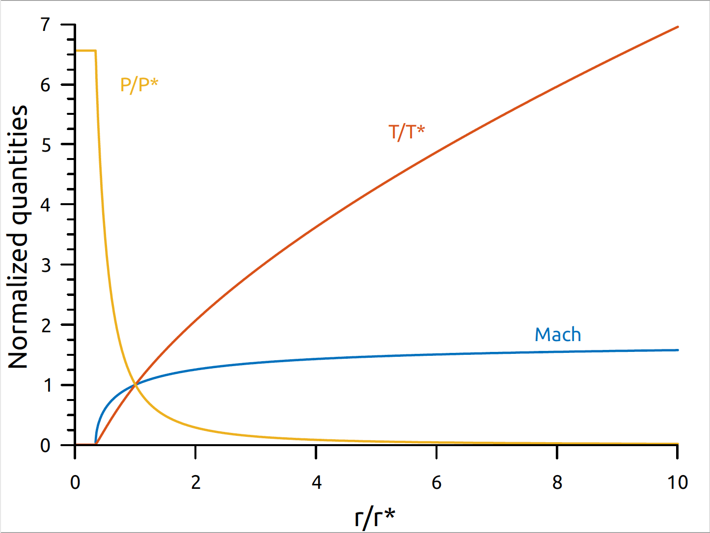
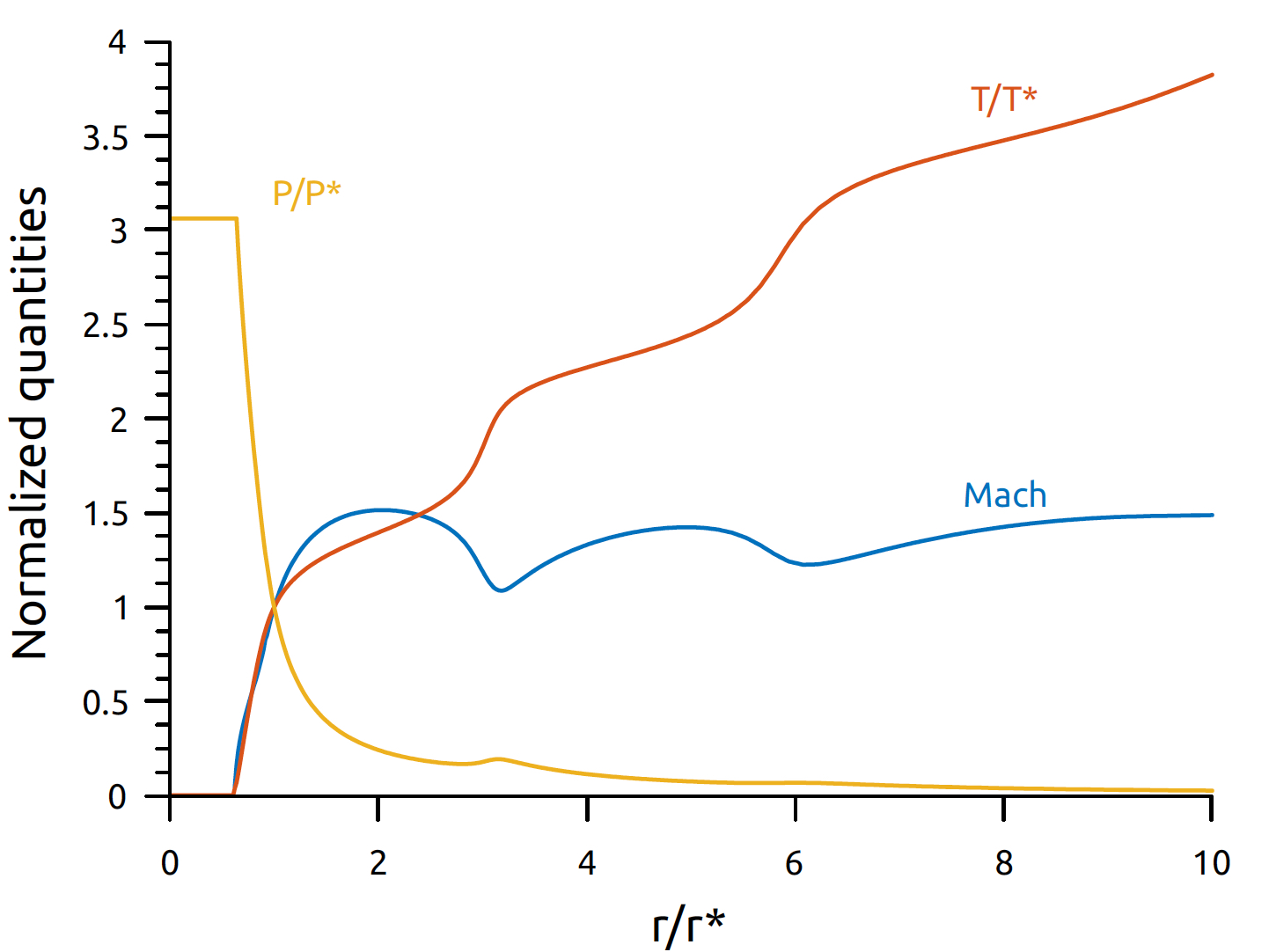
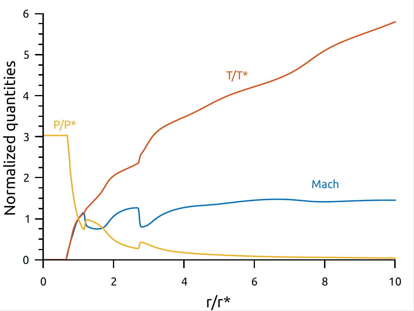
We close this section with an analysis of dimensionless profiles for neon pellets when ionization in the cloud is permitted. The flow is subsonic near the pellet, the heat flux from the plasma electrons accelerates the flow, at the sonic point the expanding cloud balances the effect of heating and the flow becomes supersonic. When ionization is permitted, a fraction of the energy of the incoming electrons is used for ionization rather than for thermal and kinetic energy. The presence of energy sinks in the cloud due to ionization losses reduces the temperature and decelerates the flow (figure 6(b)). If enough energy is lost for the ionization of neon atoms, the flow velocity drops to subsonic values (figure 7). The formation of a shock wave constrasts with the smooth flow profiles obtained when using an ideal gas EOS with continuous heating (figure 6(a)). Behind the shock, the pressure and temperature jump and the flow is re-accelerated. When the plasma number density is increased, more energy is deposited in the cloud, the degree of ionization corresponding to sufficient energy loss for shock formation are reached earlier (see figures 3, 7) and the first shock front sits closer to the pellet surface. This has also been observed for hydrogen pellets Parks_Ishizaki04 ; Samulyak07 . High-Z pellets however, allow for the possibility of multiply ionized states, which introduce multiple energy sinks and results in multiple shock fronts in the flow. In figure 7), a second shock further downstream is observed. This secondary shock is located two Mach radius away from the first shock. Atomic processes introduce marked effects on the flow dynamic, which follow the same trend for a wide range of pellet and plasma parameters. This can be contrasted with the influence of atomic processes on the ablation rate, which trend does depend on the pellet size and the plasma parameters (see tables 7(b), 7(d), 7(f)).
IV.1.2 Axisymmetric approximation
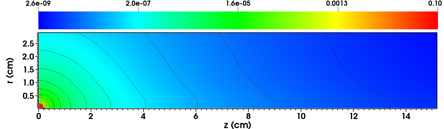
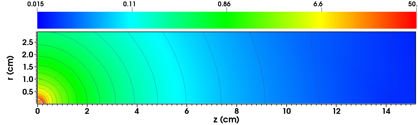
We now turn our attention to the 2D cylindrical axisymmetric model for the ablation of a single pellet. In what follows, we probe the effect of anisotropic heating on the cloud dynamic and the ablation rate. To allow comparison with the spherically symmetric case, we performed simulations with and without ionization in the cloud. The canonical parameters we used for the remaining of this work are: mm, keV and 1/cc. The action of the force on the ablatant cloud is not included in this section but will be investigated next, in Section IV.2. For now, the only effect of the magnetic field is to direct the hot electrons along the -axis. We remind the reader that we consider a rigid pellet, the interior fluid states inside the pellet are constant with zero velocity, and only the surface states are updated according to the surface ablation model. The states distribution in the 2D region are plotted at steady state in figures 10 and 11. To compare the properties of the flow in the longitudinal and radial direction, the corresponding profiles are plotted in figures 12. The dark curve near the origin in the figures below is the pellet surface. It should also be noted that in the absence of the Lorentz force to constrain the cloud along the field lines, the cloud/plasma interface is free to expand unrestrained and eventually exits the compuational domain, which is why it is not visible anymore in figures 10 and 11.
Hydrodynamic ideal model
The 2D states distribution of the hydrodynamic ideal model (neither MHD nor ionization is included) are presented in 10 and the radial and longitudinal profiles are plotted in 12. In this case, even if B=0, the expansion is essentially two dimensional due to the longitudinal direction being the imposed streaming direction of the plasma electrons. However, it was shown in Parks_distorsion that the parallel heat flux is approximately independent of the polar angle resuting in the flow quantities being approximately spherically symmetric.
The steady state is reached after approximately 30 s and we record an ablation rate of 45.8 g/s. This corresponds to a decrease in the ablation rate compared to the 1D spherical symmetry with identical plasma parameters (see table 7). At steady-state, the shape of the cloud is close to spherical but stretches out in the longitudinal direction. Similar to the 1D case in figure 6(a), the flow smoothly transitions from subsonic to supersonic across an ellipse-shaped sonic surface with the major axis mm and the minor axis mm. Figure 12 shows that the density distribution is isotropic over the pellet surface before falling more quickly in the radial direction. The pressure distribution is not uniform over the pellet surface and it is larger at the poles ( 40 bars) compared to the equator ( bars).
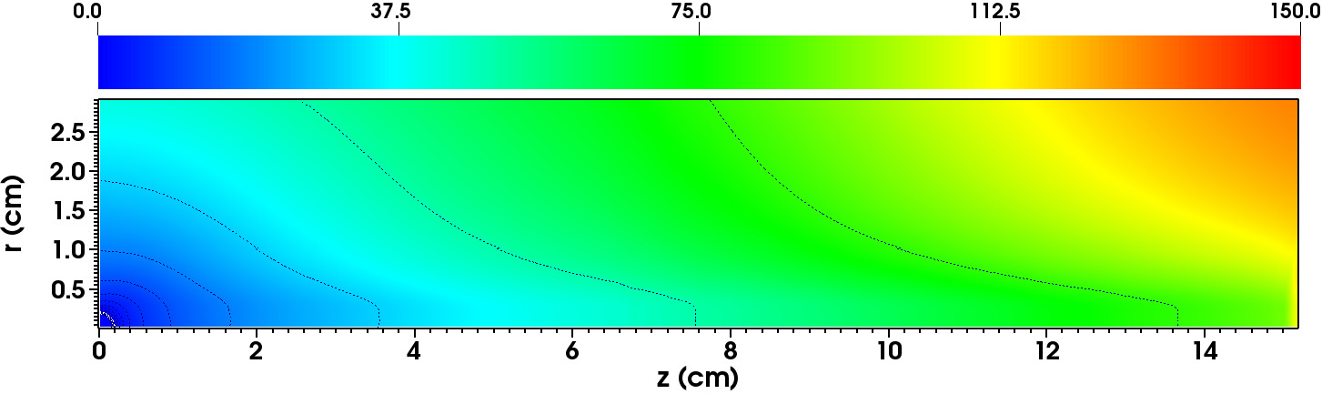
The pressure falls sharply within a small region along the -axis to reach values similar to that at the pole; the pressure distribution then becomes nearly isotropic in the rest of the cloud 10(b). The surface pressure differential was also observed in Parks_Ishizaki04 where they reasonned that the build up of ablated material at the poles, where the heat flux is fully absorbed by the pellet as opposed to the equatorial points where incoming electrons stream by unimpeded by the pellet, was responsible for the non-uniform pressure distribution. The temperature along the z-axis is less everywhere than along the radial direction. As explained in Samulyak07 this is due to pellet shadow. The region is heated by incoming electrons streaming along the positive -axis only: electrons streaming from the opposite direction are completely absorbed by the pellet when they reached the surface and do not participate in the heating of the region behind the pellet. In the rest of the domain, where , the cloud is heated from electrons streaming in both directions.
Hydrodynamic model with atomic processes
The hydrodynamic ideal model did not allow ionization in the cloud. We now report simulation results where ionization of the neon gas is enabled by shifting to the EOS model describe in Section II.2.2. The steady-state is reached in 50s, and the corresponding state distribution are plotted in figure 11. For this case, and in the absence of MHD forces, we record an ablation rate of g/s corresponding to a reduction compared to the 1D model in table 7(b). This is consistent with the effect of anisotropic heating on the ablation rate in the ideal case described in the previous paragrah. Ionization increases the ablation rate by 3% compared to the 2D hydrodynamic ideal model, twice as much as the increase in the 1D spherically symmetric approximation (table 7). The shape of the cloud remains almost spherical with the contour lines of state variables being nearly spherical. The flow experiences distinct shocks and five transonic regions. The sonic surfaces are ellipsoidal except for the first one, closest to the pellet, which is practically spherical. The density (figure 12) is uniform over the pellet and follows the ideal gas density distribution. The surface pressure continues to exhibit a differential over the pellet with values slightly inferior to the ideal gas. The temperature is about seven times lower in this case compared to the ideal case, and the radial and longitudinal temperature profiles reveals that although it is present, the effect of the pellet shadow due to anisotropic heating is greatly reduced. The lower temperature of the cloud is due to energy sinks introduced by the multple ionization events and radiation cooling, both of which are absent in the ideal case.
IV.2 Ablation studies with axisymmetric MHD model
In this Section, we study the influence of the force on the pellet ablation flow. The cloud becomes ionized and conductive, the Lorentz force drives the ablation cloud along the direction of the magnetic field creating an ablation channel parallel to the -axis. As is the case for hydrogenic pellets, we expect this phenomenon to be dependent on the plasma parameters, magnetic field and pellet radius. In Samulyak07 it was found that for deuterium pellets the warm up time, i.e a simulation parameter used to mimic the ramping up of the magnetic field and incoming electron heat flux as seen by the traveling pellet, to be a sensitive parameter in the formation of the ablation channel. We conducted a series of numerical experiments to assess the sensitivity of the neon cloud evolution to this parameter. The values that we sampled for the warm up time ranged from a few microseconds to several hundred microseconds, however we found the ablation channel and steady-state ablation rate to be independent from this parameter. To reduce the simulation time, we use 10 s warm-up time. We impose an effective shielding length of 15 cm; past that mark the electron heat flux is cut off and the fluid is allowed to escape the computational domain via an outflow boundary condition. This effective shielding length is necessary for establishing a non trivial steady-state solution to eq.1 as is explained below.
Making use of the approximation that the inertial terms in the radial force balance are negligibly small in the ablation channel part of the flow field where the magnetic field inhibits radial expansion, the continuity and momentum equations in eq.1 can be reduced to a single convective-diffusion equation. Solving this equation shows that steady-state is not possible due to the fact that the longitudinal integrated density along the symmetry axis passing through the pellet, or optical depth , would be infinite if the flow field were to reach steady state. Consequently, the incident plasma electrons would be completely shielded and the pellet would cease to ablate, contradicting steady-state premise. Thus the upper limit on the opacity integral should be finite. However, a finite opacity (cloud length) is only possible if we invoke 3D effects such as polarization drift of the ablation cloud caused either by the pellet motion itself or the grad-B drift drive. These effects that shift the elongated ablation channel off the pellet axis and lead to an effective cloud length will be investigated in the future using full 3D simulations.
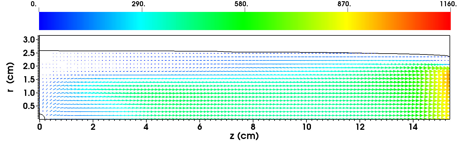
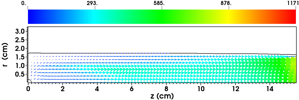
We present results for the field strength of 2, 4, 6 and 9 Tesla and fixed canonical plasma parameters: keV, 1/cc and mm. The formation of an ablation channel is the main difference compared to the nearly spherical expansion of cloud in the hydrodynamic case. The flow starts out nearly spherical and remain quasi-spherical close to the pellet throughout the computation. As the ablated material flows downstream (a few pellet radii) it quickly evolves into a cylindric channel symmetric with respect to the longitudinal axis. This is due to the combined effect of the streaming hot electrons ionizing the ablation cloud and the magnetic field lines redirecting the flow in the direction of along the -axis. The flow redirection is observed on the velocity vector field in figure 18, 23,28,33 for increasing field values.
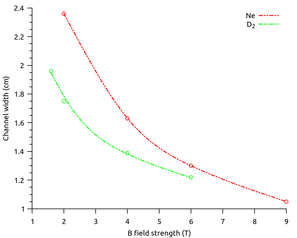
| 2T | 4T | 6T | 9T |
| 2.59 cm | 1.75 cm | 1.07 cm | 1.02 cm |
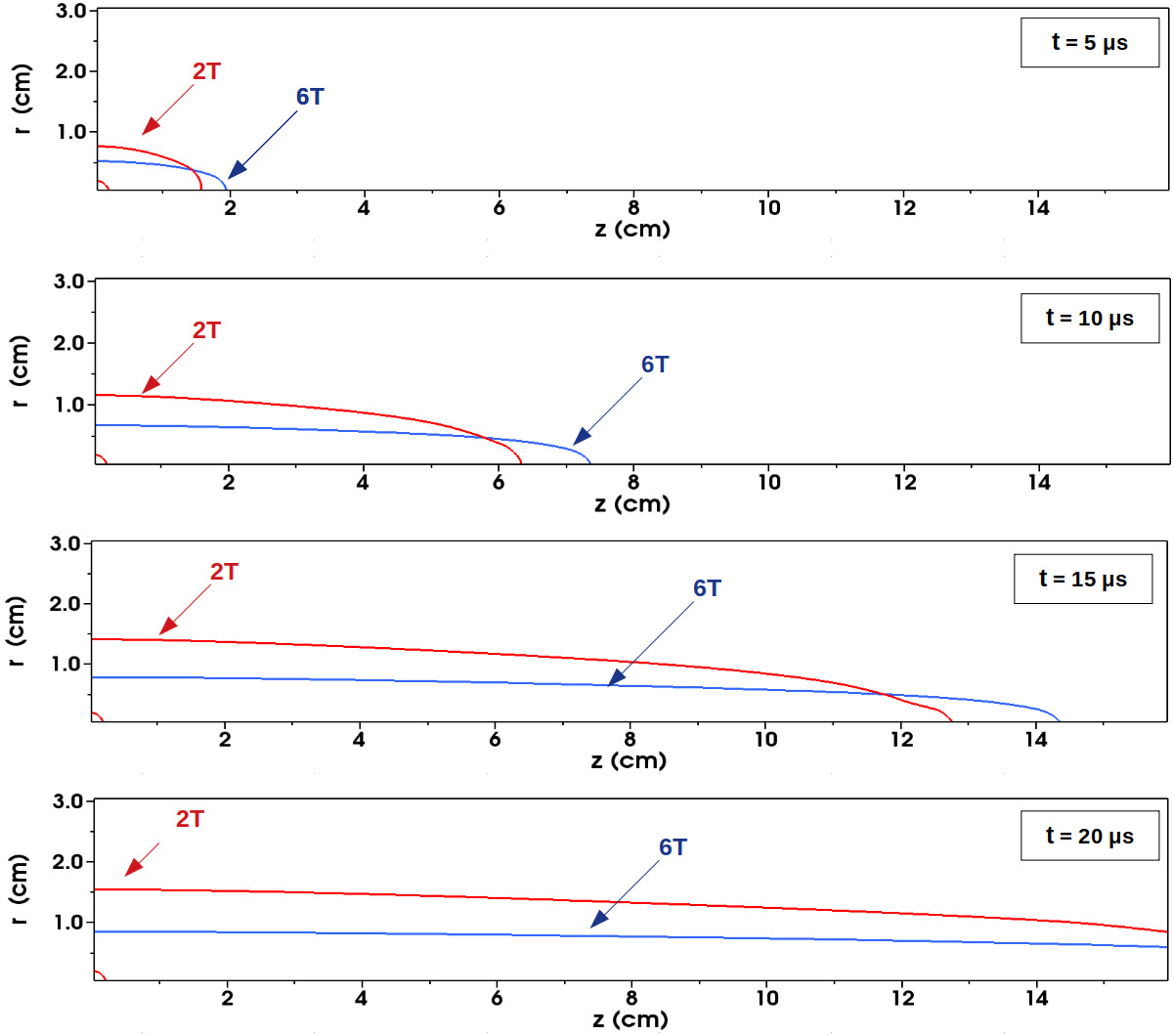
The establishment of the ablation channel for a neon pellet during the first s is shown in figure 13 for T and T. The cloud starts loosing its spherical shape in the first s and begins to reorient itself along the magnetic field lines. Near the pellet, the neutral cloud flow remains spherical. In table 8, we record the channel width for varying field strengths. The channeling of the flow is sensitive to the strength of the magnetic field as can be seen in figure 14. At low field strengths, the channel narrows rapidly as the field is increased and undergoes a contraction of 32% when the magnetic field increases from 2T to 4T. The contraction levels off at higher field strengths, the channel width is decreased by when the magnetic field changes from 6T to 9T.
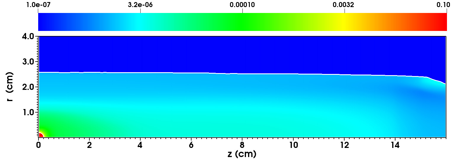
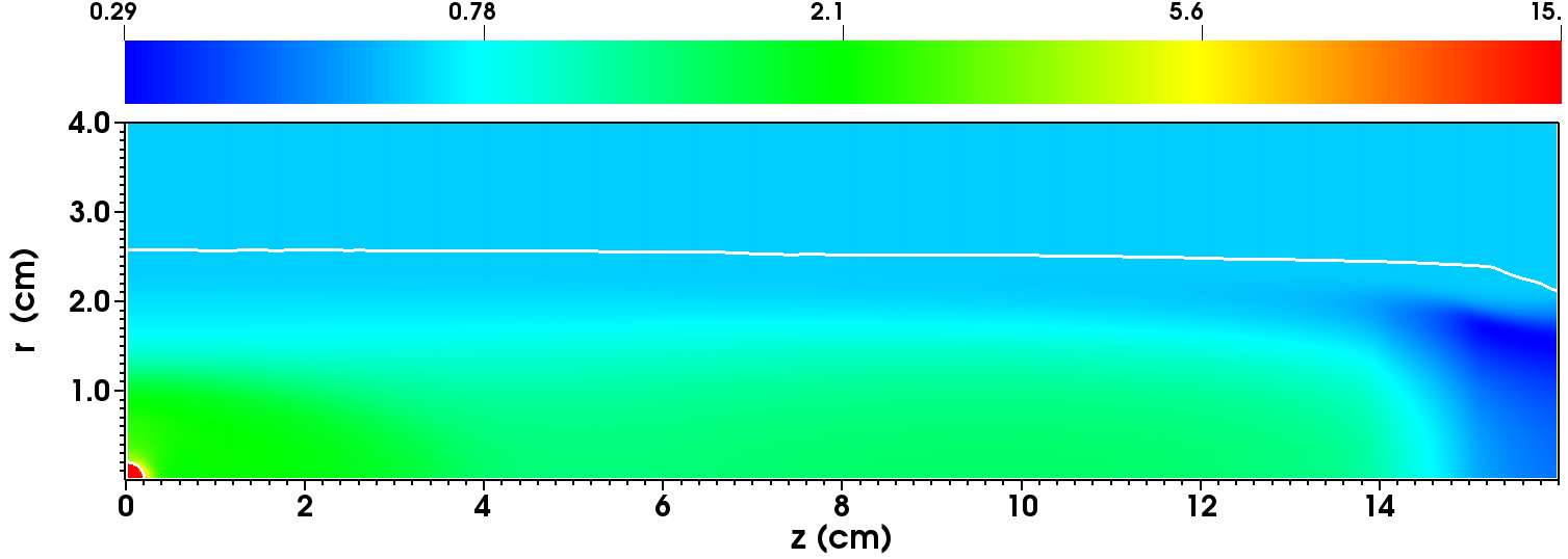
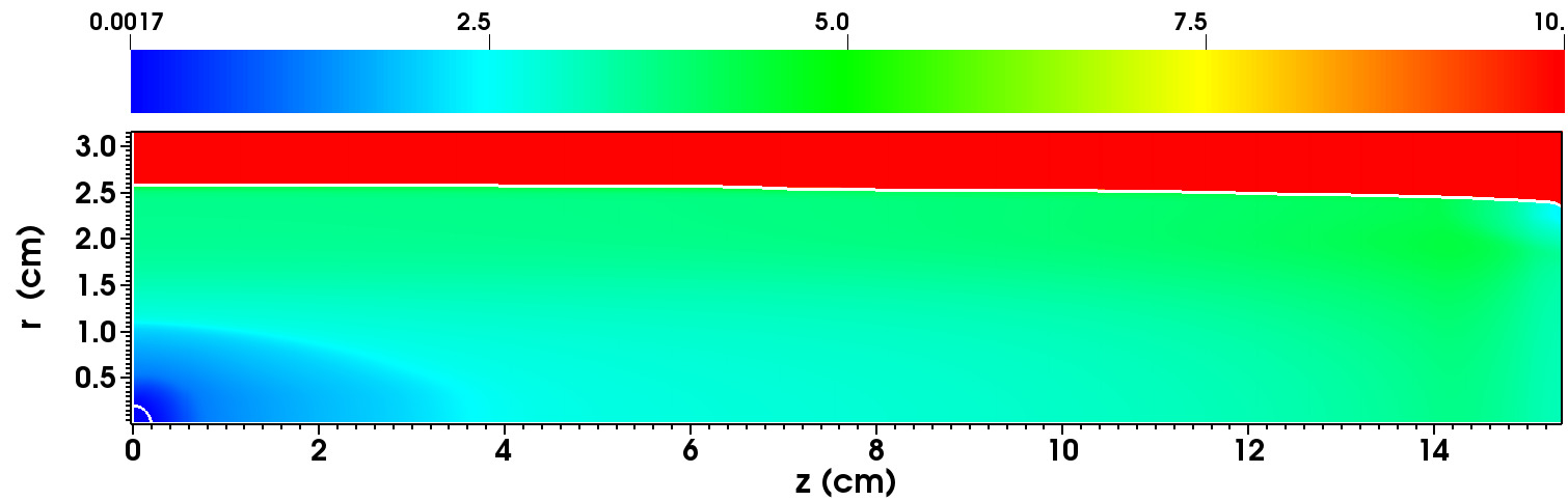
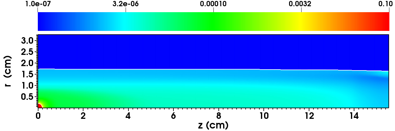
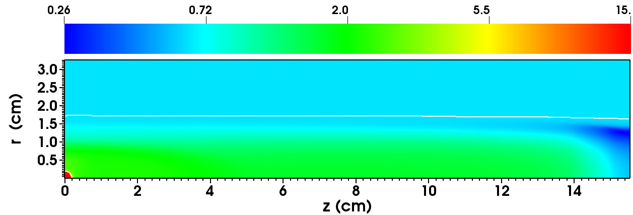
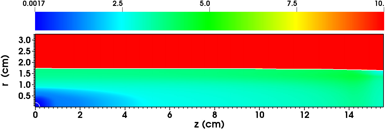
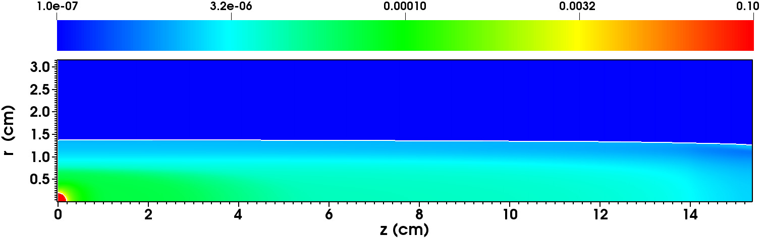
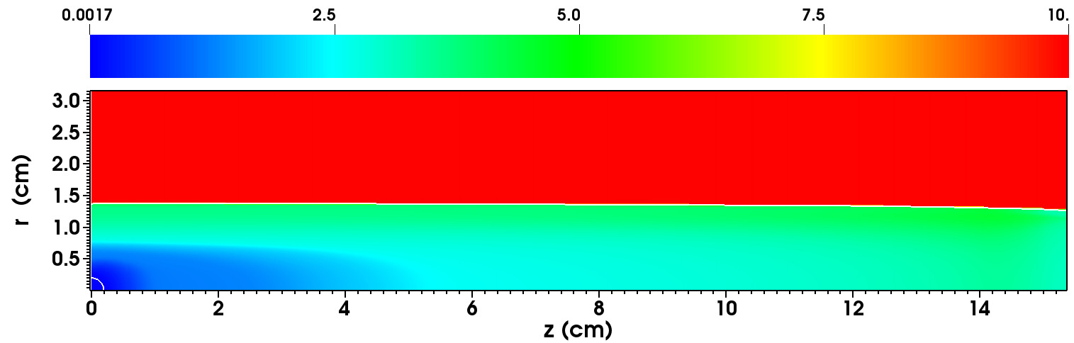
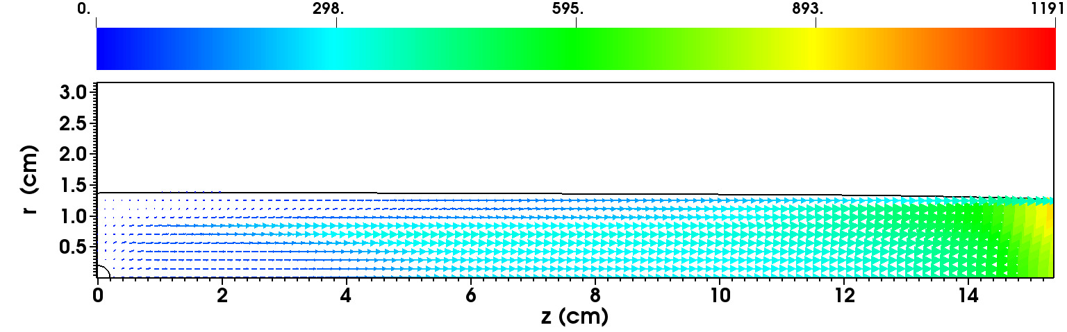
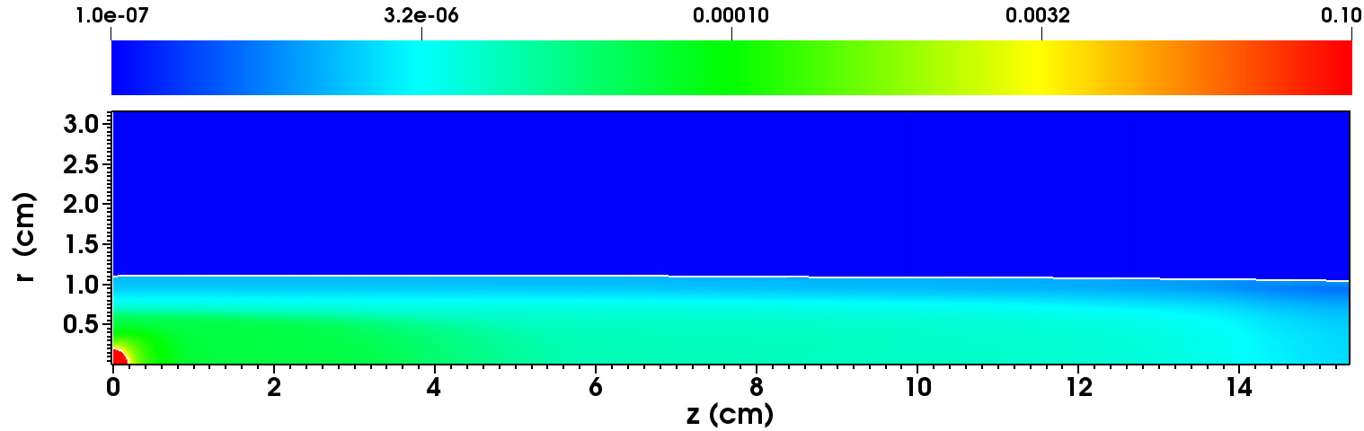
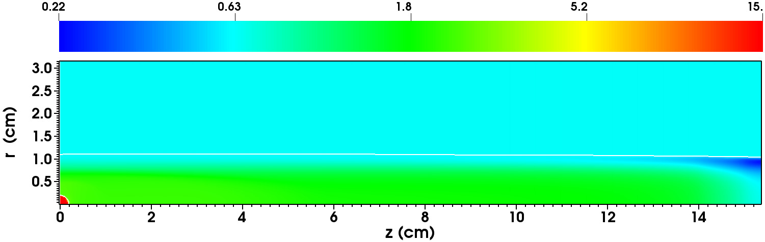
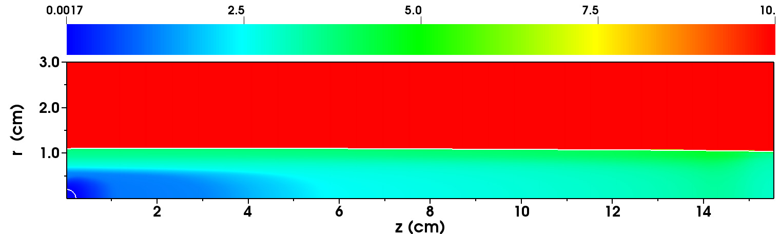
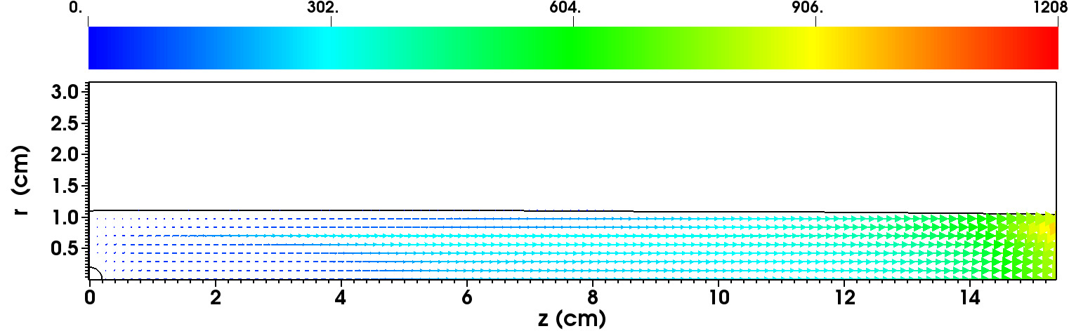
The 2D distributions of flow field variables, plotted in in figures 19, 24,29, 34, show the structure of the ablation flow. The explicit tracking of the cloud boundary (represented by the white, almost straight, line in the 2D plots) was found to be necessary to unequivocally determine the location of the ablated material, and, as result, to evaluate the channel width. In accordance with the treatment of the interface as a propagating contact discontinuity, the pressure across the boundary is continuous, while the density, temperature and radial velocity are discontinuous.
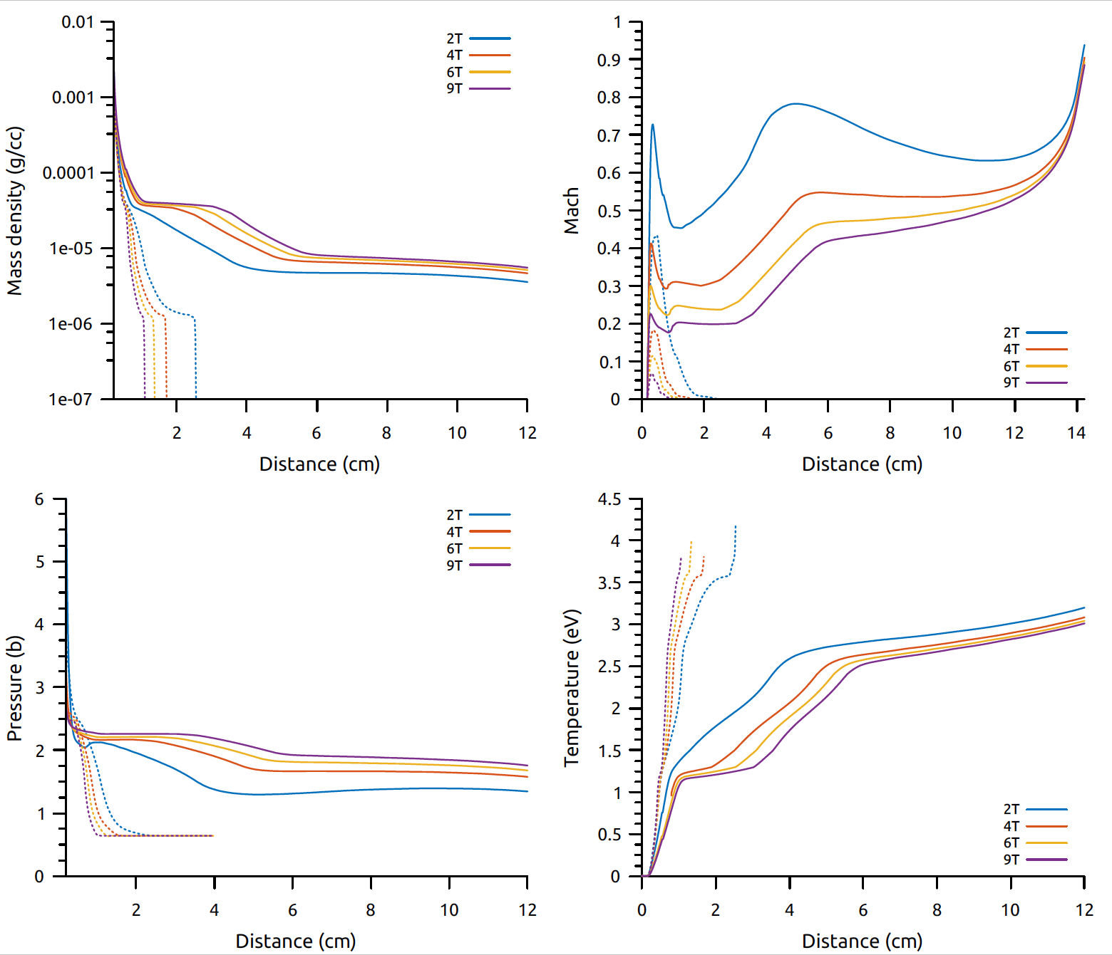
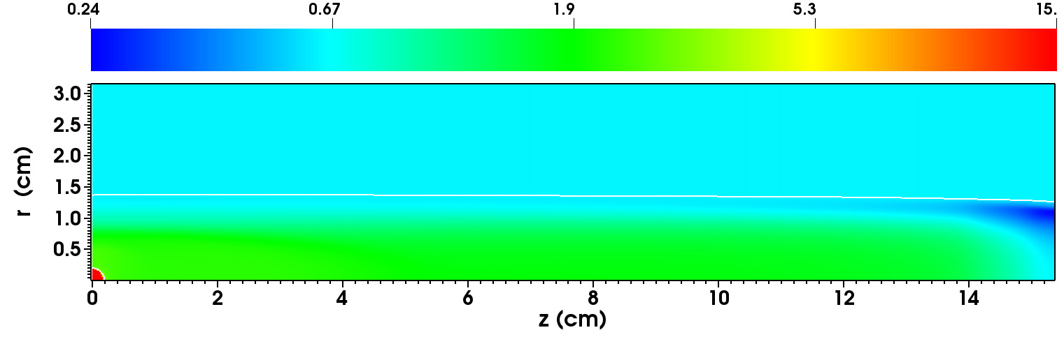
Radial (dashed) and longitudinal (solid) profiles of the ablation flows are presented in figure 35(a). The sudden drop in the radial density profiles indicates the edge of the channel. Very close to the pellet, as remarked above, the flow variables are similarly distributed in both directions. The density and pressure fall rapidly in the radial direction while the temperature increases. For any value of B, the pressure falls smoothly to that of the background plasma bars with a steeper descent gradient at higher field strengths. The longitudinial pressure tend to an almost constant value in the ablation channel (with a very weak wariation) as the magnetic field increases. The T case shows a negative pressure gradient from the pellet surface extending to 4 cm and stabilizing at the (almost) constant pressure 1.35 bars. Pressure gradients inside the channel tend to vanish as the field strength is increased. When T, we can see that the pressure is constant at 2.25 bars in the region extending from the pellet surface to 4 cm. A weak pressure gradient then brings the pressure at 2 bars and then very slowly tapers off. Similar effects of the B field are observed on the longitudinal density profiles. For T, the mass density rapidly decreases from the pellet surface until 4 cm and remains almost constant at g/cm-3 = cm-3 until the end of the channel. The T simulation shows that after a strong negative gradient at the surface, the density is almost constant from 1 cm to 4 cm with value g/cm-3 ( cm-3). After a rarefaction region between 4 and 6 cm the density seems to be stabilizing around g/cm-3 = cm-3. The pressure and density are also uniformly higher as the ablation channel contracts more and more under the effects of increasing MHD forces. The Mach number and the temperature display non linear behaviors, which are caused by ionization events starting a few millimeters away from the pellet, which reduce the kinetic energy of the flow. The Lorentz force squizes the ablation channel forcing a denser flow with higher sound speed and lower Mach number, as can be seen in the figure 35(a). The flow always remain subsonic preventing the formation of shocks, as opposed to the 1D spherically symmetric model or the hydrodynamic Saha model. It can also be seen that the radial Mach number is consistently at most half the value of the longitudinal Mach number. We observe the stagnation point in the transverse direction on the z=0 midplane which coincides with the ablation channel radius and where the velocity . This is in agreement with Parks_1991 ; Samulyak07 . The temperature increases in both directions and just like in the hydrodynamic case, the pellet casts a shadow reducing the heat deposition behind it. This difference between transverse and longitudinal temperature becomes more pronounced as the field strength is increased.
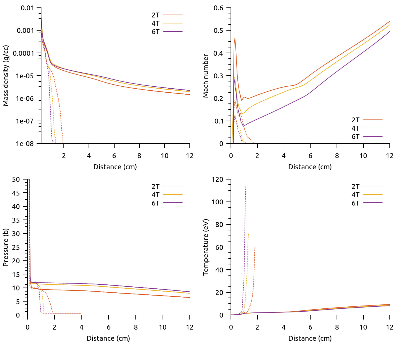
The radial and longitudinal profiles for ablating pellets are shown in figure 35(b) . These plots confirm the observations made for a neon pellet concerning the response of the ablated flow to the action of the force. The flow density experiences a strong gradient at the pellet surface until cm and then continues to decrease slowly in the channel. This is to be contrasted with the density profiles for , which undergo regions of constant density (from cm to 4 cm) and again from cm until the exit. The channel is more narrow for and the radial density falls off rapidly. The mean densities for both materials have also comparable values. This is not the case for the pressure distribution, which has higher values for pellets. For T, the mean pressure in the channel is bar for and bar for , and for T, bar and bar for and , respectively. The slow and constant decay of the density in the field direction is accompanied by a similar decline in the pressure profile. Finally, we note that the cloud keeps its pressure in the radial direction; it is only near the cloud edge that the pressure plunges to the background plasma pressure . This effect is more pronounced as the field increases. The pellet cloud is also hotter than the corresponding neon cloud. Main differences between neon and pellet clouds are explained by the absence of volume radiation in deuterium, as well as by the multiple ionization potentials of neon. The high temperatures in the channel for pellets also leads to heighten sensitivity to small numerical errors not seen for pellets (figure 36, 14).
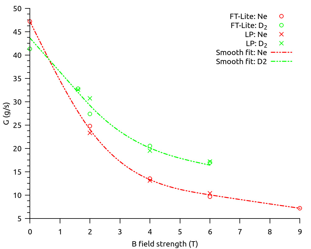
Finally, we summarize our studies of the reduction of neon and deuterium pellet ablation rates in magnetic fields in tables 9,10 and in figure 36. FronTier results are compared with fully three-dimensional simulations performed with the Lagrangian particle pellet / SPI code Samulyak_IAEA_2020 . For the code comparison purpose, the grad-B drift model in the Lagrangian particle code was turned off and the same fixed shielding length of the ablation cloud was imposed. Both codes are in good agreement for both pellet materials over the magnetic field range from zero to 2 T. Simulation results of both codes are shown with discrete points, and the continuous line was obtained by an optimal polynomial fit to the numerical data. Both codes predict strong reduction of the ablation rate in magnetic fields of increasing strength, caused by increased densities in narrower ablation channels, increasing the pellet shielding, and lower ablation flow velocities. The reduction rate is the most significant at low values of the magnetic field.
| (T) | (g/s) | (g/s) |
|---|---|---|
| 2 | 24.8 | 23.3 |
| 4 | 13.5 | 13.1 |
| 6 | 9.68 | 10.4 |
| (T) | (g/s) | (g/s) |
|---|---|---|
| 1.6 | 32.8 | 32.6 |
| 2 | 27.4 | 30.7 |
| 4 | 20.5 | 19.5 |
| 6 | 17 | 17.2 |
V Conclusion
In this work, near-field physics processes relevant to the pellet ablation problem in the context of plasma disruptions mitigation and refueling have been studied numerically using the pellet model based on the FronTier code. The pellet model resolves the pellet surface ablation, the formation of a dense ablated cloud, the anisotropic heating from deposition of hot plasma electrons along magnetic field lines, the ionization of the cloud and redirection of the flow under the effects of MHD forces. Owing to the plasma and pellet parameters considered in this work, we developed a numerical model where MHD effects near the pellet are resolved in the low magnetic Reynold’s number approximation () and where conditions away from the pellet support the low magnetic assumption. The kinetic heat flux model of Parks, updated for neon and deuterium, was implemented as well as a recent conductivity model for the partially ionized ablation cloud of a noble impurity pellet.
A tabulated LTE equation of state based on solutions of the Saha system for ionization fractions has been used for partially ionized neon and deuterium. To account for deviations from the ideal gas law in high-density, low-temperature ablated material near the pellet surface, a numerical EOS model based on Redlich-Kwong equations has been implemented. For the pellet sizes and plasma parameters considered here the Redlich-Kwong EOS had negligible effect on the ablation rate but we expect deviation from the ideal case to be important at high temperatures and densities of the background plasma and and small neon pellets where high surface pressure would develop.
Our pellet code is a client of the FronTier-Lite application programming interface, which refactors the front tracking libraries of the FronTier package. The resulting code is a lightweight computational software for MHD of free surface flows in the low magnetic Reynolds number approximation with interface tracking capability and ablating pellet physics specific routines. In particular, the code is able to resolve the pellet/cloud interface but also the cloud/plasma interface propagating them as contact discontinuities.
In the spherically symmetric approximation for neon pellets, the code has been validated against the improved NGS model which uses a kinetic solution of the electron distribution function to obtain the heat flux moment for incident Maxwellian electrons and for all light element pellets.in the spherically symmetric approximation in the case of neon. Furthermore, results obtained in Parks_Ishizaki04 ; Samulyak07 for deuterium pellets have been confirmed. Additional investigations on the influence of atomic processes have also been conducted and found that the reduction of ablation rates for neon pellets was significant only for larger pellets. Cross-validation of the two dimensional axisymmetric version of the code has been performed against the full 3D Lagrangian particle pellet code and satisfying agreement was obtained over a range of increasing magnetic field strength. Finally, simulation results using the two dimensional axisymmetric approximations have quantified the influence of MHD forces on the cloud evolution and predicted a strong reduction of steady state ablation rates in magnetic fields of increasing strength, suggesting longer pellet lifetime at higher field strength.
Future work will focus on the study of additional physical phenomena (grad B drift, rotation) in full 3D numerical models, the refinement of the EOS models to enable simulations of neon-deuterium mixtures, development and implementation of models for the heating of pellets by runaway electrons, and the resolution of multiple pellet fragments for the disruption mitigation system by shattered pellet injection (SPI).
Acknowledgement. This research has been supported by the DOE SciDAC Center for Tokamak Transient Simulations.
References
- (1) N. Commaux, D. Shiraki, L.R. Baylor, E.M. Hollmann, N.W. Eidietis, C.J. Lasnier, R.A. Moyer, T.C. Jernigan, S.J. Meitner, S.K. Combs, and C.R. Foust. First demonstration of rapid shutdown using neon shattered pellet injection for thermal quench mitigation on DIII-D. Nuclear Fusion, 56(4):046007, 2016.
- (2) D. Shiraki. Shattered pellet injection as the primary disruption mitigation technique for ITER. 26th IAEA fusion energy conference, Kyoto, Japan, 2016.
- (3) D. Shiraki, N. Commaux, L. R. Baylor, N. W. Eidietis, E. M. Hollmann, C. J. Lasnier, and R. A. Moyer. Thermal quench mitigation and current quench control by injection of mixed species shattered pellets in DIII-D. Physics of Plasmas, 23(6):062516, 2016.
- (4) V. Izzo. A numerical investigation of the effects of impurity penetration depth on disruption mitigation by massive high-pressure gas jet. Nuclear Fusion, 46(5):541, 2006.
- (5) C.C. Kim, Y. Liu, P.B. Parks, L.L. Lao, M. Lehnen, and A. Loarte. Shattered pellet injection simulations with nimrod. Physics of Plasmas, 26(4):042510, 2019.
- (6) B.C. Lyons, C.C. Kim, Y.Q. Liu, NM Ferraro, S.C. Jardin, J. McClenaghan, P.B. Parks, and L.L. Lao. Axisymmetric benchmarks of impurity dynamics in extended-magnetohydrodynamic simulations. Plasma Physics and Controlles Fusion, 61(6):064001, 2019.
- (7) P. B. Parks and R. J. Turnbull. Effect of transonic flow in the ablation cloud on the lifetime of a solid hydrogen pellet in a plasma. The Physics of Fluids, 21(10):1735–1741, 1978.
- (8) B.V. Kuteev. Hydrogen pellet ablation and acceleration by current in high temperature plasmas. Nuclear Fusion, 35(4):431, 1995.
- (9) R. Ishizaki, P. B. Parks, N. Nakajima, and M. Okamoto. Two-dimensional simulation of pellet ablation with atomic processes. Physics of Plasmas, 11(8):4064–4080, 2004.
- (10) R. Samulyak, T. Lu, and P. B. Parks. A magnetohydrodynamic simulation of pellet ablation in the electrostatic approximation. Nuclear Fusion, 47(2):103, 2007.
- (11) B Pégourié. Review: Pellet injection experiments and modelling. Plasma Physics and Controlled Fusion, 49(8):R87–R160, jul 2007.
- (12) P. B. Parks. Electric field and current distribution near the ablation cloud of a pellet injected into a tokamak. Nuclear Fusion, 32(12):2137–2145, dec 1992.
- (13) V.A Rozhanskij and I.Yu Veselova. Plasma propagation along magnetic field lines after pellet injection. Nuclear Fusion, 34(5):665–674, may 1994.
- (14) P.B. Parks and L.R. Baylor. Effect of parallel flows and toroidicity on cross-field transport of pellet ablation matter in tokamak plasmas. Physical Review Letters, 94:125002, 2005.
- (15) J. Du, B. B Fix, J. Glimm, X. Jia, X. Li, Y. Li, and L. Wu. A simple package for front tracking. Journal of Computational Physics, 213:613–628, 04 2006.
- (16) James Glimm, John W. Grove, Xiaolin Li, Keh-Ming Shyue, Yanni Zeng, and Qiang Zhang. Three-dimensional front tracking. SIAM J. Scientific Computing, 19:703–727, 1998.
- (17) P. B. Parks, W. D. Sessions, and L. R. Baylor. Radial displacement of pellet ablation material in tokamaks due to the grad-b effect. Physics of Plasmas, 7(5):1968–1975, 2000.
- (18) R. Samulyak, X. Wang, N. Bosviel, and P. B. Parks. Lagrangian particle simulation of neon pellet ablation clouds for plasmadisruption mitigation in tokamaks. In EPS conference on plasma physics.
- (19) R. Samulyak, X. Wang, and H.-C. Chen. Lagrangian particle method for compressible fluid dynamics. Journal of Computational Physics, 362:1–19, June 2018.
- (20) P. B. Parks. Magnetic-field distortion near an ablating hydrogen pellet. Nuclear Fusion, 20(3):311, 1980.
- (21) O. Redlich and J. N. S. Kwong. On the thermodynamics of solutions. V. an equation of state. fugacities of gaseous solutions. Chemical Reviews, 44(1):233–244, 1949. PMID: 18125401.
- (22) Y. B. Zel’dovich and Y. P. Raiser. Physics of shock waves and high temperature hydrodynamic phenomena. Dover, 2002.
- (23) P.B. Parks. The ablation of light-element pellets with a kinetic treatment for penetration of plasma electrons through the ablation cloud. To be submitted to Physics of Plasma, 2020.
- (24) M. J. Berger, M. Inokuti, H. H. Anderson, H. Bichsel, J. A. Dennis, D. Powers, S. M. Seltzer, and J.E. Turner. Stopping powers and ranges for protons and alpha particles. international commission of radiation units and measurements. In Report 37, volume os19. International commission on radiation units and measurements, December 1984.
- (25) E. J. McGuire, J. M. Peek, and L. C. Pitchford. Proton stopping power of aluminum ions. Phys. Rev. A, 26:1318–1325, Sep 1982.
- (26) P. B. Parks. On perpendicular conductivity for a partially ionized pellet ablation cloud. To be submitted, 2017.
- (27) Howard Scott. CRETIN a radiative transfer capability for laboratory plasmas. Journal of Quantitative Spectroscopy and Radiative Transfer, 71:689–701, 10 2001.
- (28) P. B. Parks, R. J. Turnbull, and C. A. Foster. A model for the ablation rate of a solid hydrogen pellet in a plasma. Nuclear Fusion, 17:539–556, June 1977.
- (29) J. Glimm, J. W. Grove, and Y. Zhang. Interface tracking for axisymmetric flows. SIAM Journal on Scientific Computing, 24(1):208–236, 2002.
- (30) Roman Samulyak, Jian Du, James Glimm, and Zhiliang Xu. A numerical algorithm for MHD of free surface flows at low magnetic Reynold’s numbers. Journal of Computational Physics, 226(2):1532–1549, October 2007.
- (31) P.B Parks. Electric field and current distribution near the ablation cloud of a pellet injected into a tokamak. Nuclear Fusion, 32(12):2137–2145, dec 1992.
- (32) S. Wang and E. Johnsen. High-order schemes for the Euler equations in cylindrical/spherical coordinates. arXiv, 01 2017.
- (33) C-W. Shu. Essentially non-oscillatory and weighted essentially non-oscillatory schemes for hyperbolic conservation laws, pages 325–432. Springer Berlin Heidelberg, Berlin, Heidelberg, 1998.
- (34) P. Glaister. An efficient algorithm for compressible flows with real gases. International Journal for Numerical Methods in Fluids, 9(10):1269–1283, 1989.
- (35) P. B. Parks. The ablation rate of light-element pellets with a kinetic treatment for penetration of plasma electrons through the ablation cloud. to be submitted to Physics of Plasmas, 2020.
- (36) F.S. Felber, P.H. Miller, P.B. Parks, R. Prater, and D.F. Vaslow. Effects of atomic processes on fuel pellet ablation in a thermonuclear plasma. Nuclear Fusion, 19(8):1061–1072, aug 1979.
- (37) P. B. Parks. Pellet ablation flow near the stagnation plane at low magnetic Reynold’s number. Nuclear Fusion, 31(8):1431–1441, aug 1991.
- (38) R. Samulyak, P. B. Parks, S. Yuan, N. Naitlho, and N. Bosviel. Near-field models and simulation of the ablation of pellets and spi fragments for plasma disruption mitigation in tokamaks. In Proceedings of International Atomic Energy Agency (IAEA) Technical Meeting on Plasma Disruptions and their Mitigation, July 20 - 23 2020.