Hall Effect in Protostellar Disc Formation and Evolution
Abstract
The Hall effect is recently shown to be efficient in magnetized dense molecular cores, and could lead to a bimodal formation of rotationally supported discs (RSDs) in the first core phase. However, how such Hall dominated systems evolve in the protostellar accretion phase remains unclear. We carry out 2D axisymmetric simulations including Hall effect and Ohmic dissipation, with realistic magnetic diffusivities computed from our equilibrium chemical network. We find that Hall effect only becomes efficient when the large population of very small grains (VSGs: 100 ) is removed from the standard MRN size distribution. With such an enhanced Hall effect, however, the bimodality of disc formation does not continue into the main accretion phase. The outer part of the initial 40 AU disc formed in the anti-aligned configuration () flattens into a thin rotationally supported Hall current sheet as Hall effect moves the poloidal magnetic field radially inward relative to matter, leaving only the inner 10–20 AU RSD. In the aligned configuration (), disc formation is suppressed initially but a counter-rotating disc forms subsequently due to efficient azimuthal Hall drift. The counter-rotating disc first grows to 30 AU as Hall effect moves the magnetic field radially outward, but only the inner 10 AU RSD is long-lived like in the anti-aligned case. Besides removing VSGs, cosmic ray ionization rate should be below a few 10-16 s-1 for Hall effect to be efficient in disc formation. We conclude that Hall effect produces small 10–20 AU discs regardless of the polarity of the magnetic field, and that radially outward diffusion of magnetic fields remains crucial for disc formation and growth.
keywords:
magnetic fields -MHD- circumstellar matter - stars: formation1 Introduction
The formation of rotationally supported discs (RSDs) from magnetized dense molecular cloud cores, despite recent theoretical progress, remains a topic of debate in star formation. Tension still exists in how to resolve the so-called magnetic braking “catastrophe” (Allen et al., 2003b; Mellon & Li, 2008; Hennebelle & Fromang, 2008), which efficiently transports angular momentum away from the circumstellar region and suppresses disc formation in the axisymmetric ideal MHD limit. On the other hand, there has been ample observational evidence recently of Keplerian discs around young stellar objects (Williams & Cieza, 2011; Tobin et al., 2012, 2013; Segura-Cox et al., 2016, 2018), which implies mechanisms that weaken magnetic braking should operate efficiently in collapsing cloud cores.
Among different mechanisms proposed previously (for example, misalignment between the initial magnetic field and rotation axis, e.g., Joos et al. 2012; turbulence, e.g., Santos-Lima et al. 2012.), non-ideal MHD effects, especially ambipolar diffusion (AD; Masson et al., 2015; Tomida et al., 2015; Zhao et al., 2016, 2018a) and Hall effect (Tsukamoto et al., 2015b; Wurster et al., 2016), are recently recognized as the most efficient and natural ways of averting the magnetic braking “catastrophe” and promoting disc formation. In fact, because dense cores are only slightly ionized (Caselli et al., 1998; Bergin & Tafalla, 2007), the flux freezing condition in the ideal MHD limit is not strictly satisfied, and decoupling of magnetic fields from the bulk fluid motion should commonly occur at various scales in collapsing cores. AD can be efficient in both the inner and outer envelopes (Masson et al., 2015; Zhao et al., 2018a), and Hall effect mainly dominates in the inner envelope (100 AU scale; Tsukamoto et al., 2015b, 2017). Since the pioneering work of Krasnopolsky et al. (2011) and Braiding & Wardle (2012a, b), Hall effect has recently been recognized by different groups as the dominant mechanism for disc formation (e.g., Tsukamoto, 2016; Wurster & Li, 2018). Particularly, such work often concludes that disc formation by Hall effect is bimodal; i.e., depending on the polarity of the magnetic field () with respect to the angular velocity vector (), disc formation can be suppressed when (aligned configuration) or promoted when (anti-aligned configuration).
One common limitation of the existing work on Hall dominated core collapse is that the simulation usually stops shortly (1 kyr) after the formation of the first hydrostatic core (Larson, 1969), as the Hall time step becomes intolerably small and/or Hall solver becomes highly unstable (e.g., Tsukamoto et al., 2015b, 2017; Wurster et al., 2018). How does the disc-envelope system evolve subsequently in the main accretion phase remains unclear. Wurster et al. (2016) in fact evolve the system somewhat longer in time (5 kyr after the first core), and find the disc formed by Hall effect in the anti-aligned configuration appears to have a maximum radius at their intermediate time frame; however, they did not elaborate on this nor follow the system even further in time. Later, Wurster & Bate (2019) switch to a different code (without super time-stepping for Hall solver) and follow the long-term evolution of disc evolution and fragmentation, including both AD and Hall effect; yet Hall effect is not investigated alone.
More recently, Koga et al. (2019) develop an analytical model for non-rotating cores, and predict growth of disc radius to 100 AU during the main accretion phase. However, as we will demonstrate below, the azimuthal Hall drift velocity of magnetic fields does not directly convert to the same amount of gas rotation. Instead, one should carefully consider the degree of azimuthal (instead of radial) field bending and the inward advection of poloidal magnetic fields, in order to estimate the magnetic torque and the rate of change of angular momentum. Nevertheless, their result of the existence of an optimal grain size for Hall diffusivity is consistent with what we found in Zhao et al. (2018b).
Finally, different groups (Dzyurkevich et al., 2017; Zhao et al., 2018b; Koga et al., 2019) have confirmed the strong dependence of Hall diffusivity on microphysics, especially on the grain size distribution and cosmic-ray ionization rate. Most of the recent work that show strong Hall effect in collapse simulations adopt 0.1 m grains for the computation of Hall diffusivity (e.g., Tsukamoto et al., 2015b; Wurster et al., 2016, 2018). In comparison, (Li et al., 2011) have tested the MRN (Mathis-Rumpl-Nordsieck; Mathis et al., 1977) size distribution and singly-sized 1 m grain, and instead find that Hall effect is inefficient in affecting disc formation. As we will show in this paper, neither the MRN distribution nor the 1 m grain is favourable for producing a large Hall diffusivity; a slightly evolved grain size distribution free of very small grains (VSGs: 100 ) can greatly promote disc formation by Hall effect.
Considering that Hall effect is numerically demanding, we conduct a parameter study of the Hall effect on disc formation and evolution using two-dimensional (2D) axisymmetric simulations with realistic Hall diffusivity computed from our chemical network. We explored different magnetic field strengths, rotation speeds, grain sizes, and cosmic-ray ionization rates. For the first time, we show that the bimodality of disc formation by Hall effect no longer holds into the main accretion phase, and that the eventual RSD radius is smaller than 20 AU, surrounding which is a flattened Hall current sheet. The rest of the paper is organized as follows. Section 2 demonstrates the basic principles of Hall effect and the Hall drift in both radial and azimuthal directions. Section 3 describes the initial conditions of the simulation set, together with an overview of the results. In Section 4, we present and analyze the simulation results, emphasizing the microscopic conditions for efficient Hall effect and the subsequent evolution of discs formed by Hall effect. We discuss possible implications for protoplanetary discs and connect to recent observations in Section 5. Finally, we summarize the results in Section 6 and leave further study including both AD and Hall effect in a consecutive paper (Paper II hereafter).
2 Hall Effect
Considering only the Hall Effect and Ohmic dissipation, the evolution of the magnetic field is governed by the following magnetic induction equation,
| (1) |
where is the fluid velocity, , are the Hall and Ohmic diffusivities, respectively, and denotes the drift velocity of the magnetic field induced by Hall effect, which is defined as,
| (2) |
where is the light speed, and is the electric current. We also denote as the velocity of the charged species that dominates the Hall diffusivity (e.g., electrons in an ion-electron dominated plasma). One can further define an effective velocity of the magnetic field lines, taking Ohmic dissipation into account,111Note that Ohmic dissipation, dominating the diffusion of magnetic fields at very high densities (1013 cm-3), does not directly drift the magnetic field lines, but instead modifies the electromotive force (EMF) by dissipating the total electric current. as,
| (3) |
(e.g., Kunz & Mouschovias, 2009; Braiding & Wardle, 2012a), in which is the electric field and represents the component of perpendicular to the magnetic field lines.
We first discuss the sign of the Hall diffusivity . In an ion-electron dominated plasma, and , meaning that the Hall drift of the magnetic field is equivalent to the mean velocity of the electrons associated with the current they carry relative to ions that are assumed to move together with the neutrals. However, this does not always hold in a weakly-ionized medium with charged sub-micron grains (Dzyurkevich et al., 2017; Zhao et al., 2018b; Koga et al., 2019).
More generally, the Hall diffusivity is related to the components of fluid conductivities as:
| (4) |
where (Pederson conductivity) and (Hall conductivity) are components of the conductivity tensor, given by:
| (5) |
| (6) |
(Norman & Heyvaerts, 1985; Wardle & Ng, 1999), in which is the number density of charged species , and is the usual Hall parameter for species that characterizes the relative magnitude of Lorentz and drag forces (e.g., Wardle 2007; Zhao et al. 2016). Note that we use a slightly different formulation of the Hall conductivity in Eq. 6 than Zhao et al. (2016, 2018b); but they are essentially the same and can be validated using the charge neutrality condition (Wardle, 2007). In fact, the form of in Eq. 6 has a more consistent physical meaning with the one in an ion-electron dominated plasma, in that (and hence ) when electron dominates the Hall conductivity.
We have shown in Zhao et al. (2018b) that Hall diffusivity is mostly negative in the low density envelope (see also Nakano et al., 2002; Tsukamoto et al., 2017; Dzyurkevich et al., 2017); physically, in such density regimes is mainly dominated by positively charged species instead of electrons.222The interpretation here is also different from the analysis in Zhao et al. (2018b) because of the different formulations of . The sign of usually changes to positive at very high densities (1013 cm-3), where even ions can become decoupled from the magnetic field (Kunz & Mouschovias, 2010) and electrons dominate the Hall conductivity.
2.1 Hall Drift of Magnetic Fields
In the usual picture of disc formation induced by Hall effect at the envelope scale, the poloidal magnetic fields that are the most curved across the pseudo-disc (normally the equatorial plane) produces an azimuthal current , and the corresponding Hall drift along the azimuthal direction, in cylindrical coordinates (,,), is:
| (7) |
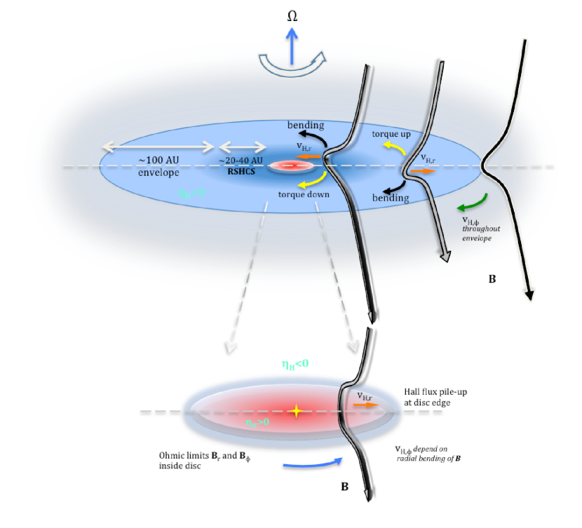
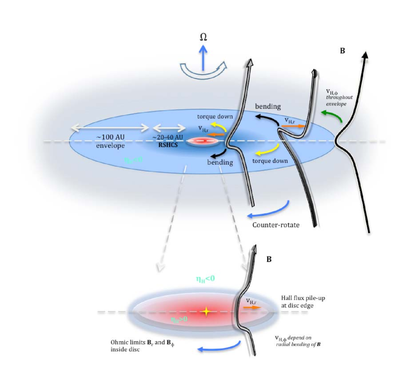
in which we neglect the contribution from the pressure term that is many orders of magnitude smaller (Zhao et al., 2018a). As a result, magnetic fields drift with velocity that is along the direction of the azimuthal current (with ). For example, in the anti-aligned configuration (Fig. 1), the magnetic field is originally bended azimuthally by the gas rotation towards in the envelope, producing a magnetic tension force along . Thus, the azimuthal Hall drift will weaken such an azimuthal bending and the corresponding magnetic braking. In situations where the Hall drift is large enough to flip the direction of the azimuthal bending of magnetic fields (“over-bending” of magnetic fields, from bending towards to ; e.g., the middle field line of the upper panel of Fig. 1), the magnetic tension force reverses direction and the magnetic braking instead becomes a magnetic spin-up of the original gas rotation along . On the other hand, if azimuthally the original field bending (gas rotation) is along the same direction as the Hall drift (towards ) such as in the aligned configuration (the middle field line of the upper panel of Fig. 2), the magnetic tension force pointing is enhanced by such a Hall drift, which can halt entirely the original gas rotation as well as further spin the gas in the opposite direction along (“over-shooting” of gas rotation: counter-rotation). Note that the azimuthal Hall drift is sensitive to the radial pinchness of magnetic field lines across the pseudo-disc, which will be weakened by the radial ambipolar drift (see Paper II for detailed discussions).
However, as toroidal magnetic fields develop in the inner envelope (102 AU scale) where rotation, either due to the original cloud rotation or the Hall spin-up, becomes much more important than infall, the toroidal magnetic fields pinched in the azimuthal direction across the pseudo-disc induces a radial current , and accordingly the radial Hall drift is:
| (8) |
(similar to Bai & Stone, 2017), in which the contribution from the magnetic pressure along the azimuthal direction is negligible. In the inner envelope (mostly ), magnetic fields drift with velocity that is along the direction of the radial current . Particularly, the radial Hall drift is always along (radially outward) if the azimuthal bending of magnetic fields goes the same direction as the above-mentioned azimuthal Hall drift (e.g., “over-bending” in the anti-aligned configuration), regardless of the polarity of the poloidal magnetic field and the sign of (squared for both and ). In this case, the radial Hall drift tends to reduce the radial pinchness of the poloidal magnetic field lines, and thus places a negative feedback to the Hall drift in the azimuthal direction.
It is worth pointing out that, the case discussed above mainly applies to collapse dominated regions where magnetic fields are primarily bended radially, so that azimuthal drift is the dominant Hall drift mode. Otherwise, in regions where magnetic fields are mostly bended azimuthally (e.g., protoplanetary discs, Bai & Stone, 2017), radial Hall drift will be the dominant mode, whereas azimuthal Hall drift becomes a secondary effect and generally (along with AD) provides negative feedback to the radial Hall drift.
2.2 Magnetic Braking Torque
Before presenting the result, we briefly investigate the magnetic torque caused by bending magnetic field lines, which will be the key to understand the magnetic braking and disc evolution. The magnetic torque for any material at a given radius is,
| (9) |
in which is the Lorentz force. Along the pseudo-disc plane, the -component of the magnetic torque that is responsible for the change of angular momentum along z-direction can be expressed, keeping only the leading terms, as,
| (10) |
In general, the second term () is much larger than the first term, since is usually the dominant component of magnetic field in our set-up. Therefore, for magnetic braking to be inefficient, both the poloidal magnetic field () and the azimuthal bending of the magnetic field () have to be small. Qualitatively, AD radially reduces the total magnetic flux arrived in the inner envelope (Zhao et al., 2018a), hence reducing therein; Hall drift mainly regulates the azimuthal bending of the magnetic field, affecting (Tsukamoto et al., 2017; Wurster et al., 2018). Usually, the radial ambipolar and azimuthal Hall drift together affects the magnetic braking efficiency. However, the radial Hall drift can dominate the radial drift of magnetic fields once the azimuthal bending of magnetic fields becomes severe. Therefore, to fully understand the behavior of magnetic field and the efficiency of magnetic braking, different components of both ambipolar and Hall drift have to be considered, which will be discussed in more details in Paper II. It is worth noting that the bending direction of magnetic field lines is not necessarily the same as the direction of drift velocities (displacement versus velocity), for both AD and Hall effect, along either radial or azimuthal direction.
From Eq. 10, we can also estimate the change of azimuthal velocity due to the magnetic force as,
| (11) |
in which the radial advection of specific angular momentum is hidden in the convective derivative. If we ignore the pressure gradient and gravitational force in the azimuthal direction, Eq. 11 shows that the time evolution of gas rotation velocity is determined by the magnetic torque (i.e., the poloidal magnetic field strength and the azimuthal bending of magnetic field lines), and that may not be directly approximated by the azimuthal Hall drift velocity (Koga et al., 2019) that mainly depends on the radial pinch of the magnetic field (Eq. 7). Instead, the radial Hall drift velocity () is a more relevant quantity, in that .
3 Initial Condition
To investigate the Hall effect in disc formation and subsequent evolution, we carry out two-dimensional (2D) numerical simulations using ZeusTW code (Krasnopolsky et al., 2010), which adopts explicit method (Sano & Stone, 2002) and sub-cycling (Huba, 2003) to treat the Hall term in the induction equation. The magnetic diffusivities are obtained by linearly interpolating the tabulated chemical network of Zhao et al. (2018b) with molecular freeze-out/desorption process turned on, which slightly enhances Hall effect at number densities between 109–1011 cm-3 than that without freeze-out (due to slightly fewer charged ions and grains; Zhao et al., 2018b).
The initial conditions are similar to the set-ups in Zhao et al. (2018a). We initialize a uniform, isolated spherical core with total mass , and radius cm AU. This corresponds to an initial mass density g cm-3 and a number density for molecular hydrogen cm-3 (assuming mean molecular weight ). The free-fall time of the core is about s yr. We adopt the same barotropic equation of state as that in Zhao et al. (2018a), with a smooth transition from isothermal to adiabatic phase to mimic the compressional heating of the gas (Tomida et al., 2013). The core is rotating initially as a solid-body with angular speed s-1 for slow rotating case, and s-1 for fast rotating case, which corresponds to a ratio of rotational to gravitational energy 0.025 and 0.1, respectively (consistent with the typical values from Goodman et al. 1993 and Caselli et al. 2002).
Because the Hall effect depends on the direction of the magnetic field, we consider both the aligned () and anti-aligned () configuration between magnetic field and angular momentum directions, which have benn shown to suppress or promote disc formation in the early phases (e.g., Tsukamoto et al., 2015b; Wurster et al., 2016). The magnetic field strength is of 42.5 G for strong field case and 21.3 G for weak field case, which gives a dimensionless mass-to-flux ratio () of 2.4 and 4.8, respectively. It is consistent with the mean value of 2 inferred in cloud cores with densities 103–104 cm-3 from the OH Zeeman observations by Troland & Crutcher (2008).
We adopt the spherical coordinate system (, , ) that better conserves angular momentum than Cartesian coordinate system in such a collapse problem. The grid is non-uniform, providing high resolution towards the innermost region of simulation domain. The inner boundary has a radius cm AU and the outer has cm. At both boundaries, we impose a standard outflow boundary conditions to allow matter to leave the computational domain. The mass accreted across the inner boundary is collected at the centre as the stellar object. We use a total of grid points. The grid is non-uniform in the -direction with near the equator, and non-uniform in the -direction with a spacing AU next to the inner boundary. The -direction spacing increases geometrically outward by a constant factor of 1.0663, and the -direction spacing increases geometrically from the equator to either pole by a constant factor of 1.0387.
The fractional abundances of charged species are precomputed and tabulated using the chemical code presented in Zhao et al. (2018b) for obtaining the magnetic diffusivities. We adopt a cosmic-ray (CR) ionization rate of s-1 (and s-1 for several comparison models) at the cloud edge with a characteristic attenuation length of 200 g cm-2 (Padovani et al., 2018, by fitting their Fig. 8). We choose mainly four different grain size distributions of MRN-type, with fixed power law index of and maximum grain size of m, but different minimum grain size =0.005 (MRN), 0.01 (min1), 0.03 (opt3), and 0.1 m (trMRN), respectively. We also consider a large singly-sized grain case with m (LG). As shown in Zhao et al. (2018b), there exists a favourable between 0.03–0.04 m for which Hall diffusivity reaches an optimal level in the inner envelope of the collapsing core; either increasing or decreasing will suppress the Hall diffusivity (either the Pederson conductivity becomes large or both the Hall and Pederson conductivity become large).
Due to the existence of short-wavelength whistler waves, explicit method for solving the Hall MHD equations can be generally unstable. Different numerical schemes have been developed to improve the stability of the Hall MHD, including higher order explicit method (e.g., Kunz & Lesur, 2013), implicit method (Falle, 2003; Tóth et al., 2008), special operator-splitting (O’Sullivan & Downes, 2007; Bai, 2014), and whistler modified Riemann solver (Tóth et al., 2008; Lesur et al., 2014; Marchand et al., 2018). The explicit method adopted in this study is second-order, the growth rate of the numerical instability can be reduced more substantially than in first-order method, as Hall time step decreases and/or with the introduction of additional physical or numerical diffusivities. Therefore, we turn on the Ohmic dissipation with a varying floor equals to the smaller of 1018 cm2 s-1 and . Such a resistivity floor is low enough to not noticeably weaken the electric current density as well as the Hall effect in the inner envelope (see discussions of Krasnopolsky et al. 2011). Furthermore, as will be discussed in § 4.2.d, the rapid increase of in the disc will significantly limit both the radial () and azimuthal () components of the magnetic field, leading to strong suppression of Hall effect in the disc. In this regard, we impose a relatively small d floor for Hall effect with d s, which caps the Hall diffusivity333The cap of is computed for each cell as CFL, where CFL is the Courant-Friedrichs-Lewy number that is set to 0.2, and is the smallest of the cell’s sizes along and directions. within 10 AU where Ohmic dissipation already dominates and in a small region of the bipolar cavity. Note that limiting actually reduces the whistler wave speed (; see Appendix B) and relaxes the requirement for small time steps to stablize the Hall MHD. Finally, we set a global ceiling of Hall diffusivity using in the Lorentz-Heaviside unit (maximum value used in Krasnopolsky et al. 2011; ), which avoids unnecessary computation cost at 103 AU scale.
With different magnetic field strength (in terms of ), grain size distribution (in terms of ), and either aligned or anti-aligned magnetic field configuration, we summarize a total of 34 numerical simulations including 2 non-rotating models, 4 slow rotating models, and 4 high models in Table 1 and 2, and 2 models with very weak magnetic field strength in Table 3. Note that 2 models (2.4trMRN-AO and 4.8trMRN-AO) from Zhao et al. (2016) considering only AD and Ohmic dissipation are also listed, to be used for analysis and comparison.
| Model‡ | Grain Size† | Radius & Morphology∗ | ||
| Dist. | (10-17 s-1) | (AU) | ||
| 2.4MRN-H-O | MRN | 1 | 0.1 | 8(FHSC)<2 |
| 2.4MRN-H+O | MRN | 1 | 0.1 | <2 |
| 2.4min1-H-O | min1 | 1 | 0.1 | 40–5016 |
| 2.4min1-H+O | min1 | 1 | 0.1 | <2 30–40↻10↻ |
| 2.4opt3-H-O | opt3 | 1 | 0.1 | 40–5016 |
| 2.4opt3-H+O | opt3 | 1 | 0.1 | <2 30–40↻10↻ |
| 2.4opt3-H-O-Slw | opt3 | 1 | 0.025 | 40–5016 |
| 2.4opt3-H+O-Slw | opt3 | 1 | 0.025 | <2 30–40↻12↻ |
| 2.4opt3-HO-NoRot | opt3 | 1 | 0 | 30–40↻16↻ |
| 2.4trMRN-AO | trMRN | 1 | 0.1 | 30–40 (Disc+Spiral/Ring) |
| 2.4trMRN-H-O | trMRN | 1 | 0.1 | 4010 |
| 2.4trMRN-H+O | trMRN | 1 | 0.1 | <2 30–40↻10↻ |
| 2.4LG-H-O | LG | 1 | 0.1 | <2 |
| 2.4LG-H+O | LG | 1 | 0.1 | 5(FHSC)<2 |
| 2.4CR10opt3-H-O | opt3 | 10 | 0.1 | 108 |
| 2.4CR10opt3-H+O | opt3 | 10 | 0.1 | <2 7↻ |
MRN: full MRN distribution with =0.005 m
min1: truncated MRN distribution with =0.01 m
opt3: truncated MRN distribution with =0.03 m,
with which Hall diffusivity reaches an optimal level in the inner envelope
trMRN: truncated MRN distribution with =0.1 m
LG: singly-sized grains with =1.0 m; note that LG models have >0 at the envelope scale, the opposite to other size distributions
H-O: Hall+Ohmic model with anti-aligned configuration ()
H+O: Hall+Ohmic model with aligned configuration ()
AO: AD+Ohmic model
Slw: model with slow initial core rotation
HO-NoRot: Hall+Ohmic model with zero initial core rotation
FHSC: first hydrostatic core
The or symbol indicates that the disc radius is growing or shrinking, repectively
The ↻ symbol indicates that the disc is counter-rotating with respect to the initial core rotation
| Model | Grain Size | Radius & Morphology | ||
| Dist. | (10-17 s-1) | (AU) | ||
| 4.8MRN-H-O | MRN | 1 | 0.1 | 7<2 |
| 4.8MRN-H+O | MRN | 1 | 0.1 | 12<2 |
| 4.8min1-H-O | min1 | 1 | 0.1 | 5015 |
| 4.8min1-H+O | min1 | 1 | 0.1 | 20<2 20↻<10↻ |
| 4.8opt3-H-O | opt3 | 1 | 0.1 | 40–5016 |
| 4.8opt3-H+O | opt3 | 1 | 0.1 | 25<2 20–30↻<10↻ |
| 4.8opt3-H-O-Slw | opt3 | 1 | 0.025 | 40–5018 |
| 4.8opt3-H+O-Slw | opt3 | 1 | 0.025 | <2 20–30↻<10↻ |
| 4.8opt3-HO-NoRot | opt3 | 1 | 0 | 40↻16↻ |
| 4.8trMRN-AO | trMRN | 1 | 0.1 | 50 (Disc+Spiral/Ring) |
| 4.8trMRN-H-O | trMRN | 1 | 0.1 | 30–40<10 |
| 4.8trMRN-H+O | trMRN | 1 | 0.1 | 20<2 20–30↻<10↻ |
| 4.8LG-H-O | LG | 1 | 0.1 | <2 |
| 4.8LG-H+O | LG | 1 | 0.1 | 10<2 |
| 4.8CR10opt3-H-O | opt3 | 10 | 0.1 | 108 |
| 4.8CR10opt3-H+O | opt3 | 10 | 0.1 | 15<2 7↻ |
| Model | Grain Size | Radius & Morphology | ||
|---|---|---|---|---|
| Dist. | (10-17 s-1) | (AU) | ||
| 9.6opt3-H-O | opt3 | 1 | 0.1 | 40–5016 |
| 9.6opt3-H+O | opt3 | 1 | 0.1 | >50 (Disc+Spiral/Ring) |
4 Simulation Results
As summarized in Table 1–2, protostellar disc formation by Hall effect alone is sensitive to microphysics, especially the grain size distribution and cosmic-ionization rate. Similar to the case of AD (Zhao et al., 2016, 2018a), disc formation is also suppressed in models with the standard MRN size distribution in which a large population of VSGs dominates the fluid conductivity and suppresses the Hall diffusivity. However, unlike the LG (single-sized 1 m grain) models in the AD result (Zhao et al., 2016), suppression of disc formation in LG models here is more severe than the MRN models, which is consistent with the values of Hall diffusivity found in Zhao et al. (2018b, see their Fig. 5).
In comparison to the existing work (Tsukamoto et al., 2015b; Wurster et al., 2016) claiming that disc formation is enabled in the anti-aligned configuration but suppressed in the aligned configuration, we instead find no such bimodality when following the disc-envelope system into the main accretion phase. In the anti-aligned configuration (<0), the initial discs (30–50 AU) formed by Hall effect have only its inner region (10–20 AU) being long-lived RSDs while the outer region being rotationally supported Hall current sheets. In the aligned configuration (>0), the initial disc suppression is followed by the formation of 20–40 AU counter-rotating discs that later evolve similarly to that in the anti-aligned case, with only the inner 10 AU RSD being long-lived.
4.1 Inefficient Hall Effect in the MRN & LG Models
 |
 |
| (a) Anti-aligned: | (b) Aligned: |
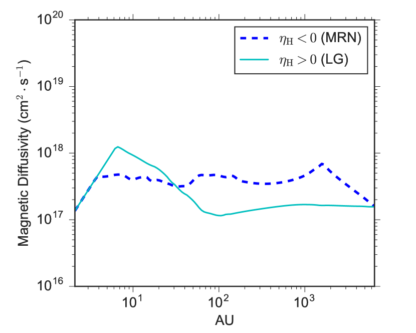
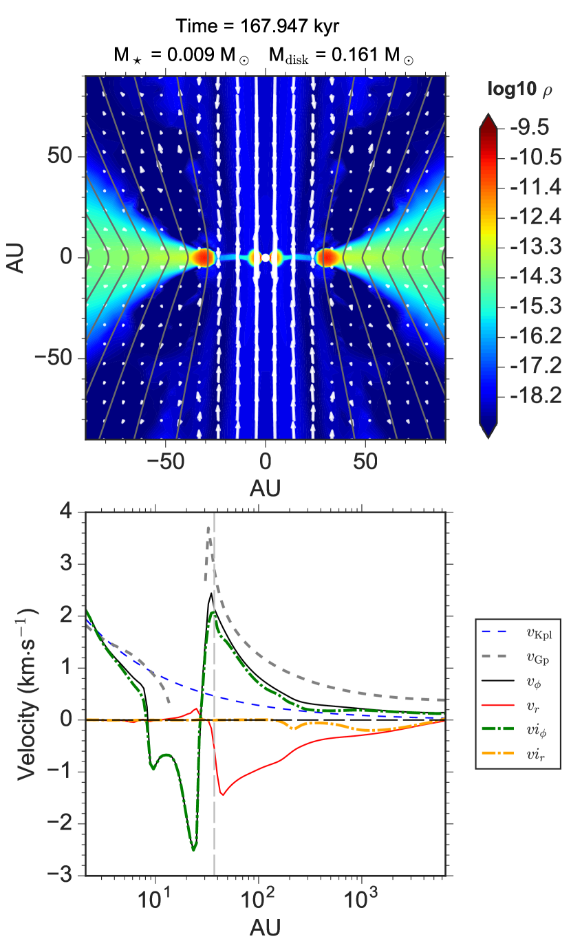
We first show that Hall effect is inefficient with either the standard MRN size distribution or singly-sized large grains (LG), which are adopted by Li et al. (2011). As shown in Fig. 3, even with an anti-aligned configuration () which has previously shown to promote disc formation, the 2.4MRN-H-O model show no rotationally supported disc larger than 2 AU (inner boundary) after the first core stage. The azimuthal Hall drift does cause the magnetic field to move somewhat slower azimuthally than the gas rotation, slightly reducing the azimuthal bending of magnetic field lines. However, such an azimuthal drift is relatively small due to the low Hall diffusivity at 10–100 AU scale (a few 1017 cm2 s-1; see Fig. 4). Thus, gas falls in with large along the pseudo-disc in the absence of sufficient rotation support, dragging the field lines inward. The radial velocity of either the charged species that dominates the Hall diffusivity () or the effective radial velocity of the magnetic field () are almost indistinguishable from the gas infall velocity , which is also a sign of insignificant azimuthal bending (towards either + or -) of magnetic fields according to Eq. 8.
In the aligned case with MRN size distribution (model 2.4MRN-H+O), disc formation is also suppressed with an even smaller gas rotation within the inner 100 AU compared to the anti-aligned case at a similar stage (in terms of total mass in the central region). As expected from Eq. 7, the azimuthal Hall drift goes along the direction of the original gas rotation (+), causing the magnetic field to surpass the azimuthal gas motion along +. At 10–100 AU scale, the enhanced field bending towards + strengthens the magnetic tension force towards - and slows down the gas rotation. On the other hand, the azimuthal field bending induces a radially-outward Hall drift of the magnetic field, which tends to curb the azimuthal Hall effect (§ 2.1). Inside 10 AU, the magnetic torque not only brakes the gas rotation, but spins the gas in the opposite direction (-) as well, creating a counter-rotating region of a few AU but with insufficient rotational velocity to form a RSD.
Similar to the MRN models, the LG models in Table 1–2 also fail to form RSDs, producing only transient first-core-like structures that last less than 1–2 kyr. Besides, such transient structures appear to be smaller in size than the MRN models, owing to a lower Hall diffusivity (1017 cm2 s-1 as shown in Fig. 4) throughout the core, especially between tens AU to 100 AU scale where Hall effect is the most relevant. Note that, unlike other cases with sub-micron grain, in the LG case (m) is positive in the density range of the dense core (104 cm-3; Zhao et al., 2018b). Therefore, the aligned configuration in the LG models is equivalent to the anti-aligned configuration in other models with sub-micron grains.
The result presented in this section is in agreement with Li et al. (2011), who find Hall effect to be inefficient in affecting disc formation, primarily due to their choice of two specific grain size distributions with relatively low Hall diffusivities. In comparison, recent work showing disc formation enabled by Hall effect (Tsukamoto et al., 2015b; Wurster et al., 2016; Tsukamoto et al., 2017; Wurster et al., 2018) mostly adopt other size distributions (e.g., 0.1 m) with enhanced Hall diffusivities. As shown in Table 1–2, a slightly truncated MRN size distribution (m) indeed facilitates the initial disc formation enabled by Hall effect.
4.2 Disc Formation & Evolution with Enhanced Hall Diffusivity: Anti-Aligned Configuration
We now present the models adopting m in which Hall diffusivity is enhanced by 1–2 orders of magnitude compared to that of MRN and LG grains, in the number density range of 109–1012 cm-3 (Zhao et al., 2018b). With such an enhanced , Hall effect strongly dominates the gas dynamics and the evolution of magnetic fields in the inner envelope. We first demonstrate the case of anti-aligned configuration (<0).
4.2.a Disc Formation and Growth at Early Times
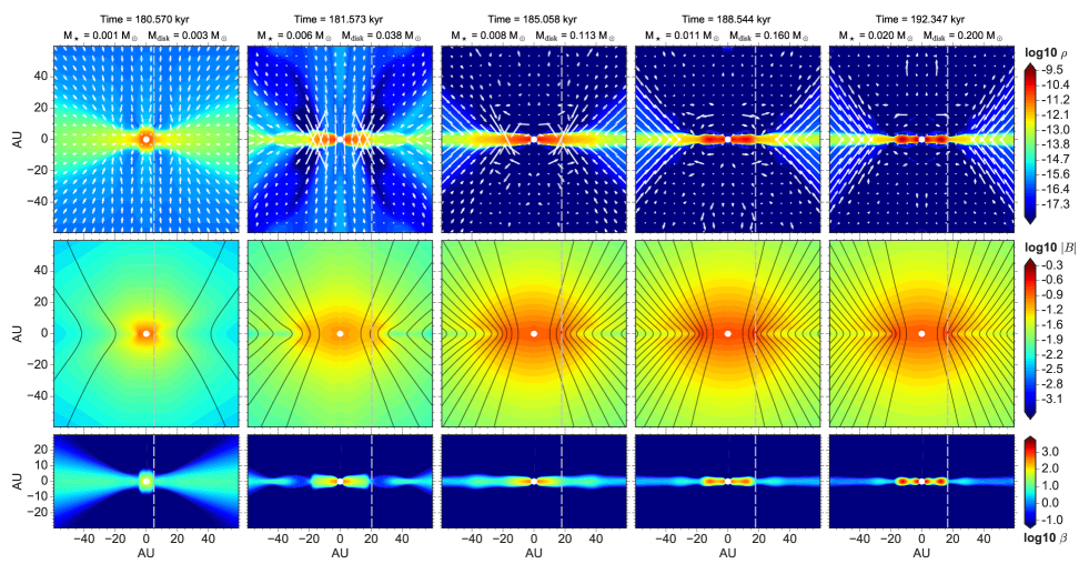
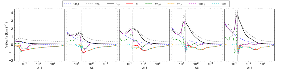
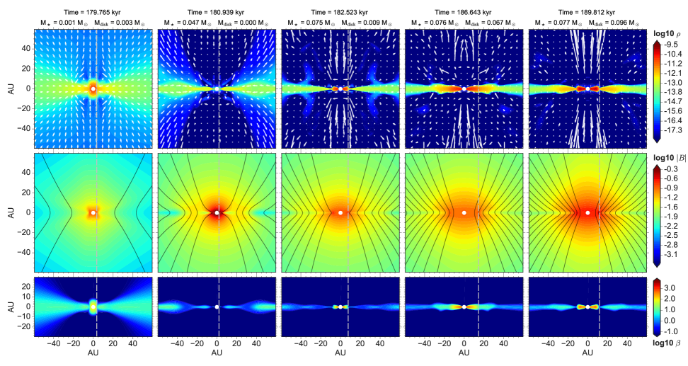
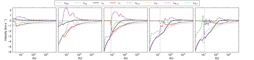
Fig 5 shows the time evolution of the inner 60 AU region of model 2.4opt3-H-O, in which an initial disc that formed after the first core stage grows within the first 4 kyr to 40–50 AU radius (similar to Tsukamoto et al., 2015b; Wurster et al., 2016). The formation of the initial disc is caused by over-bending the magnetic field lines towards - direction (the middle field line of the upper panel of Fig. 1), which generates a pure spin-up torque that accelerates the gas rotation along +-direction. For example, at kyr (Fig. 6) when the disc is in its early growth phase, the azimuthal magnetic field flips sign (bends towards -) between 20–70 AU, which naturally produces positive torques in the same region along the equator (right panel of Fig. 6). The region of field over-bending almost coincides with the region of negative in Fig. 5, also indicating that the original azimuthal field bending along + is not as severe and can be easily bent towards -. Accordingly, such a geometry also induces a large radial Hall current that drifts the magnetic field outward along the equator, with a drift velocity km s-1 (the difference between and ). Therefore, both the spin-up torque operating azimuthally and the outward drift of magnetic fields radially aid the disc formation and growth in the early phase. Note that in the inner 20 AU disc, where gas rotation becomes fast, the azimuthal magnetic field is flipped back again to +-direction and magnetic torque becomes weakly negative (at these early times).
Despite the super-Keplerian rotation speed () due to a low protostellar mass, the disc is gravitationally bound with , where
| (12) |
and is the gravitational potential (stellar potential and gas self-gravity) at distance . Fig 5 shows that the discs in the early phase after forming the first core (e.g., kyr and kyr) are rotating with a speed close to . To confirm the discs at early times are mostly rotationally supported, we examine the ratio of the dominant forces along the equator. Similar to Tsukamoto et al. (2015b) and Wurster et al. (2018), we define the ratio of the sum of the centrifugal and pressure gradient forces to the gravitational force as,
| (13) |
and the ratio of the centrifugal force to the gravitational force as,
| (14) |
The left panel of Fig. 7 shows that, at kyr when the disc radius reaches its maximum during the evolution, the inner 40–50 AU region is supported by rotation and thermal pressure against the gravitational collapse. Indeed, the sum of centrifugal and pressure gradient forces approximately balances the gravitational force (1), and the main contributor against gravity is the centrifugal support (0.8).
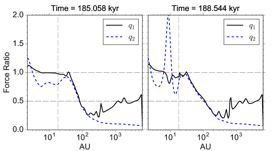
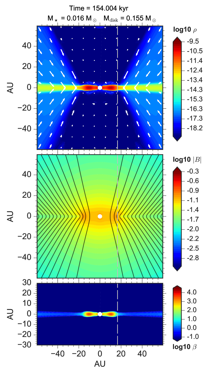
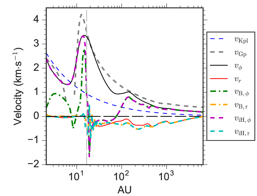
4.2.b Disc Evolution & RSHCS at Later Times
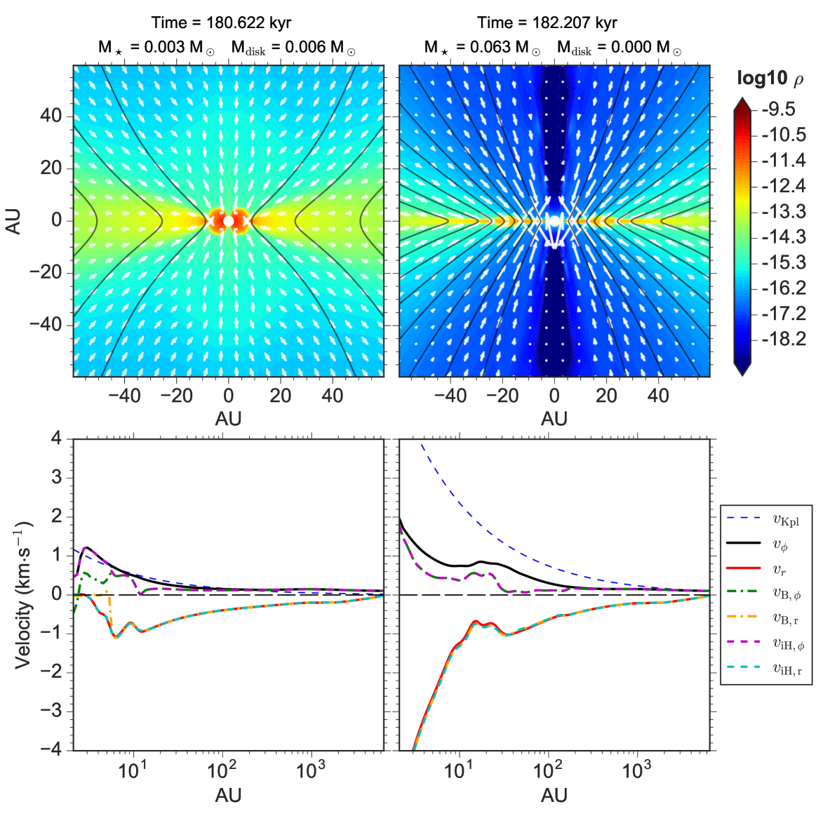
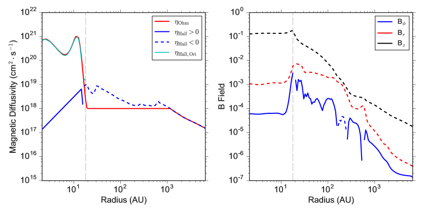
After kyr, the bulk disc gradually divides itself into two distinct partitions: (1) a long-lived inner RSD of <20 AU radius and (2) an outer Hall current sheet (between 20–40 AU) that flattens vertically over a period of 5–10 kyr. As marked in Fig. 5, we separate the two partitions by a vertical line, near which the magnetic field strength peaks and changes sign (for models with sub-micron grains). Interior to the vertical line, increases rapidly and the magnetic field strength saturates. Therefore, the vertical line approximately defines the edge of the inner RSD.
Although at later times the outer 20–40 AU partition remains rotationally supported along the radial direction (right panel of Fig. 7) due to efficient azimuthal Hall drift (fourth row of Fig. 5), it flattens vertically over time as the “fan-like” magnetic field lines remains highly pinched. In fact, despite the large rotational velocity (), the outer partition is essentially a variant of the pseudo-disc structure (Galli & Shu, 1993a, b; Allen et al., 2003a, b), with envelope gas sliding freely (2 km s-1) along the pinched field lines and flattening the outer partition. However, the highly pinched field configuration threading the outer partition is caused by the radially inward Hall drift of magnetic fields, instead of the dragging of magnetic field lines by gas infall along an usual pseudo-disc. As shown in Fig. 5, between 20–40 AU is about 0.5–1 km s-1 while gas infall speed there is nearly vanishing. Furthermore, the plasma- (, where is the thermal pressure and the magnetic pressure) in the outer partition also decreases by 1 order of magnitude from a few 101 at early times to around unity (third row in Fig. 5). To avoid confusion with usual pseudo-discs. we term such a pseudo-disc with rotational support as “rotationally supported Hall current sheet” (RSHCS).
In the RSHCS (i.e., the outer partition), though large azimuthal Hall drift efficiently weakens the azimuthal bending of magnetic field across the equator, yet the magnetic braking torque remains strong because of the accumulation of poloidal field (Eq. 10) in the RSHCS by the radially inward Hall drift. At kyr, magnetic braking torque is strongly negative (towards - in Fig. 8), with 1038 g cm2 s-1 in the inner 120 AU equatorial region (see also Fig. 9). Basically, the gas rotation that drags towards + direction becomes fast in the inner region (Fig. 5), hindering the over-bending of towards - across the equator by the azimuthal Hall drift (left panel of Fig. 8; see also the sketch in Fig. 1), even when the effective azimuthal velocity of the magnetic field (or similarly ) in some locations becomes negative, i.e., points to -. Positive magnetic torque only appears in the outer region (120–250 AU) where gas rotation along + is slow and azimuthal Hall drift towards - is sufficient to over-bend .
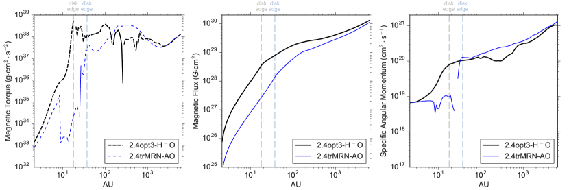
In other words, were it not for the efficient azimuthal Hall drift, the magnetic braking torque in the RSHCS would have been even stronger with the same magnitude of poloidal magnetic field ; in contrast, efficient radially outward drift of magnetic fields such as AD would easily resolve such a tension. In Fig. 9, we compare the magnetic torques of the 2.4opt3-H-O model to the 2.4trMRN-AO model, at a similar evolutionary stage. Recall from Table 1 that the 2.4opt3-H-O model is a Hall+Ohmic model with the most enhanced , whereas the 2.4trMRN-AO is an AD+Ohmic model with the most enhanced (Zhao et al., 2018b).444The AD+Ohmic model forms an axisymmetric ring of 30–40 AU (Appendix. A; see also Zhao et al., 2016) that would actually be a grand design spiral structure in 3D (Zhao et al., 2018a). The magnetic torque in the AD+Ohmic model is lower by 1 order of magnitude in the inner 100 AU region than that in the Hall+Ohmic model, which is primarily a result of the difference in the (poloidal) magnetic field strength (Fig. 5 and Fig. 17). This also implies that the efficient azimuthal Hall drift is unable to fully offset the increase of magnetic torque by a stronger . In contrast, magnetic decoupling in the AD+Ohmic model is already efficient at a broad scale (a few 100 AU to a few 1000 AU) in the envelope (Zhao et al., 2018a), which notably reduces the amount of magnetic flux dragged into the inner envelope as well as the resulting value of . In Fig. 9, the amount of magnetic flux throughout the envelope in the Hall+Ohmic model is a few times higher than in the AD+Ohmic model; the Hall+Ohmic model not only lacks an efficient mechanism to drift magnetic fields radially outward, but instead has radially inward drift of magnetic fields in the RSHCS to further increase the poloidal magnetic field and magnetic torque (see also § 5.5 for further discussions).
4.2.c Thin Counter-Rotating Shells in Anti-Aligned Models & Angular Momentum Conservation
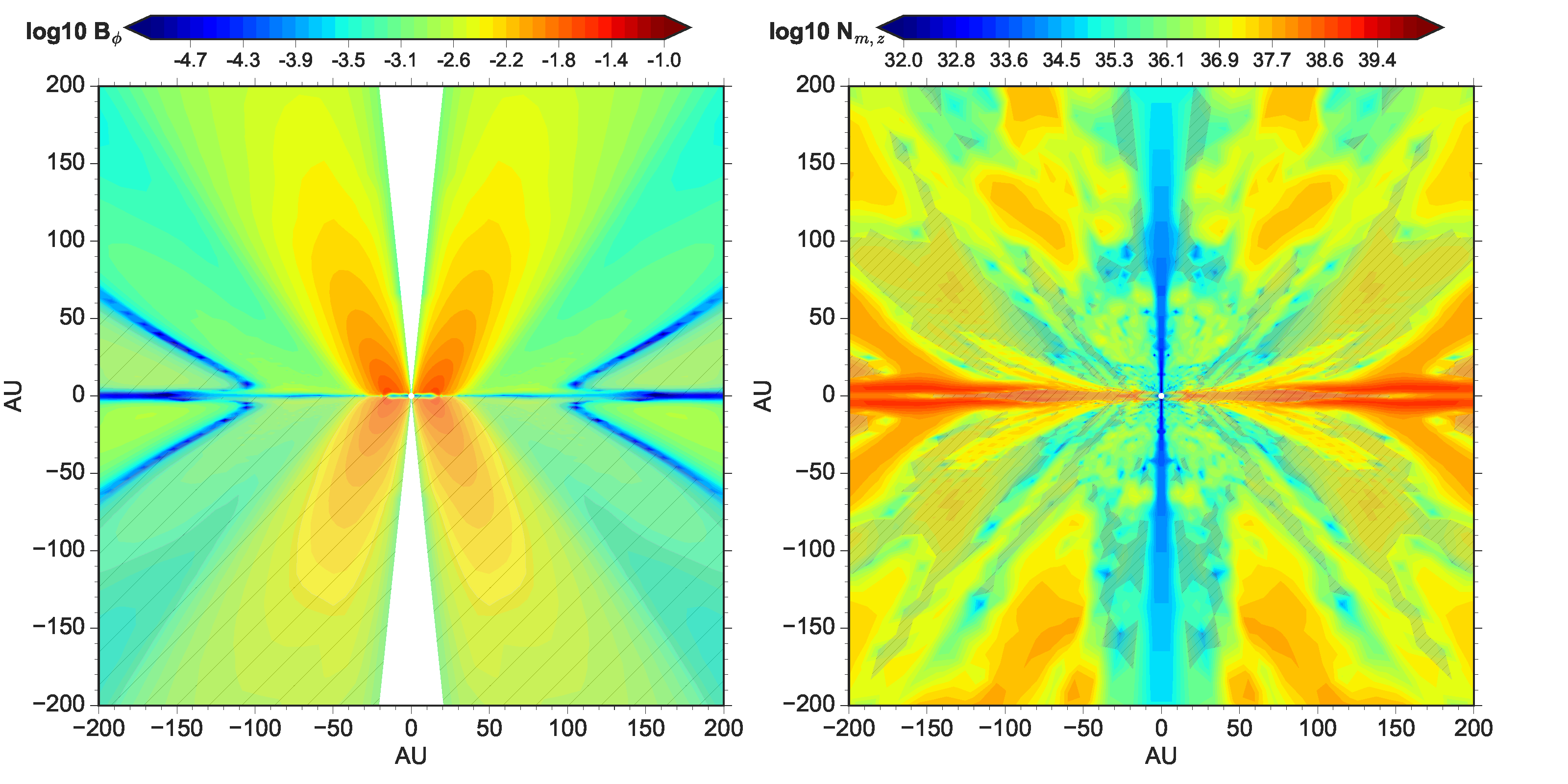
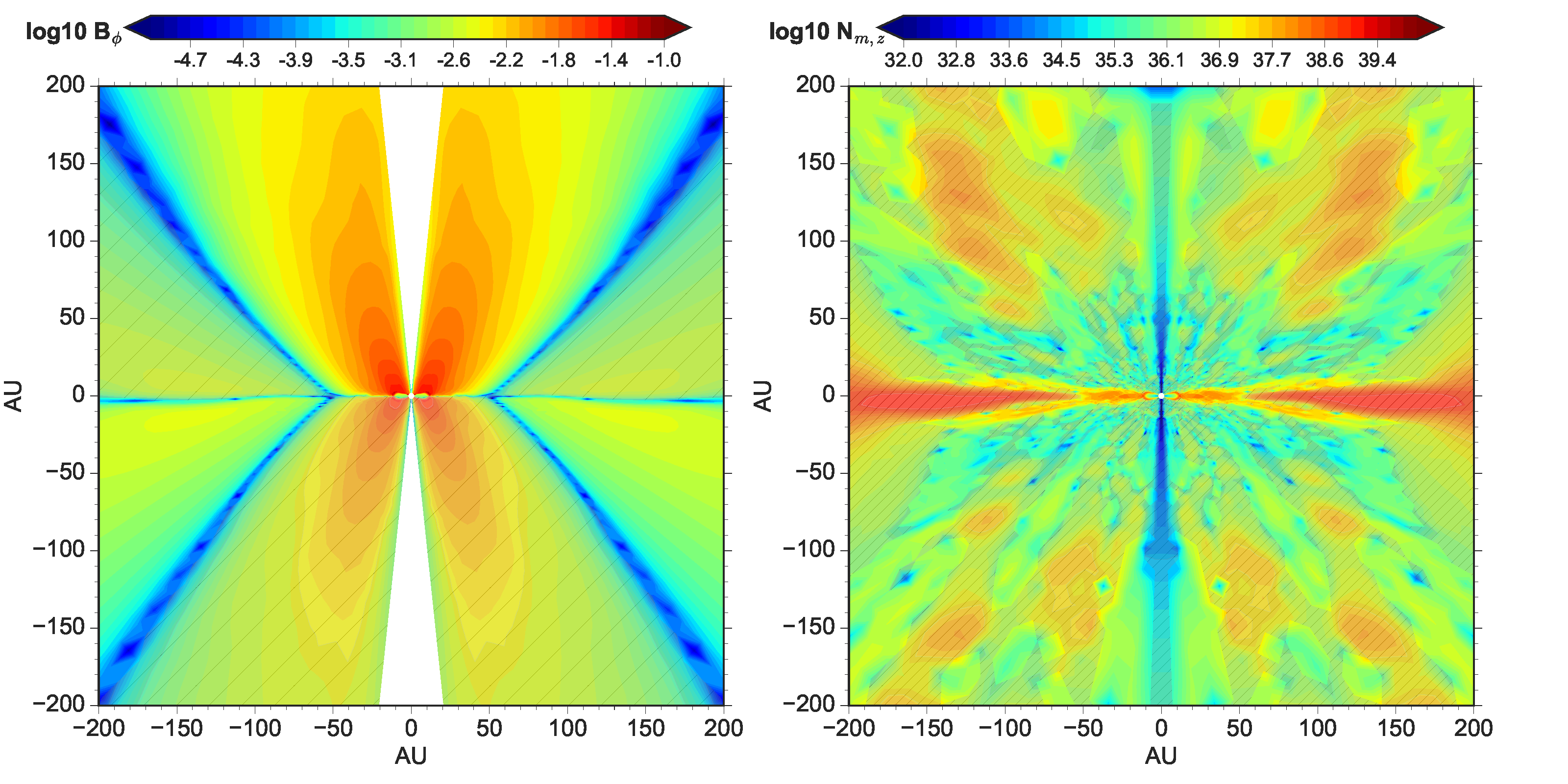
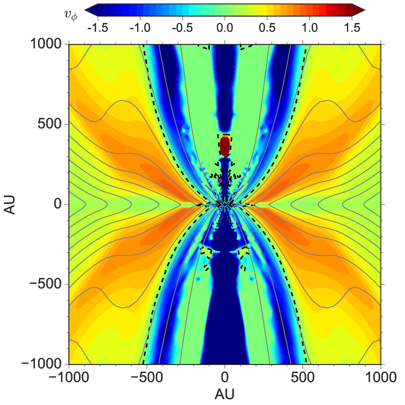
We confirm the existence of thin counter-rotating shells at 100–1000 AU scales in models of anti-aligned configuration, for example, the “butterfly-shaped” region in Fig. 10 (left panel) from model 2.4opt3-H-O (see also Krasnopolsky et al., 2011; Li et al., 2011; Tsukamoto et al., 2015b). The shell with counter-rotation () coincides with the transition region where poloidal magnetic field lines change from a convex curve (bending towards the equator) to a concave curve for the upper quadrants (or from concave to convex for the lower quadrants). The convex magnetic curves around the counter-rotating shell induce a small azimuthal Hall drift of magnetic field along + (right panel of Fig. 10), which strengthens the magnetic tension force along -, slowing down the original gas rotation and even generating counter-rotation. However, the slight increase in azimuthal bending of magnetic field lines towards + induces a secondary Hall drift along the normal vector (pointing away from the equator) of the poloidal magnetic curve that in turn reduces the curvature of the convex magnetic curve. Along the ridge of the counter-rotating shell, where the local curvature of the poloidal magnetic curve as well as the azimuthal Hall drift both approaches 0, the counter-rotating velocity reaches a maximum. The azimuthal magnetic field also flips to bend towards -, mostly following the azimuthal gas motion (). Similarly, a secondary Hall drift pointing towards the equator is induced. Therefore, the Hall drift along the normal vector of the poloidal magnetic curve and along direction feedbacks and constrains each other. The magnetic field geometry alternates along both directions and leads to the counter-rotating shells.
The counter-rotating shells contribute negative proportion to the total angular momentum budget, as shown in Fig. 9 (right panel), where a dip along the specific angular momentum distribution clearly exists between 100–1000 AU, in accordance with the scale of the counter-rotating shells. Inside 100 AU, the specific angular momentum of the Hall+Ohmic model increases again and becomes comparable to that of the AD+Ohmic model. Basically, the topology of magnetic field lines is regulated by Hall effect, extracting the angular momentum from the outer envelope and redistributing it in the inner envelope, which compensates for the strong magnetic braking near the RSHCS and sustains the inner RSD (<20 AU). Nonetheless, the total angular momentum is approximately conserved throughout the simulation, with a minor decrease by 5% over a course of 10 kyr (e.g., from g cm2 s-1 at the first core stage to g cm2 s-1 at 190 kyr for the 2.4opt3-H-O model) due to the outflow boundary condition imposed on the inner and outer boundaries of the simulation box (similar to Krasnopolsky et al., 2010). Note that the violation of angular momentum conservation found in Marchand et al. (2018) is likely originated from the numerical scheme they adopted for Hall effect, as well as from the Cartesian grid structure. Indeed, their follow-up study (Marchand et al., 2019) shows that removing the whistler wave speed in the Riemann solver for non-magnetic variables can reduce the spurious generation of angular momentum by one order of magnitude and improve the angular momentum conservation.
4.2.d Saturation of Magnetic Field Strength Inside RSD by Ohmic Dissipation
In the inner RSD, the three components of the magnetic field saturate near the mid-plane, with poloidal (0.1 G) being the dominant component and or 2–3 orders of magnitude smaller than . It is a direct outcome of the highly efficient Ohmic diffusion in the inner RSD where rises to 1020–1021 cm2 s-1 and the effective velocities of the magnetic field lines are suppressed (Fig. 5). In this regard, the d that primarily operates in the inner RSD to limit the Hall diffusivity (left panel of Fig. 11) should not affect qualitatively the behavior of the magnetic field, as the field lines inside the RSD become almost inert against any tendency of bending (bending can still be efficient near the disc surface layers and bipolar regions where is small). However, in studies fully resolving the protoplanetary disc and the magnetic diffusion, result may be different quantitatively (e.g., Bai & Stone, 2017).
Furthermore, the Hall diffusivity changes its sign to positive in the inner RSD, where only electrons are still coupled to the magnetic field and dominate the Hall conductivity (§ 2, see also Kunz & Mouschovias, 2010). As a result, such a sign change also flips the sign of Hall drift velocities in both the radial and azimuthal directions, in comparison to the drift velocities in the surrouding envelope (see Fig. 1). Recall that the radial Hall drift in the RSHCS just outside the RSD is pointing inward, the slight azimuthal bending of magnetic fields towards + (preferentially following the gas rotation) inside the RSD tends to induce a radially outward Hall drift, which may encounter those inwardly drifting field lines and produce a pile-up of magnetic flux near the disc edge. However, with the Hall d floor affecting the bulk of the inner RSD, there is only a slight indication of such opposite Hall drifts across the disc edge (see bottom panels of Fig. 5), clear identification of such a “Hall flux pile-up” may require simulations that fully resolve the Hall effect inside the RSD.
4.3 Formation & Evolution of Counter-rotating Discs with Enhanced Hall Diffusivity: Aligned Configuration
In this section, we focus on the case of aligned configuration (>0). The suppression of disc formation claimed by previous literature only holds in the first 2 kyr after the first core (Fig. 12 for model 2.4opt3-H+O), when the enhanced azimuthal bending of magnetic field towards + by the azimuthal Hall drift narrowly halts the original gas rotation (along +) in the inner envelope. As keeps bending the magnetic field towards +, magnetic tension force towards - increases and large counter-rotating motion (“over-shooting”) is able to develop from inside out. The strong spin-down torque persists and leads to the formation of a small counter-rotating Keplerian disc of a few AU at around kyr. Note that the only difference between this model and the 2.4MRN-H+O model above (Fig. 3) is the level of Hall diffusivity; in this model is larger by 1–2 orders of magnitude in the inner 100 AU (1018–1019 cm2 s-1). Hence, the effective azimuthal velocity of the magnetic field (or similarly ) and the gas counter-rotating velocity can reach as high as 2 km s-1 and -4–6 km s-1, respectively, near the central region. Up to the point of counter-rotating disc formation, the radial Hall drift of magnetic fields induced by the azimuthal bending of magnetic fields (towards +) points outward along +, i.e., the infall speed of magnetic fields is slower than that of the gas at 10–100 AU scale (bottom panels in Fig. 12). Similar to the case of anti-aligned configuration, the disc grows in radius in the next 4 kyr due to such a radially outward drift of magnetic fields in addition to the efficient spin-down torque generating counter-rotation.
As the counter-rotating motion dominates the inner tens of AU region, the azimuthal Hall drift becomes insufficient to pull the magnetic field along + (<); instead, the magnetic field starts to be dragged azimuthally along the direction of counter-rotation and even to bend towards - in the inner tens of AU (Fig. 13; see also the sketch in Fig. 2). This will cause the corresponding magnetic tension force to operate along +, which restrains and torques down the counter-rotation motion. Furthermore, the induced radial Hall drift in the inner tens of AU also reverses direction to drift the magnetic field radially inward with km s-1 (last two panels in Fig. 12). Similar to the anti-aligned case, this outer partition of the disc threaded by highly pinched magnetic fields is a RSHCS that flattens vertically over time. After the counter-rotating disc reaches a maximum radius around kyr, only the inner RSD of 10–15 AU radius is long-lived.
4.3.a Counter-rotating Inner Envelope in Aligned Configuration
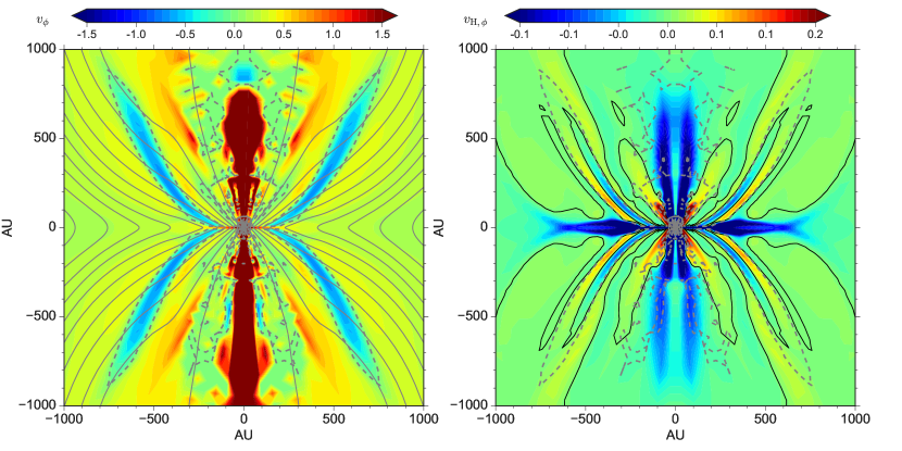
As the Hall effect is the most efficient in the inner envelope, the region with counter-rotating motion is limited to the inner 200 AU pseudo-disc plane (equator in this case) and the associated bipolar outflow cavity (Fig. 14), unlike the thin shell morphology in the anti-aligned configuration. The formation of such counter-rotating inner envelope again comes from the regulation of the topology of magnetic field lines by Hall effect; and naturally, the conservation of angular momentum is not violated. The poloidal magnetic field lines at 1000 AU scale are mostly convex (bending towards the equator) in the upper quadrants (or concave in the lower quadrants), which induces an azimuthal Hall drift along -, though small in magnitude, yet accumulatively torquing up the infalling envelope within 1000 AU to 1 km s-1 along the original direction of rotation (+).555Because the gas rotation is accelerated towards +, and the azimuthal Hall drift is relatively small ¡0.1 km s-1, the azimuthal bending of B at 1000 AU scale is following the gas rotation along +, which further increases the curvature of the poloidal magnetic field lines. Therefore, there is no obvious transition region of straightening poloidal magnetic curves from convex to concave in analogy to the anti-aligned configuration. The excess of angular momentum budget in this part of the envelope balances out the negative proportion of angular momentum (1% of the total angular momentum budget) in the inner counter-rotating part. We again confirm that the total angular momentum is mostly conserved in the aligned configuration as well, with a minor decrease by 5% over a course of 10 kyr (from g cm2 s-1 at the first core stage to g cm2 s-1 at 190 kyr for the 2.4opt3-H+O model) due to the outflow boundary conditions. The picture presented here appears to be broadly consistent with the recent observation of counter-rotation between disc and envelope around Class I protostar (Takakuwa et al., 2018).
4.4 Effect of Initial Magnetic Field Strength and Rotation Speed
Across different models we listed in Table 1–2 ( and ), the maximum radius of the disc formed via Hall effect as well as the final radius of the inner RSD are relatively insensitive to the initial magnetic field strength (for ) and rotation speed. Focusing on the models with m, the final radius of the inner RSD converges to 16–18 AU for anti-aligned configuration (<0), and 10–12 AU (counter-rotating) for aligned configuration (>0). At intermediate times, the maximum disc radius in the anti-aligned configuration is between 40–50 AU with either strong or weak field, and the maximum radius of counter-rotating disc in the aligned configuration is between 30–40 AU with strong field and 20–30 AU with weak field. Particularly, even when the initial core is not rotating, disc can still form by Hall effect with maximum and final radii between the aligned and anti-aligned limits. This convergence of disc morphology implies that the disc-envelope evolution in the main accretion phase is mostly dominated by the self-regulation process of Hall effect, which efficiently redistributes angular momentum among different parts of the collapsing envelope. As a result, one may derive analytical solutions for the equilibrium radius of the inner RSD when including only Hall effect and Ohmic dissipation (e.g., Braiding & Wardle, 2012a).
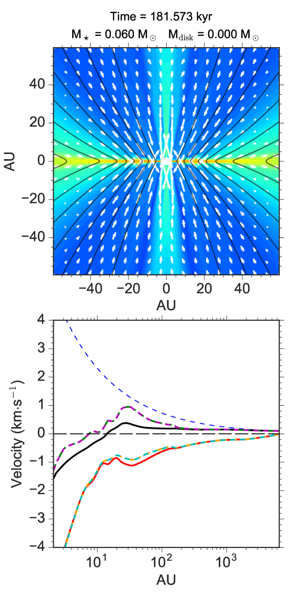
However, the outer partition of the disc, i.e., the RSHCS (between 20–40 AU; see § 4.2.b) is noticeably affected by the magnetic field strength; since the RSHCS is intrinsically a pseudo-disc structure, it becomes less prominent in the weak field models. In Fig. 15, we present the 4.8opt3-H-O model at kyr when the total mass of star and disc reaches 0.171 M☉, similar to the frame kyr of the strong field model 2.4opt3-H+O we discussed above (Fig. 5). By this time, the outer RSHCS exterior to the inner RSD (16 AU) is almost structureless and unrecognizable, except that the thin equatorial layer of the RSHCS is still rotationally supported with between 16–30 AU. The plasma- along the RSHCS is also below unity; only in the inner RSD the plasma- reaches above 103.
Note that, at early times (within a few kyr after the first core), the initial conditions do play a role in the disc morphology, especially for the aligned configuration (>0). With weaker magnetic field and/or faster rotation, a larger angular momentum reservoir in the inner envelope is able to assemble discs of 20 AU radius (e.g., model 4.8opt3-H+O and 4.8min1-H+O) that is rotating along the same direction with the initial cloud rotation. However, as the azimuthal Hall drift keeps bending the magnetic field towards + and enhancing the spin-down magnetic torque, the initial disc shrinks towards the central stellar object over time, and a new counter-rotating disc develops and grows from outside (5 AU) in the same fashion as described in § 4.3. Therefore, it is possible that in the aligned configuration, the spin direction of the star itself (and materials close to the star) can be different from the bulk protostellar disc (and winds/outflows launched from the disc) but the same as the outer cloud rotation, provided a weaker magnetic field and/or faster rotation initially as well as Hall dominating the non-ideal MHD effects.
Furthermore, we list a few other differences caused by reducing the initial cloud magnetization, which generally lowers the efficiency of Hall drift in both azimuthal and radial directions.
-
1.
The azimuthal “over-bending” of magnetic fields in the anti-aligned configuration is less prominent throughout the simulations of weak field models, hence very little outward Hall drift of magnetic fields is present.
-
2.
The counter-rotating shells in the anti-aligned configuration is slightly thicker sideways, but tightly surrounds the outflow cavity in the weak field models. The maximum counter-rotating speed reached is also somewhat smaller.
-
3.
The counter-rotating inner envelope in the aligned configuration is spatially less extended in comparison to the strong field models.
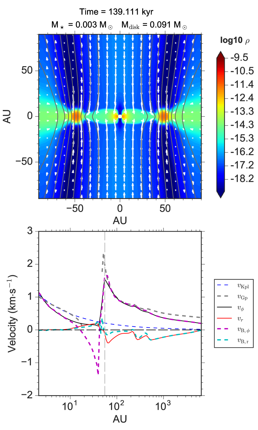
Finally, for very weak magnetic field (Table 3), we find the aligned configuration instead produce large ring structures of >50 AU that would be a grand design spiral structures in 3D. The poloidal magnetic field is only weakly pinched at 100 AU scale (small ), which leads to negligible azimuthal Hall drift of magnetic fields along + (Fig. 16). Accordingly, the tension force pointing towards - is not much enhanced by such a small to develop obvious counter-rotation. On the other hand, the magnetic field is still efficiently pulled by rotation towards +, which naturally induces a radially outward Hall drift reaching 0.3 km s-1 in the inner 100 AU. Such a radial Hall drift behaves as an equivalent ambipolar drift that diffuses magnetic flux outward; and the disc formation and evolution in model 9.6opt3-H+O is actually similar to the AD models we presented in Zhao et al. (2016, see also Appendix. A). Therefore, the formation of counter-rotating discs by Hall effect may become unlikely for very weakly magnetized cores ().
4.5 Lower Limit of Minimum Grain Size & Upper Limit of Core-Scale Cosmic-Ray Ionization Rate
As discussed in § 4.1 above, the Hall diffusivity obtained using the standard MRN size distribution is too small to generate efficient Hall drift of magnetic fields; however, as soon as the smallest grain population 100 are removed, can increase by >1 order of magnitude in the density range of 109–1012 cm-3 (Dzyurkevich et al., 2017; Zhao et al., 2018b; Koga et al., 2019). Such an enhanced is enough to form discs that are comparable to the models with optimal grain size =0.03 m. Note that when choosing =0.01 m, the values of at low densities (<109 cm-3) are still relatively low (see Zhao et al., 2018b), but it does not affect the disc formation and evolution, because Hall effect only becomes significant within 100–200 AU scale along the equatorial region. Besides, in models with =0.1 m, can briefly become positive at an intermediate scale (a few 100 AU) in the envelope (see also Dzyurkevich et al., 2017; Zhao et al., 2018b; Koga et al., 2019) but it does not seem to affect the morphology and evolution of the disc. Basically, the models with =0.01, 0.03, and 0.1 m (corresponds to min1, opt3, and trMRN in Table 1–3, respectively) are very similar in terms of disc size and morphology, indicating that Hall effect is less sensitive to grain size distribution than AD (Zhao et al., 2016), as long as the smallest grains (100 ) are absent and sub-micron sized grains are still present (instead of single sized LGs). In fact, recent observations (e.g., Tibbs et al., 2016) show evidence of depletion of nanometer grains (100 ) in dense molecular cores. Sticking of VSGs onto bigger grains has shown to be rather efficient (Ossenkopf, 1993; Hirashita, 2012; Köhler et al., 2012), which is analogous to freeze-out of larger molecules on the grain surface (Caselli et al., 1999).
We have also explored the upper limit of cosmic-ray ionization rate (at core scale), above which disc formation by Hall effect becomes inefficient. In Table 1–2, the models with s-1 (10 times the standard value) can still form rather compact RSDs of >5 AU radius that is long-lived, in either the aligned or anti-aligned configuration. In general, increasing the core-scale lowers the overall level of magnetic diffusivities. In particular, if s-1, Hall diffusivity approaches a level similar to that of MRN models with s-1. We therefore test such models with s-1 (not listed), in which small first core type of structures (<5 AU radius) quickly shrink into the inner boundary, leaving only pseudo-discs like in the MRN models. Such results remain unchanged when adopting different field strengths ( or ) and/or field orientation (aligned or anti-aligned). Note that there is little column density increase from the edge of the core to the inner envelope, and cosmic-ray attenuation only occurs at disc scale given the attenuation length of 200 g cm-2. Since the most important scale for Hall effect to enable disc formation is between a few tens AU to 100–200 AU, hence the Hall diffusivity is still conditioned by the un-attenuated at the core scale. Therefore, the upper limit of for Hall enabled disc formation should be around a few (3) times 1016 s-1. However, the upper limit could be somewhat increased if asymmetries and perturbations are present in the parent core (e.g., misalignment between the initial magnetic field and rotation axis, and turbulence close to sonic level; see Joos et al., 2012, 2013; Santos-Lima et al., 2012; Seifried et al., 2013; Li et al., 2013, 2014).
5 Discussion
5.1 Observational Evidence of Magnetic Field Polarity
A few recent observations have shown evidence of counter-rotation between disc and protostellar envelope (e.g., Harsono et al., 2014; Takakuwa et al., 2018). This type of sources may better fit with the scenario of aligned configuration between the initial magnetic field and angular momentum directions (>0). The outer envelope is rotating in the same direction as the larger scale cloud, while the inner 200 AU equatorial region and the associated bipolar outflow cavity are rotating in the opposite direction (as shown in Fig. 14). The two counter-rotating parts are distinct from each other in both space and in kinematics, and thus relatively unambiguous for observational detections. On the other hand, the counter-rotating shell in the anti-aligned configuration may be more difficult to observe, since the signal of the counter-rotating velocity from the thin shell of limited spatial extent is likely to be weak. Furthermore, such a velocity component along the line of sight at 1000 AU scale can also be confused with asymmetric infall motions (Yen et al., 2017).
5.2 Importance of Magnetic Flux Decoupling From the Collapsing Flow
One common characteristic of the discs formed in the Hall dominated cloud cores (in the absence of AD) is that, despite a brief period of growth to a maximum radius of 40–50 AU after formation, their final radius remains small (<20 AU). The outer radii of the disc evolves into a flattened pseudo-disc structure, i.e., RSHCS, with large rotation speed induced by the azimuthal Hall drift. As we have demonstrated in both the anti-aligned (§ 4.2) and aligned configuration (§ 4.3), the early growth period of the disc coincides with the period that shows prominent radially outward Hall drift of magnetic fields. Such an outward drift requires the azimuthal bending of magnetic fields to be along the same direction as the azimuthal Hall drift (e.g., over-bending of magnetic fields; see § 2.1). As gas rotation dominates the azimuthal Hall drift and is able to pull back the bending of magnetic fields azimuthally, the induced radial Hall drift then points inward, gradually dragging in more magnetic flux and causing the outer part of the disc to evolve into a RSHCS.
Therefore, in order for the RSDs to grow in radius over time, the key still lies in a persisting diffusion of magnetic flux radially outward, which is unlike to be achieved by Hall effect alone but rather relies on the ambipolar drift throughout the collapsing envelope (Zhao et al., 2018a). We will present the combined effect of Hall and AD on disc formation in Paper II.
5.3 Radius of the Inner Boundary
We also raise caution about our choice of the radius of the inner boundary , which is set to 2 AU, the same as that adopted in Zhao et al. (2016, 2018a). As demonstrated in Machida et al. (2014), a sink radius of 1–3 AU is ideal for resolving the small discs formed in collapse simulations, which can be missed if larger sink radii are used (see their Figure 1). However, they also showed that such small discs are only transient features that gradually shrink and disappear within 104 yrs; but whether a even smaller 1 AU first-core like structure can survive and persist is unclear. Zhao et al. (2018a) confirmed this type of shrinking discs and suggested that the phenomena is caused by the large amount of magnetic flux dragged into the inner disc forming region, which enhances the magnetic braking of the infalling material and reduces the specific angular momentum to be landed on the disc.
In this regard, the choice of should not affect much the models forming sizable discs of radii larger than ; even at early times, the first cores in such models (e.g., 2.4opt3-H-O) are already on the order of 5 AU. However, it is possible that in models of aligned configuration, the transient phase with the initial first core shrunk into the inner boundary (e.g., Fig. 12) may still keep a tiny disc of 2–3 AU supported by large thermal pressure, which could not be resolved in our set-up. The counter-rotating discs then gradually grow from outside the normally rotating tiny disc. Similarly, the models showing no disc formation (disc radius smaller than ; e.g., the MRN and LG models) might instead hold a tiny disc in the very center throughout the Class 0 and Class I phase. To fully resolve such tiny disc structures, a proper description of additional physical processes may be necessary, including thermal ionization, stellar X-rays, and full radiation transfer, etc., which are beyond the scope of this study.
5.4 Implications of Hall effect in Protoplanetary Disc
Although we do not elaborate in this study on the evolution of magnetic fields in protoplanetary discs (PPDs) by Hall effect, our result is closely linked to such topics. There are already a handful of studies of Hall effect in PPDs with both shearing box (Lesur et al., 2014; Bai, 2014, 2015; Simon et al., 2015) and global simulations (Bai & Stone, 2017), which show the accretion and wind launching strongly depends on the polarity of magnetic fields.
From our discussion in § 2.1, it is possible that the vertical magnetic fields threading through the PPD may only inherit one polarity (<0) from the collapse of the large scale cloud core, if Hall effect already dominates the evolution of the magnetic field in the envelope. In Fig. 1, the anti-aligned configuration results in a RSD rotating along the original cloud rotation (+) that is anti-parallel to the initial magnetic field (<0). In Fig. 2, the aligned configuration instead results in a counter-rotating disc that is also anti-parallel to the initial magnetic field (<0). Consequently, the magnetic field along the mid-plane of PPDs may preferentially drift outward (the second scenario in Fig. 1 of Bai & Stone, 2017), which further enhances the rate of magnetic flux diffusion in PPDs.
Furthermore, the negative feedback of Hall drift by its orthogonal Hall drift is rarely investigated in the literature of both disc formation and PPD evolution. In PPDs, the bending of magnetic fields by Hall drift in the radial direction should induce an azimuthal Hall drift that places a negative feedback to weaken the original toroidal bending of magnetic fields across the disc mid-plane. In Bai & Stone (2017), the straightening of the poloidal magnetic field lines is attributed to AD, whose effect may be of interest to compare with the induced azimuthal Hall drift, especially at locations where the radial bending of magnetic fields is severe (e.g., disc surface layer). Additionally, Ohmic dissipation can also be very efficient in PPD in preventing any tendency of field bending, and thus Hall effect may become less important and easily stabilized.
Nonetheless, all three non-ideal MHD effects are highly dependent on the microphysics and ionization chemistry. For example, in the vertical direction, the sign of changes from positive to negative (Fig. 1–2) across the disc surface layer (see also Xu & Bai, 2016). Hence, the same vertical field line, though bended towards opposite directions near the disc mid-plane versus the disc surface layer, may drift together towards the same radial direction, preventing the development of the so-called “Hall-shear” instability (Kunz, 2008; Bai & Stone, 2017). Such an effect from the microphysics needs to be investigated more carefully in future studies of PPDs.
5.5 Rapid Magnetic Field Oscillation & Possible Magnetic Reconnection in RSHCS
Another interesting feature of the RSHCS surrounding the inner RSD is that the radial Hall drift in this region can be fairly oscillatory and switches sign rapidly between - and +. Such a phenomenon is more pronounced at later times when a large amount of magnetic flux has been dragged into the RSHCS (see Fig. 5, Fig. 12 and Fig. 15; recall that ). The radial oscillation of implies an oscillating direction of magnetic field bending azimuthally, which is an outcome of the competition between the gas rotation and the azimuthal Hall drift . Negative (pointing inward) in the RSHCS increases the degree of radial pinching of magnetic fields and amplifies that points to the opposite direction of gas rotation in RSHCS. Once such an azimuthal Hall drift is large enough to bend the magnetic field in its direction, the induced radial Hall drift becomes positive (points outward). Positive then reduces the radial pinching of magnetic fields as well as the azimuthal Hall drift , which causes the gas rotation to dominate and to pull back the magnetic field in the direction of rotation, and restores to negative. Generally, gas rotation is large enough in the RSHCS to restrain such a brief over-bending of magnetic field in the azimuthal direction.
In essence, the oscillation of magnetic fields in the RSHCS again reveals the self-regulating nature of the Hall effect. Once the magnetic fields are bended serverely by either the radial or azimuthal Hall drift along the drift direction, a secondary Hall drift in the orthogonal direction would be induced,666Braiding & Wardle (2012a) briefly mentioned such an interdependence in their discussion section. which eventually restrains the original Hall drift. In comparison, relaxing magnetic field bending by AD is more straight-forward, in a sense that the direction of ambipolar drift is directly opposite to the bending direction of magnetic fields.
Finally, the radial oscillation of Hall drift of magnetic fields in the RSHCS can potentially promote magnetic reconnection between poloidal field lines, whose foot-points are adjacent to each other along the current sheet (pseudo-disc). There is slight evidence of such reconnection mechanisms in our simulations, in that magnetic field strength in the RSHCS does not increase drastically with time, even with being mostly negative (inward drift) in the RSHCS. This type of reconnection may be analogous to the whistler wave mediated fast reconnection often discussed in geophysics (e.g., Mandt et al., 1994; Howes, 2009). Due to the resistivity floor imposed in the RSHCS, both the oscillation of Hall drift and the magnetic reconnection could be underestimated in this study; however, including AD (to be discussed in Paper II) will suppress the formation of RSHCS along with the rapid oscillation of Hall drift.777Despite the suppression of RSHCS, the main result of the current study still holds in Paper II when all three non-ideal MHD effects are considered; i.e., there is no obvious bimodality in disc formation.
6 Summary
We have revisited the problem of disc formation by Hall effect, using 2D axisymmetric MHD simulations with magnetic diffusivities computed from our equilibrium chemical network. We have conducted a parameter study (in terms of initial magnetic field strength, rotation speed, cosmic-ray ionization rate, as well as grain size distribution), and followed the disc-envelope evolution into the main accretion phase. Our main conclusions are listed below.
-
1. In collapsing dense cores, Hall effect is inefficient in affecting disc formation if the standard MRN size distribution (=0.005 m) or singly-sized large grain (1 m) is adopted for obtaining the Hall diffusivity. The Hall drift velocity is too small to affect the azimuthal bending of magnetic fields and the resulting magnetic braking. A slightly evolved grain size distribution free of VSGs (100 ) can greatly boost the Hall effect in the inner envelope.
-
2. With an optimally enhanced Hall diffusivity corresponding to 0.03 m ( increased by 1–2 order of magnitude than that of the standard MRN in the number density range of 109–1012 cm-3), Hall effect can enable the formation of compact discs of 10–20 AU radius, regardless of the polarity of the magnetic field.
-
3. In the anti-aligned configuration (<0), initial formation of sizable discs of 30–50 AU radius is enabled by Hall effect, with only the inner 10–20 AU being long-lived RSDs and the outer region being RSHCSs that flatten over time as the Hall effect moves the poloidal magnetic field radially inward relative to matter. In the aligned configuration (>0), the initial disc suppression is followed by the formation of counter-rotating discs of 20–40 AU radius that subsequently evolve similarly to those in the anti-aligned case, with the inner 10 AU RSDs being long-lived.
-
4. The formation of thin counter-rotating shells at 100-1000 AU scales in the anti-aligned configuration is caused by the regulation of magnetic field topology by Hall effect. Across the counter-rotating shell, the poloidal magnetic curves change from convex- to concave- shaped. In the aligned configuration, however, the counter-rotating region is limited to the inner 200 AU pseudo-disc plane and the associated bipolar outflow cavity. In either configuration, the angular momentum conservation is not violated; Hall effect redistributes angular momentum among different parts of the collapsing envelope.
-
5. Disc formation via Hall effect in relatively strongly magnetized cores () is relatively insensitive to the initial magnetic field strength and rotation speed, in that the maximum radius of the disc and the final radius of the inner RSD converge to roughly similar values across different models. However, the outer RSHCS is less prominent in weaker field cases due to its pseudo-disc nature. For very weak magnetic field , the model with aligned configuration evolves similarly to an AD model, as the azimuthal Hall drift is negligible while the radial Hall drift behaves as an equivalent ambipolar drift that diffuses magnetic flux outward.
-
6. Besides removing the smallest grains (100 ) from the MRN size distribution, the cosmic-ray ionization rate at the core scale should not be larger than a few (3) times 10-16 s-1 in axisymmetric set-ups, in order for Hall effect to be efficient in disc formation in collapsing cores.
-
7. Finally, we point out that the vertical magnetic field threading through the PPD may only inherit one polarity (<0) from the Hall dominated collapsing core, in which case an enhanced rate of magnetic flux diffusion is expected in PPDs. We also discuss the rapid oscillation of Hall drift of magnetic fields in the RSHCS and possible magnetic reconnection events therein.
We conclude that disc formation enabled by Hall effect is unlikely to be bimodal. Either magnetic field polarity can result in compact RSDs of 10–20 AU radius; the main difference is the direction of disc rotation. The small disc size is closely related to the radially inward Hall drift of magnetic fields over time, and is difficult to explain recent observations of a variety of disc structures (Pérez et al., 2016; Tobin et al., 2016). Therefore, to fully solve the puzzles of disc formation, the radially outward diffusion of magnetic flux throughout the envelope remains crucial, which is to be investigated in details in Paper II.
Acknowledgements
BZ and PC acknowledge support from the European Research Council (ERC; project PALs 320620). ZYL is supported in part by NASA 80NSSC18K1095 and NSF AST-1716259 and 1815784. KHL acknowledges support from NRAO through an ALMA SOS award. HS and RK acknowledge grant support from the ASIAA and the Ministry of Science and Technology in Taiwan through MOST 105-2119-M-001-037- and 105-2119-M-001-044-MY3. ZeusTW is developed and maintained by the CHARMS group in ASIAA. Numerical simulations are carried out on the CAS group cluster at MPE.
Appendix A AD+Ohmic Model
In this appendix, we show the AD+Ohmic model 2.4trMRN-AO used to compare with the 2.4opt3-H-O model in § 4.2.b. The frame at kyr here shares a similar total mass of star and disc with the frame at of the 2.4opt3-H-O model. The axisymmetric ring of 30–40 AU (Fig. 17) would actually corresponds to a grand design spiral structure in 3D (Zhao et al., 2018a). Although AD induces negligible azimuthal drift of magnetic fields as compared to Hall effect, the radially outward ambipolar drift of magnetic fields can cause the infall speed of the magnetic field to almost vanish within the inner 1000 AU equatorial region, in this 2.4trMRN-AO model where is optimally enhanced with m. We refer readers to Zhao et al. (2018a) for more detailed discussions on the radial ambipolar drift.
Note that the criteria for identifying disc in our simulations are similar to Joos et al. (2012) and Masson et al. (2015):
-
1.
Mass density is above certain critical value g cm-3;
-
2.
Azimuthal velocity dominates over radial velocity, i.e., ;
-
3.
The material is close to hydrostatic equilibrium in the -direction, i.e., ;
-
4.
The thermal support dominates over magnetic support, i.e., .
We choose in our analysis throughout the paper.
Appendix B Constraining Hall d
In the presence of Hall effect, the Alfvén wave splits into left- and right- circularly polarized waves with different phase velocities (e.g. Wardle, 1999; Sano & Stone, 2002). The right whistler wave travels much faster than the left Alfvén wave, with a phase velocity of
| (15) |
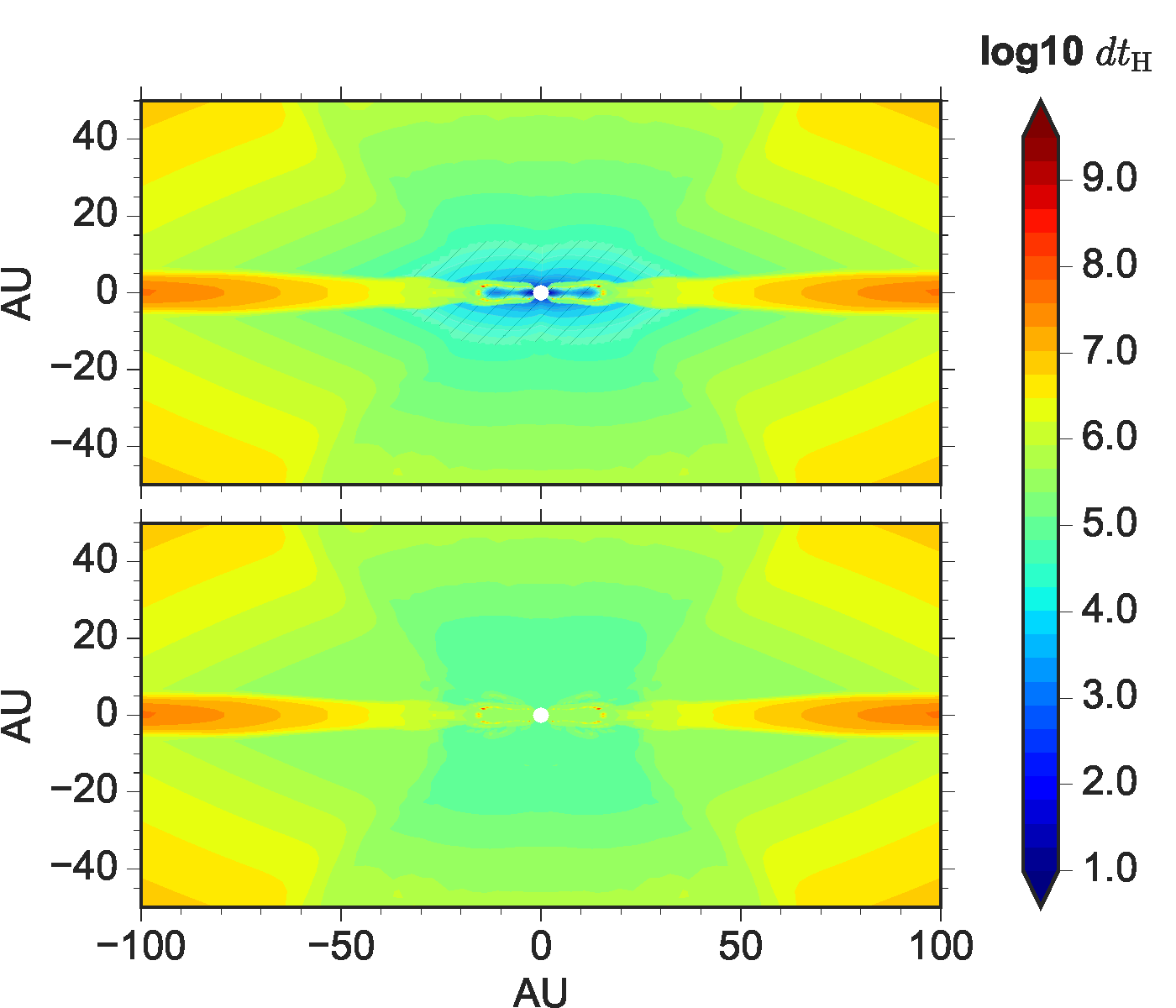
(Lesur et al., 2014; Marchand et al., 2018), where is the Alfvén speed, and is the smallest of the cell’s sizes along and directions. To resolve such a whistler wave using explicit methods, the Hall time step has to be smaller than , which can be a vanishing value and cause the growth of numerical instabilities. In this study, we relax such a time step requirement by limiting the Hall diffusivity (see footnote 3), which essentially reduces the whistler wave speed. As shown in Fig. 18, applying the technique increases the required Hall time step d from 102 s (without cap) to 104 s (with cap) in the inner RSD (dominated by Ohmic) and a small region of the bipolar cavity. Along the pseudo-disc and the RSHCS, where most of the bending of magnetic field lines and the transport of angular momentum occur, d is not affected. Therefore, the technique should have little effect on disc formation.
References
- Allen et al. (2003a) Allen, A., Shu, F. H., & Li, Z.-Y. 2003, ApJ, 599, 351
- Allen et al. (2003b) Allen, A., Li, Z.-Y., & Shu, F. H. 2003, ApJ, 599, 363
- Bai (2014) Bai, X.-N. 2014, ApJ, 791, 137
- Bai (2015) Bai, X.-N. 2015, ApJ, 798, 84
- Bai & Stone (2017) Bai, X.-N., & Stone, J. 2017, ApJ, 836, 46
- Bergin & Tafalla (2007) Bergin, E. A., & Tafalla, M. 2007, ARA&A, 45, 339
- Braiding & Wardle (2012a) Braiding, C. R., & Wardle, M. 2012, MNRAS, 422, 261
- Braiding & Wardle (2012b) Braiding, C. R., & Wardle, M. 2012, MNRAS, 427, 3188
- Caselli et al. (1998) Caselli, P., Walmsley, C. M., Terzieva, R., & Herbst, E. 1998, ApJ, 499, 234
- Caselli et al. (1999) Caselli, P., Walmsley, C. M., Tafalla, M., Dore, L., & Myers, P. C. 1999, ApJ, 523, 165
- Caselli et al. (2002) Caselli, P., Benson, P. J., Myers, P. C., & Tafalla, M. 2002, ApJ, 572, 238
- Desch & Mouschovias (2001) Desch, S. J., & Mouschovias, T. Ch. 2001, ApJ, 550, 314
- Dzyurkevich et al. (2017) Dzyurkevich, N., Commerçon, B., Lesaffre, P., & Semenov, D. 2017, A&A, 603, 105
- Falle (2003) Falle, S. A. E. G. 2003, MNRAS, 344, 1210
- Galli & Shu (1993a) Galli, D., & Shu, F. H. 1993, ApJ, 417, 220
- Galli & Shu (1993b) Galli, D., & Shu, F. H. 1993, ApJ, 417, 243
- Goodman et al. (1993) Goodman, A. A., Benson, P. J., Fuller, G. A., & Myers, P. C. 1993, ApJ, 406, 528
- Harsono et al. (2014) Harsono, D., Jørgensen, J. K., van Dishoeck, E. F., Hogerheijde, M. R., Bruderer, S., Persson, M. V., & Mottram J. C. 2014, A&A, 562, A77
- Hennebelle & Fromang (2008) Hennebelle, P., & Fromang, S. 2008, A&A, 477, 9
- Hirashita (2012) Hirashita, H. 2012, MNRAS, 422, 1263
- Howes (2009) Howes, G. G. 2009, Nonlinear Processes Geophysics, 16, 219
- Huba (2003) Huba, J. D. 2003, in Space Plasma Simulation, ed. J. Büchner, C. Dum, & M. Scholer (Lecture Notes in Physics, Vol. 615, Berlin: Springer), 166
- Joos et al. (2012) Joos, M., Hennebelle, P., & Ciardi, A. 2012, A&A, 543, 128
- Joos et al. (2013) Joos, M., Hennebelle, P., Ciardi, A., & Fromang, S. 2013, A&A, 554, 17
- Koga et al. (2019) Koga, S., Tsukamoto, Y., Okuzumi, S., & Machida, M. N. 2019, MNRAS, 484, 2119
- Köhler et al. (2012) Köhler, M., Stepnik, B., Jones, A. P., Guillet, V., Abergel, A., Ristorcelli, I., & Bernard, J.-P. 2012, A&A, 548, 61
- Krasnopolsky et al. (2010) Krasnopolsky, R., Li, Z.-Y., & Shang, H. 2010, ApJ, 716, 1541
- Krasnopolsky et al. (2011) Krasnopolsky, R., Li, Z.-Y., & Shang, H. 2011, ApJ, 733, 54
- Kunz (2008) Kunz, M. W. 2008, MNRAS, 385, 1494
- Kunz & Lesur (2013) Kunz, M. W., & Lesur, G. 2013, MNRAS, 434, 2295
- Kunz & Mouschovias (2009) Kunz, M. W., & Mouschovias, T. Ch. 2009, ApJ, 693, 1895
- Kunz & Mouschovias (2010) Kunz, M. W., & Mouschovias, T. Ch. 2010, MNRAS, 408, 322
- Larson (1969) Larson, R. B. 1969, MNRAS, 145, 271
- Lesur et al. (2014) Lesur, G., Kunz, M. W., & Fromang, S. 2014, A&A, 566, 56
- Li et al. (2011) Li, Z.-Y., Krasnopolsky, R., & Shang, H. 2011, ApJ, 738, 180
- Li et al. (2013) Li, Z.-Y., Krasnopolsky, R., & Shang, H. 2013, ApJ, 774, 82
- Li et al. (2014) Li, Z.-Y., Krasnopolsky, R., Shang, H., & Zhao, B. 2014, ApJ, 793, 130
- Machida et al. (2014) Machida, M. N., Inutsuka, S., & Matsumoto, T. 2014, MNRAS, 438, 2278
- Mandt et al. (1994) Mandt, M. E., Denton, R. E., & Drake, J. F. 1994, Geophysical Research Letters, 21, 73
- Marchand et al. (2018) Marchand, P., Commerçon, B., & Chabrier, G. 2018, A&A, 619, 37
- Marchand et al. (2019) Marchand, P., Tomida, K., Commerçon, B., & Chabrier, G. 2019, A&A, 631, 66
- Masson et al. (2015) Masson, J., Chabrier, G., Hennebelle, P., Vaytet, N., & Commerçon, B. 2015, A&A, 587, 32
- Mathis et al. (1977) Mathis, J. S., Rumpl, W., & Nordsieck, K. H. 1977, ApJ, 217, 425
- Mellon & Li (2008) Mellon, R. R., & Li, Z.-Y. 2008, ApJ, 681, 1356
- Nakano et al. (2002) Nakano, T., Nishi, R., & Umebayashi, T. 2002, ApJ, 573, 199
- Norman & Heyvaerts (1985) Norman, C., & Heyvaerts, J. 1985, A&A, 147, 247
- Ossenkopf (1993) Ossenkopf, V. 1993, A&A, 280, 617
- O’Sullivan & Downes (2007) O’Sullivan, S., & Downes, T. P. 2007, MNRAS, 376, 1648
- Padovani et al. (2018) Padovani, M., Ivlev, A. V., Galli, D., & Caselli, P. 2018, A&A, 614, 111
- Pérez et al. (2016) Pérez, L. M., Carpenter, J. M., Andrews, S. M., et al. 2016, Science, 353, 1519
- Sano & Stone (2002) Sano, T., & Stone, J. M. 2002, ApJ, 570, 314
- Santos-Lima et al. (2012) Santos-Lima, R., de Gouveia Dal Pino, E. M., & Lazarian, A. 2012, ApJ, 747, 21
- Segura-Cox et al. (2016) Segura-Cox, D. M., Harris, R. J., Tobin, J. J., Looney, L. W., Li, Z.-Y.; Chandler, C., Kratter, K., Dunham, M. M., Sadavoy, S., Perez, L., & Melis, C. 2016, ApJ, 817, 14
- Segura-Cox et al. (2018) Segura-Cox, D. M., Looney, L. W., Tobin, J. J., Li, Z.-Y., Harris, R. J., Sadavoy, S., Dunham, M. M., Chandler, C., Kratter, K., Pérez, L., Melis, C. 2018, ApJ, 866, 161
- Seifried et al. (2013) Seifried, D., Banerjee, R., Pudritz, R. E., & Klessen, R. S. 2013, MNRAS, 432, 3320
- Simon et al. (2015) Simon, J. B., Lesur, G., Kunz, M. W., & Armitage, P. J. 2015, MNRAS, 454, 1117
- Takakuwa et al. (2018) Takakuwa, S., Tsukamoto, Y., Saigo, K., & Saito, M. 2018, ApJ, 865, 51
- Tibbs et al. (2016) Tibbs, C. T., Paladini, R., Cleary, K., Muchovej, S. J. C., Scaife, A. M. M., Stevenson, M. A., Laureijs, R. J., Ysard, N., Grainge, K. J. B., Perrott, Y. C., Rumsey, C., & Villadsen, J. 2016, MNRAS, 456, 2290
- Tobin et al. (2012) Tobin, J. J., Hartmann, L., Chiang, H.-F., Wilner, D. J., Looney, L. W., Loinard, L., Calvet, N., & D’Alessio, P. 2012, Nature, 492, 83
- Tobin et al. (2013) Tobin, J. J., Hartmann, L., Chiang, H.-F., Wilner, D. J., Looney, L. W., Loinard, L., Calvet, N., & D’Alessio, P. 2013, ApJ, 771, 48
- Tobin et al. (2016) Tobin, J. J., Kratter, K. M., Persson, M. V., Looney, L. W., Dunham, M. M., Segura-Cox, D., Li, Z.-Y., Chandler, C. J., Sadavoy, S. I., Harris, R. J., Melis, C. & Pérez, L. M. 2016, Nature, 538, 483
- Tomida et al. (2013) Tomida, K., Tomisaka, K., Matsumoto, T., Hori, Y., Okuzumi, S., Machida, M. N., & Saigo, K. 2013, ApJ, 763, 6
- Tomida et al. (2015) Tomida, K., Okuzumi, S., & Machida, M. N. 2015, ApJ, 801, 117
- Troland & Crutcher (2008) Troland, T. H., & Crutcher R. M. 2008, ApJ, 680, 457
- Tóth et al. (2008) Tóth, G., Ma, Y., & Gombosi, T. I. 2008, J. Comput. Phys., 227, 6967
- Tsukamoto et al. (2015b) Tsukamoto, Y., Iwasaki, K., Okuzumi, S., Machida, M. N., & Inutsuka, S. 2015, ApJ, 810, 26
- Tsukamoto (2016) Tsukamoto, Y. 2016, PASA, 33, 10
- Tsukamoto et al. (2017) Tsukamoto, Y., Okuzumi, S., Iwasaki, K., Machida, M. N., & Inutsuka, S. 2017, PASJ, 69, 95
- Wardle & Ng (1999) Wardle, M., & Ng, C. 1999, MNRAS, 303, 239
- Wardle (1999) Wardle, M. 1999, MNRAS, 307, 849
- Wardle (2007) Wardle, M. 2007, Ap&SS, 311, 35
- Williams & Cieza (2011) Williams, J. P., & Cieza, L. A. 2011, ARA&A, 49, 67
- Wurster et al. (2016) Wurster, J., Price, D. J., & Bate, M. R. 2016, MNRAS, 457, 1037
- Wurster et al. (2018) Wurster, J., Bate, M. R., & Price, D. J. 2018, MNRAS, 480, 4434
- Wurster & Li (2018) Wurster, J., & Li, Z.-Y. 2018, Frontiers in Astronomy and Space Sciences, Vol. 5, 39
- Wurster & Bate (2019) Wurster, J., & Bate, M. R. 2019, MNRAS, 486, 2587
- Xu & Bai (2016) Xu, R., & Bai, X.-N. 2016, ApJ, 819, 68
- Yen et al. (2017) Yen, H.-W., Takakuwa, S., Chu, Y.-H., Hirano, N., Ho, P. T. P., Kanagawa, K. D., Lee, C.-F., Liu, H. B., Liu, S.-Y., Matsumoto, T.; Matsushita, S., Muto, T., Saigo, K., Tang, Y.-W., Trejo, A., & Wu, C.-J. 2017, A&A, 608, 134
- Zhao et al. (2016) Zhao, B., Caselli, P., Li, Z.-Y., Krasnopolksy, R., Shang, H., & Nakamura, F. 2016, MNRAS, 111, 22
- Zhao et al. (2018a) Zhao, B., Caselli, P., Li, Z.-Y., & Krasnopolksy, R. 2018, MNRAS, 473, 4868
- Zhao et al. (2018b) Zhao, B., Caselli, P., & Li, Z.-Y. 2018, MNRAS, 478, 2723