Not the garden hose instability: wavelength selection in a buckling garden hose
Abstract
We consider sinusoidal undulations which appear on certain garden hoses under normal use. We propose a model, using linear elasticity, explaining this phenomenon, and make a connection with biological structures as well as self-buckling. We compare observations with model predictions, and suggest potential applications in the area of shape-changing materials.
1 Introduction
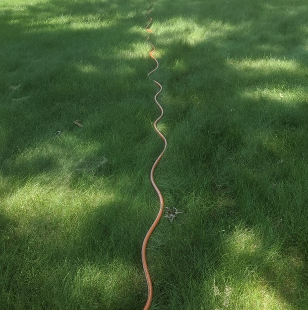
An intriguing summertime phenomenon is the sinusoidal shape sometimes assumed by certain garden hoses left on lawns. One example is shown in Fig. 1. The pattern, which can extend over the entire length of the hose, is apparently spontaneously formed during normal use. We have studied this curious phenomenon and found unexpected connections with living organisms. In this paper, we consider the underlying physics, and examine the threshold for buckling, both in the garden hose and in a biological system. We compare experimental results with model predictions for wavelength selection in the case of our garden hose instability.
2 The appearance of the deformation
Garden hoses are typically connected to a pressurized domestic water system via a shutoff valve at the inlet end, and are terminated with a spray nozzle with a control valve at the outlet end. In the normal process of watering, it is first ensured that the control valve by the nozzle is closed. Next, the inlet valve is opened; at this point, water flows into the hose, pressurizing it. The outlet valve is then opened; water flows through the hose and sprays out of the nozzle, which is directed at whatever is to be watered. When watering is completed, the outlet valve by the nozzle is typically closed first, followed by closing the inlet valve. At this point, the hose, still pressurized, is lying on the grass, often in a fairly straight line. If the outlet valve is now opened to relieve the pressure in the hose, many hoses exhibit a remarkable phenomenon: they visibly elongate as water is expelled and form sinusoidal undulations along their length. The same phenomenon occurs due to simple leakage of water from the hose. Two questions immediately arise: why does the hose elongate, and what is the mechanism of wavelength selection? We attempt to answer both questions below.
3 Garden hose architecture
A traditional material for garden hoses, still a popular option today, is rubber. Rubber garden hoses, exhibit neither the elongation nor the sinusoidal undulations described above. Elementary considerations show that the longitudinal stress in a thin-walled rubber tube of radius and wall thickness , where , under excess pressure is
| (1) |
while the azimuthal stress is
| (2) |
Remarkably, the azimuthal stress is twice the longitudinal one. The average radial stress is , which is negligible in thin-walled tubes.
To calculate the corresponding strains, we turn to Hooke’s Law in compliance form. If there are no shear stresses and the radial stress is negligible, we have [1]
| (3) |
where is Young’s modulus and is Poisson’s ratio. Substitution gives the longitudinal strain
| (4) |
and the azimuthal strain
| (5) |
For incompressible materials, . Since rubber is nearly incompressible, we find that , so that remarkably, there is no appreciable longitudinal extension of thin-walled tubes of incompressible materials when pressurized. Such behavior is desirable in blood vessels; this point is discussed in some detail for both rubber tubes and arteries in [2] and by us in Sec. 6.
A simple rubber hose thus expands or contracts in diameter when pressurized or when the pressure is removed, but remains essentially constant in length. It is then interesting to ask why certain garden hoses show a dramatically different behavior, and lengthen significantly when their internal pressure is reduced.
With advances in materials technology, a wide variety of materials are available for the construction of tubing in addition to rubber, such as polyurethane, polypropylene, polyvinyl chloride and others. More to the point, a variety of architectures are also available, and composite structures with linings and reinforcing meshes are frequently employed.
A popular current design consists of a polymer lining inside an elastomer tube, containing helically wound and nearly inextensible filaments with opposite helicity. A typical garden hose [3] with such structure is shown in Fig. 2.
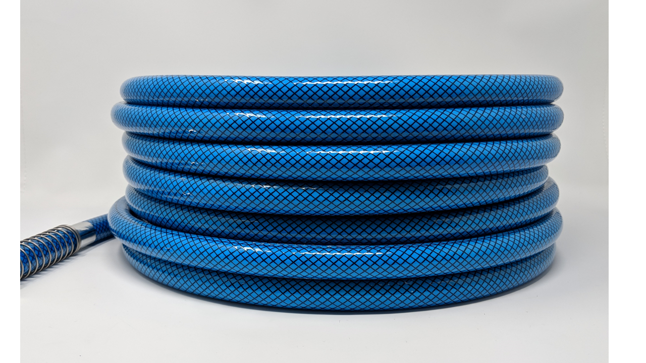
An important element in such a hose is the reinforcing helical mesh which plays a key role in the unusual behavior considered here. In all the subsequent discussions, it will be assumed that the hose maintains its circular cross-section everywhere, unless explicitly noted otherwise.
4 The helical crossed fiber array constraint
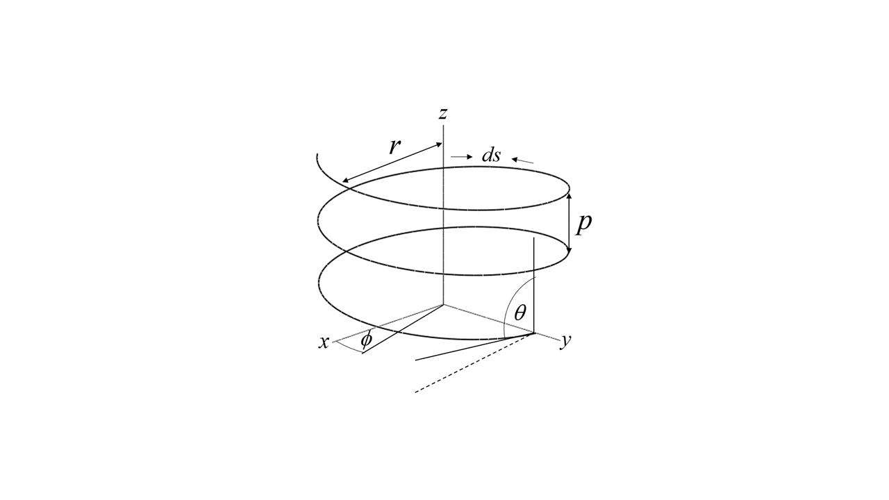
Consider a helix, winding about the -axis, as shown in Fig. 3. The position of a point on the helix, in cylindrical coordinates, is given by
| (6) |
where is the helix radius, and is related to the pitch of the helix, , via
| (7) |
The length of the helix for one period can be obtained by integrating the elemental arc length
| (8) |
and the length of the helix for one period is
| (9) |
We note that we can write
| (10) |
and
| (11) |
which defines , the helix angle, the angle that the helix makes with its axis.
We are interested in deformations of the hose allowed by the constraints due to the reinforcing helical structure. The latter consists of pairs of fibers forming helices of opposite handedness but equal pitch, as can be seen in Fig. 2. Typically, a number of such fiber pairs are present, forming a helical fiber array. This architecture resists twisting along the longitudinal center line, since such a twist would reduce the pitch for one of the helices, but increase it for the other. If there is no such twist and the fibers are inextensible, then is a constant; it is the distance along the helix for one period (where has changed by ), regardless of the pitch . Since the total number of turns traced out by either helix is a constant, is a constant of the hose. The length of the of hose is
| (12) |
and we then have that length of a fiber is
| (13) |
which links the radius and the length of the hose. This is the principle underlying the Chinese finger traps [4]; elongation causes narrowing, and vice versa.
The volume of the cavity enclosed by the hose is
| (14) |
where we have assumed, for simplicity, that the wall thickness is negligible. Eliminating using Eq. (9), we have
| (15) |
We see that changing the volume corresponds to changing the pitch and the length of the hose as well as its radius.
We note that using Eqs. (10), (12) and (15) we obtain
| (16) |
and
| (17) |
If
| (18) |
or if , then increasing the volume lengthens and narrows the hose, while if
| (19) |
then increasing the volume shortens and widens the hose. In this way, the helix angle determines whether the tube lengthens or shortens when its volume is increased. At the critical helix angle , and
| (20) |
, and the volume of the tube is maximum.
The measured helix angle of our garden hose is , placing it well into the regime where reducing the volume when the water pressure is released results in elongation. The reason for the particular choice of helix angle is not clear to us. (The manufacturer, Camco Manufacturing, did not respond to our queries.)
5 Elastic constants of the hose
The elastic modulus of the hose is of paramount importance in determining stability against buckling. We therefore consider the elastic energy cost of shape deformations associated with changing the helix angle. The structure of the hose material with the reinforcing helical filament array is clearly anisotropic, and hence a full description of the elastic properties would require at least 5 elastic constants [5]. Here we provide the simplest description consistent with the salient aspects of the elastic response.
We show that there are two distinct elastic constants in the system, and we derive expressions enabling their experimental determination.
The elastic energy density of the hose associated with the deformation can be estimated in terms of the strains as [6]
| (21) |
where is the shear modulus of the material in which the helical array is embedded. We note that this calculation is based on constant volume of the hose wall; the internal pressure is not considered.
The longitudinal strain, from Eq. (10) is
| (22) |
and the azimuthal strain along the circumference of the hose, from Eq. (11) is
| (23) |
The elastic energy density associated with deformations corresponding to changing the helix angle, from Eq. (21) is
| (24) |
Writing the energy density in terms of the strains , and , we get
| (25) |
and
| (26) |
We can then regard the effective elastic modulus associated with elongation of the hose from Eq. (25) as
| (27) |
and the effective modulus associated with a corresponding change in the radius from Eq. (26) as
| (28) |
We note that
| (29) |
Thus the elastic moduli are independent of wall thickness and radius, and and are both functions of the helix angle. The helical fiber array acts as a transformer of the shear modulus , giving rise to the two effective elastic moduli. At , , while . In the limiting case that , and , while in the limit that , and . It is important to stress, however, that thin flexible fibers can support large stresses in tension, but not in compression. Although an individual fiber would buckle readily in compression, this is not the case when the fiber embedded in an elastic host. For simplicity we neglect this contribution here, and assume for now that in compression the material behaves as if no fiber was present. Hence the expressions for the elastic constants in Eqs. (27) and (28) hold when the fibers are in tension. In compression, the behavior is essentially that of a rubber hose, and from Eq. (21) we obtain
| (30) |
If , then elongating the hose reduces its volume, while if then elongating the hose increases the volume. If the garden hose with constant volume and helix angle was under longitudinal extensional stress, the helical fibers would be in tension so long as and in compression otherwise, and if it was under longitudinal compression, the fibers would be in tension so long as , and in compression otherwise.
It is interesting to inquire about the stresses associated with the strains in Eq. (21). Here, taking derivatives of the energy density with respect to the strains to obtain the stresses is complicated by the fact that the strains not independent. We therefore take the derivatives of the energy density in Eqs. (25) and (26) and obtain
| (31) |
and
| (32) |
Taking the ratio, we find that the ratio of the stresses
| (33) |
which is at the critical angle. We remark here that is the longitudinal stress required to produce the strain , and similarly for and , not stresses arising from pressurizing the tube.
When the hose is pressurized, tension appears in the fibers. If the helix angle is not critical, the ratio of the axial force due to the tension in the fibers to the azimuthal force (easily calculated from the fiber density and orientation) differs from . This means that either the longitudinal or the azimuthal force originating from pressure is unbalanced by tension in the fibers, which leads to deformation of the hose, changing the helix angle towards the critical value. This deformation is opposed by elastic stress in the walls, but in the limit of high pressure, the helix angle reaches the critical value. This is the principle of the McKibben actuator [7] where compressed air in a helical crossed fiber array is used as artificial muscle in robotics and other applications.
The longitudinal elastic modulus of the garden hose may be determined by simply stretching the empty hose without regard to its volume. Since the stretching force is proportional to ,
| (34) |
Alternately, the longitudinal elastic modulus may be determined from the volume change of the hose due to an applied pressure . The hose volume can be written as
| (35) |
and the relative change in volume is
| (36) |
The relation between the relative volume change and the relative length change is
| (37) |
The total elastic energy of the hose is
| (38) |
The pressure , is then
| (39) |
which allows determination of the elastic constants.
6 Hydroskeletons in nature
Hydroskeletons consist of fluid-filled tubes, typically reinforced by helical filaments of opposite handedness, with a variety of helix angles. They are abundant in nature, ranging from sunflowers’ stems to tubefeet of starfishes, and shark skins [8, 9]. Their utility lies in their ability to become more or less rigid without rigid components.
If a helical fiber array-reinforced tube, with helix angle different from the critical value, is filled with water at zero excess pressure, it will be in stress-free equilibrium. If the ends are sealed, and the angle is less than critical, the tube cannot be elongated, but a compressive force on the ends can shorten the tube. Since this would increase the volume, the tube cross-section cannot remain circular, and the tube will flatten. If the angle is greater than critical, the tube cannot be shortened, but a tensile force at the ends can elongate it. Again, this increases the volume, and the tube must flatten. In either case, when the helix angle is not critical, even though the tube with circular cross-section is completely filled with an incompressible fluid, it will not be fully rigid, since it can become flattened, and bend more easily. Flatworms, for example, make use of this controllable rigidity in their locomotion [8]. However, when the angle is critical, the volume is a maximum; neither elongation nor shortening of the tube increases the volume, so the filled tube with closed ends is nearly perfectly rigid.
Until fairly recently, it was believed that all hydroskeletons in nature consisted of structures with helical fiber arrays [8]. However, in 1997, D.A. Kelly demonstrated that this is not the case. She showed that reinforcing muscle fiber arrays in hydroskeletons in the penises of armadillos were axial and orthogonal [10]; that is, either parallel to the tube axis, or perpendicular to it. (Strictly speaking, there are two helical arrays, with the limiting cases and . The corresponding elastic constants and are then infinite.) Other realizations of such fiber arrays have since been identified [9]. We return to the questions of the utility of this rare architecture in Section 10.
Before concluding this section on helical crossed-fiber arrays, we return to blood vessels: arteries. Arteries are by no means thin-walled; typically . A crude estimate of the longitudinal strain due to the systolic and diastolic pressure difference is . However, no such strain is observed. This is likely due to the structure of the artery walls: two of the three layers constituting the wall contain collagen helical filament arrays, likely near the critical angle [13].
Finally, we note that osteons, the building blocks of dense bone, have cylindrical lamellar structures with embedded crossed helical collagen fibers [14]. It appears that helical fiber arrays abound in nature; they are practically everywhere. This makes the existence of the recently discovered axial-orthogonal architecture [10] even more remarkable.
7 Buckling and wavelength selection
Ignoring the effects of gravity, if the hose is full of water, but under no excess pressure, it is undeformed, with zero stress and strain. If the hose is then pressurized, the volume of the hose increases, in our case, since , by getting wider and shorter. The hose has to undergo an elastic deformation, subject to the inextensibility constraint of the helical fibers. Elastic energy is stored in the deformed strained hose wall. If the inlet valve is next closed and the spray nozzle is opened (or the hose simply leaks at a joint), water leaves the hose, the pressure drops, and the hose elongates. The observed buckling is a direct consequence of the elongation of the hose.
To understand the proposed wavelength selection mechanism, we first imagine a straight section of the hose of length and consider its elongation assuming that the ends are free to move. Due to symmetry, the center of mass will not move during the elongation; instead the two ends will move away from the center. Since the hose is full of water, it has considerable weight, and there will be kinetic friction between the hose and the grass/earth supporting its weight. Each element of length of the hose must have a net force acting on it to overcome the kinetic friction. The longitudinal stress in the hose due to friction must therefore be a linear function of position: maximum in the middle, decreasing linearly and vanishing at the ends. If is the kinetic friction coefficient, the friction force per unit length acting on the hose is
| (42) |
where is the linear mass density and is the acceleration of gravity. The longitudinal stress in the walls of the tube at the midpoint must therefore be
| (43) |
Clearly, stress in the wall increases with distance from the end, and there must be a point where the tube becomes unstable against buckling.
If only one-half of the tube is considered, with stress linearly increasing with distance from the free end, its stress is equivalent to that in a column loaded by its own weight. The stability of such a clamped-free column has been examined by Euler [15, 16, 17]. We remark here that we have not carried out full stability analysis of the elongating garden hose, instead we rely on the analogy with self-buckling of a column. The analogy is imperfect, since the the garden hose is anisotropic due to the fiber structure, however, we believe that the mechanism for the buckling is correctly identified. We also note that the irregularities in grass density, height and ground elevation will impact on the local friction force, and introduce perturbations with consequences that are not well understood.
Remarkably, Euler erred in his first calculation 111For history see Wikipedia entry on self-buckling., but it was subsequently shown by Dinnik [18] that the column will buckle at the critical length
| (44) |
where , is the total load, is Young’s modulus and is the moment of area of the cross-section. In our example,
| (45) |
and we obtain
| (46) |
We therefore expect the wavelength of the deformation , or
| (47) |
This is our main result. Even though it is obtained via analogy and the prefactor may not be exact, we expect the scaling aspects to hold.
8 Amplitude of the sinusoidal undulation
If the buckling mechanism is as proposed above, then the amplitude of the sinusoidal deformation is simply related to the elongation of the hose; the length of the deformed hose in one period must equal the wavelength times the longitudinal stretch .
If the shape of the curve traced out by the hose is sinusoidal, that is, of the form
| (48) |
then
| (49) |
where .
For small , we have
| (50) | |||||
and the amplitude is given, approximately, by
| (51) |
9 Experimental results
The physical dimensions of the hose were determined by dissecting the hose and measuring the diameter and wall thickness. The outside diameter was found to be mm and the inside diameter mm.
The moment of area of a thin tube is
| (52) |
where is the wall thickness. In our case,
| (53) |
Key quantities determining the wavelength of the instability are the elastic modulus and the kinetic friction.
The friction force per length was measured a number of times by dragging a length of hose and measuring the required force with a spring balance. The required force can vary considerably due to different conditions of humidity, temperature and grass height, wetness and stiffness. We found
| (54) |
Another key quantity is the relevant elastic constant. In Euler’s original self-buckling calculation [17, 18], an isotropic material was considered. Our hose is anisotropic, with two different effective elastic constants. We assumed that the relevant elastic constant in our case is which relates the total elastic energy to changes in length, since both bulk compression and bend are associated primarily with longitudinal strains.
The first and most direct method to determine the longitudinal elastic constant is to stretch the empty hose by applying a force manually, and to measure the displacement of the end of the hose with a meter stick, and the force with a spring balance. We found that the displacement was proportional to the force ,
| (55) |
and for our m hose, Eq. (34) gives
| (56) |
We remark here that the force required to stretch the hose by fixed length is time-dependent: there is a relaxation time on the scale of seconds. We took force readings s after the displacement when the force reading was nearly constant.
The second and less direct method of determining the longitudinal elastic constant consisted of filling the hose with pressurized water and measuring the total volume of the water in the hose. Subtracting from this volume the volume of the empty hose gives the extra volume of the hose due to pressure . We found that from measurements on a m hose that
| (57) |
There is considerable uncertainty in these measurements due to errors associated in part with the dynamic response of the hose, and in part with accurately measuring the volume of water in the hose. The water pressure at supply was kPa, and from Eq. (40) we obtain
| (58) |
in fair agreement with the result from the stretching method. We assumed that a reasonable estimate of the effective longitudinal elastic modulus is the average of the two measurements, MPa.
Now, when a cylindrical column or hose begins to buckle, the neutral surface is along the symmetry axis of the hose, and one half of the hose is in tension, while the other is in compression. Since the helical fibers do not significantly contribute to the stress in compression, the elastic constant of the hose in the compressed half is Young’s modulus. We did not carry out elastic constant measurements under compression; however, from Eq. (30) we obtain for Young’s modulus
| (59) |
We assume that the effective elastic constant for buckling is the average of these two; that is,
| (60) | |||||
We note that longitudinal strain under pressure can be obtained from Eq. (37) to give
| (61) |
We can now calculate the wavelength of the modulation. We recall our main result, Eq. (47), duplicated here for convenience,
| (62) |
which gives the theoretical prediction
| (63) |
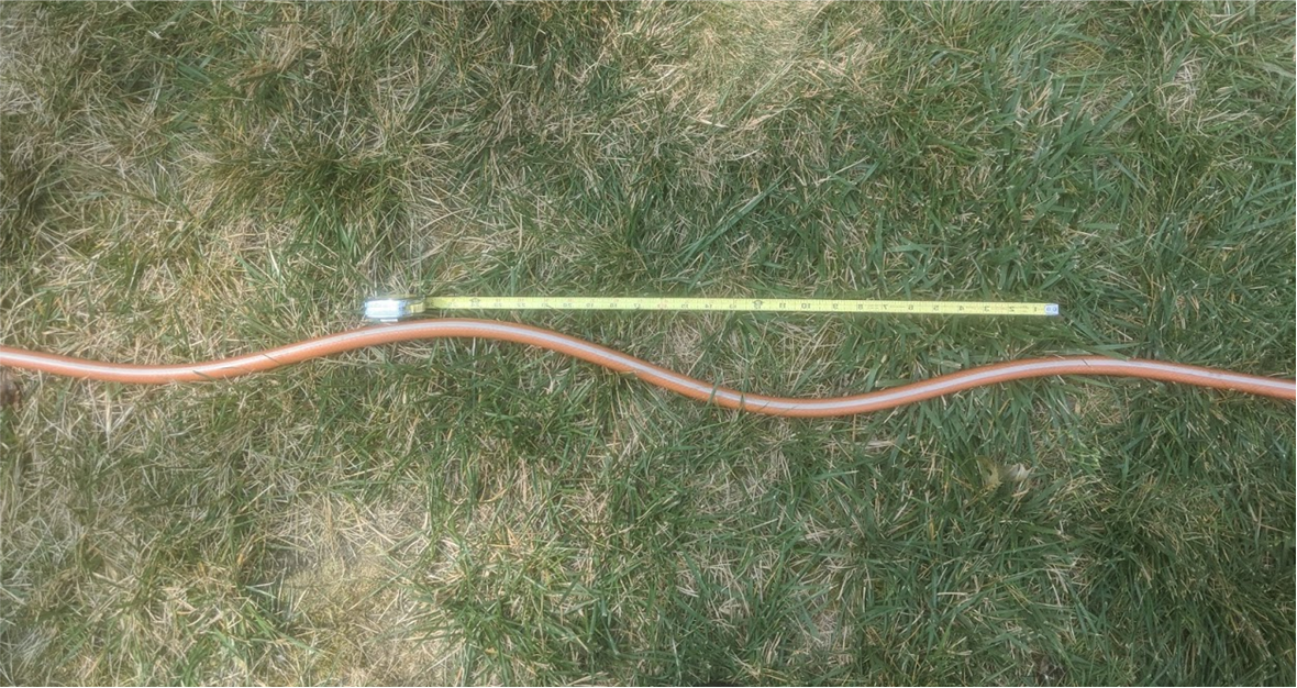
Our measured values have considerable scatter, likely due again to variations in humidity, temperature and grass conditions. The average experimental value is
| (64) |
A typical example is shown in Fig. 4.
The amplitudes of the sinusoidal undulations, which were clearly affected by surface topography, were not studied carefully. The theoretical estimate from Eq. (51) is
| (65) |
and from our observations (see Fig. 3), we estimate
| (66) |
Model predictions are therefore in good agreement with experiment.
10 A unique feature of the axial orthogonal architecture
Before concluding, we consider again the more recently discovered axial orthogonal fiber architecture [10] in the penises of mammals. In the natural world where helical fiber arrays abound, the existence of such a singular structure suggests a special and valuable property arising from it. While numerous studies [19, 20] claim that the axial orthogonal arrangement has greater resistance to bending than helical arrays, we have been unable to find measurements verifying this. There also appears to be no clear explanation of how axial orthogonal fibers create more resistance to bending than helical ones.
It is clear that ideal hydroskeletons, with inextensible fibers arranged either as helical arrays at the critical angle or axial orthogonal arrangements at maximum volume, cannot be deformed. Since deformations exist in nature, either the fibers must be extensible, or the constant maximum volume constraint must be relaxed. As in the stability analysis of our garden hose, we consider here inextensible (but not incontractable) fibers, and relax the constant volume constraint.
One biologically important characteristic of mammalian penises is stability against buckling [21, 22].
We first consider the buckling of a straight piece of garden hose of length reinforced with the helical crossed fiber array having the critical helix angle under a load . In buckling, at the critical force, the hose starts to bend. The neutral surface, whose area is unchanged as the hose starts to bend is along the axis of the hose. On one side of this surface, the hose is in tension; in the other, in compression. As in a column, the critical force for buckling is
| (67) |
where is Young’s modulus of the hose wall. (At the critical helix angle, the longitudinal elastic constant is both in tension and compression.)
To understand buckling with the axial orthogonal structure, it is useful to consider the parallels with the bending of a beam with rectangular cross section. If the beam is uniform, one surface will be stretched, the opposite surface will be compressed. The neutral surface, with an area that is unchanged as the beam is bent, is at the midplane between these two surfaces. If one now considers the same beam modified so that the previously stretched surface is now made inextensible (say by attaching inextensible axial filaments to the surface) and the beam is similarly bent, the inextensible surface will become the neutral surface. This translation of the neutral surface from the midplane to the beam surface increases the moment of area222This is similar to the change of the moment of inertia when the axis of rotation is translated. according to the parallel axis (Huygens-Steiner) theorem [23], and the bending moment needed to create the same bend will increase by a factor of for a beam with rectangular cross-section.
Returning to the hose with the circular cross-section, the critical force for buckling with the axial orthogonal fiber array is
| (68) |
Due to the inextensibility of the axial fibers, the neutral plane has moved from the center to the outside surface of the wall, the moment of area has increased by a factor of for a thin walled tube (by a factor of for a solid cylinder), and the walls are in compression with Young’s modulus . The axial orthogonal fiber arrangement thus provides a significantly increased stability against both bending and buckling due to the increased the moment of area. The effect is caused by the axial inextensibility of the outside of the wall due to the axial orthogonal arrangement; a property unique to this structure. We suppose this effect to persist, in essence, even when the hydroskeleton is full. We suggest therefore that the key property furnished by the axial orthogonal array is the approximately three-fold increase in stability against buckling; and look forward to experiments for quantitative assessment of this prediction. Later stage structural deformations beyond threshold also merit study.
11 Conclusions
We have studied the spontaneous buckling instability exhibited by certain garden hoses. We have found that the instability occurs as a result of hose elongation when water is released, and the internal pressure is reduced. The elongation is associated with the constraint on shape change associated with a helical array of fibers, with helix angles less than . During elongation, kinetic friction between the hose and the supporting surface results in stress buildup in the hose, leading to buckling. The instability is similar to the self-buckling of columns, enabling prediction of the selected wavelength. This mechanism enables simple classroom demonstrations of self-buckling using friction force as the load.
A simple model for the elastic response of the hose enabled determination of the relevant elastic modulus of the hose. This, together with the measured friction force, allowed comparison of the predicted and observed wavelengths and undulation amplitudes. We have found reasonable agreement between theory and experiment. In addition to predicting the instability and its details, our simple model provides useful insights into the effects of helical fiber arrays on the material’s response. The constraint of the array couples longitudinal and azimuthal strains, and the helix angle changes the effective longitudinal and azimuthal elastic moduli of the otherwise isotropic tube. The ability to tune elastic moduli in this way promises to be useful in the design of active shape-changing materials, such as photomechanical elastomers for a variety of applications. For example, a rubber cylinder encased in a helical crossed fiber array of photomechanical filaments would transform filament contraction to robust extension. Finally, a simple mechanism has been proposed to explain the high buckling resistance afforded by the axial orthogonal fiber arrangement in the penises of mammals.
12 Acknowledgements
We are grateful for illuminating discussions with Diane Kelly ( UMass Amherst) and Mimi A.R. Koehl (UC Berkeley). This work was supported by the Office of Naval Research [ONRN00014-18-1-2624].
References
- [1] L. D. Landau and E. M. Lifshitz. Theory of Elasticity, 3rd ed,( Pergamon Press, 1970). P21, eqn(5.14).
- [2] J.E. Gordon, Structures: or why things don’t fall down, (Penguin, 1978).
- [3] Camco Model 22783 garden hose, Camco Manufacturing
- [4] S.W. Cranford, “On Modeling Molecular Mechanisms and Mädchenfangers”, Matter 1, 788-800, October 2, 2019.
- [5] S-W Oh, T. Guo, A. Kuenstler, R. Hayward, P. Palffy-Muhoray, X. Zheng, “Measuring the five elastic constants of a nematic liquid crystal elastomer,” Liq. Cryst. DOI: 10.1080/02678292.2020.1790680 (2020).
- [6] Boyce, M.C., Arruda, E.M., “Constitutive models of rubber elasticity: A review,” Rubber Chem Technol 73(3), 504-523 (2000).
- [7] Bertand Tondu, “Modelling of the McKibben artificial muscle: A review,” Intell. Mater. Syst. Struct. 23(3) 225–253, (2012).
- [8] Steven Vogel, Life’s devices: The physical world of animals and plants, (Princeton University Press, 1988).
- [9] W.M. Kier, “The diversity of hydrostatic skeletons,” J. Exp. Biol 215, 1247-1257, (2012).
- [10] D.A. Kelly, “Axial orthogonal fiber reinforcement in the penis of the ninebanded armadillo,” J. Morph. 233, 249-255, (1997).
- [11] https://www.ted.com/talks/diane_kelly_what_we_didn_t_know_ about_penis_anatomy/transcript?language=en
- [12] S. Vogel, Comparative Biomechanics: Life’s Physical World, (Princeton University Press, 2003)
- [13] T. C. Gasser, R.W. Odgen and G.A. Holzapfel, “Hyperelastic modelling of arterial layers with distributed collagen fibre orientations,” J. R. Soc. Interface 3, 15, (2005).
- [14] M.M. Giraud-Guille, “Twisted Plywood Architecture of Collagen Fibrils in Human Compact Bone Osteons,” Calcif. Tissue Int. 42, 167 (1988).
- [15] Euler, L. “Determinatio onerum, quae columnae gestare valent,” Acta Academiae Scientiarum Petropolitanae, Vol. 1, 121-145, (1778a) (in Latin) .
- [16] Euler, L. “Examen insignis puradoxi in theoria columnarum occurentis,” Acta Academiae Scientiarum Petropolitanae, Vol. 1, 146-162, (1778b) (in Latin).
- [17] Euler, L. “De Altitudine columnarum sub proprio pondere corruentium,” Acta Academiae Scientiarum Petropolitanae, Vol. 1, 163-193, (1778c) (in Latin).
- [18] Dinnik, A.N., “Buckling under Own Weight,” Proceedings of Don Polytechnical Institute 1 (Part 2), p. 19, (1912) (in Russian).
- [19] M.A.R. Koehl, K.J. Quillan and C.A. Pell, “Mechanical consequences of fiber orientation in the walls of hydraulic skeletons,” Am. Zool. 35, 53A, (1995).
- [20] D.A. Kelly, “Turtle and mammal penis designs are anatomically convergent,”Proc. R. Soc. B, 271, 293-295, (2004).
- [21] D. Udelson, “Biomechanics of male erectile function,”J. R. Soc. Interface, 4, 1031-1047, (2007).
- [22] R.Wassersug, “Wrapping the armadillo’s penis”, Nature, 388, 826-827 (1997).
- [23] Arthur Erich Haas, Introduction to theoretical physics, (Van Nostrand, 1928).