Stimulated Smith-Purcell emission based on bound states in the continuum
Abstract
Recent advances in the development of bound states in the continuum offer new strategies to tailor electron-wave interaction and hence control the electron-induced emission. In this article we investigate the design to produce stimulated Smith-Purcell emission with a single open grating. This scheme exploits a strong radiative resonance near a bound state in the continuum, enabling staggering enhancements of multiple diffraction orders of a subwavelength grating under evanescent wave incidence. The interaction between a continuous electron beam and the radiative resonant mode bunches electrons, resulting in coherent oscillation and consequently stimulated Smith-Purcell radiation. Using a higher diffraction order for Smith-Purcell radiation, coherent radiation with low-energy electrons is also allowed. The interaction with a radiative mode that has two propagating space harmonics enables stimulated radiation towards two different directions. This work paves the way to a compact coherent radiation source, which may find application in communications, physics, and biology.
-
December 2021
Keywords: Smith-Purcell radiation, bound states in the continuum, stimulated emission
1 Introduction
In the past decade, growing interest in compact radiation sources has led to extensive analysis of various interactions between free electrons and surrounding media [1, 2, 3, 4, 5, 6, 7, 8, 9, 10, 11, 12, 13]. Among them, Smith-Purcell (SP) radiation emitted by electrons traveling over a periodic structure is an important method for realizing free-electron radiation sources [14, 15]. Ordinary SP radiation in the spontaneous emission regime has been observed from microwave to optics [16, 17]. However, such radiation is typically featured by incoherence and low power, although many mechanisms have been proposed to improve the efficiency [18, 19, 20], e.g., coupling of electrons with bound states in the continuum (BICs). Methods to improve the radiation power are of great necessity for its applications in communications, physics, and biology.
The existing approaches for coherently enhancing the SP radiation fall into two major categories: Orotrons and Smith-Purcell free-electron lasers (SP-FELs). The Orotron produces stimulated emission by utilizing the interaction between a continuous electron beam and a self-excited standing wave in an external Fabry-Perot (FP) cavity [21, 22, 23, 24]. Commercially available Orotrons can provide continuous-wave radiation with a watt level of output power at millimeter wavelengths [25]. However, the complicated cavity structure tends to hinder its wide application. The SP-FEL generates superradiant SP radiation with an open grating. It uses a surface mode bound at the grating to bunch a continuous electron beam, and the arising electron bunches generate coherent spontaneous SP radiation at the harmonics of the surface mode frequency [26, 27, 28, 29, 30, 31]. The simple structure and the described capability of frequency multiplication of SP-FELs have drawn considerable interest. However, the efficiency and radiation power of SP-FELs are limited by the spontaneous nature of the radiation [32].
In this article, we investigate the high-power stimulated SP radiation enabled by BICs. In contrast to the Orotron employing a two-mirror cavity, an open grating is employed for the electrodynamic system. Theoretical analysis of then grating upon evanescent wave incidence will be performed. Numerical investigations of the interaction between a continuous electron beam and the grating will be presented, followed by a discussion over the applicability to lower electron energies and different resonant modes. These analyses demonstrate that this method could produce coherent SP radiation efficiently, potentially enabling a compact terahertz source.
2 Model description
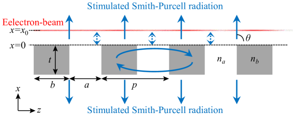
Figure 1 schematically illustrates the concept of generating stimulated SP radiation with a single open grating, which supports a strongly resonant radiative mode near a BIC. When an electron beam moves over, the radiative mode is excited by the evanescent incident field. An evanescent space harmonic of the radiative mode will in turn modulate the electron energy and intensity, leading to an enhancement of the incident field at the frequency of the radiative mode. Consequently, effective interaction between the electrons and the radiative mode takes place, resulting in coherent oscillation that transfers the electron energy to the radiative mode. The SP radiation, corresponding to those propagating space harmonics of the radiative mode, can be significantly enhanced due to the beam-wave interaction.
The associated mechanism is described in detail as follows. For simplicity, an infinite extent in the direction of the structure depicted in figure 1 is assumed. The dielectric grating comprises of alternating high-index () and low-index () bars of thickness . is located at the top of the grating. The electron beam can be treated as a number of line charges moving in close proximity to the grating at with a charge density distribution per unit length in the direction and an initial velocity of in the direction, with being the speed of light. The current density in the time domain can be written as [30, 33, 18]
| (1) |
where is the total number of line charges, is the position of the th line charge at . The current density in the frequency domain is then obtained via Fourier transform, as
| (2) |
where and [30]. Between the beam and grating, the fields induced by the current can be characterized by its magnetic field:
| (3) |
where is the wavenumber, the free-space wavenumber [33, 18]. With , is imaginary, and the field described by (3) is nonradiative.
Upon evanescent wave incidence, the periodic nature of the grating suggests that the reflected and transmitted waves can be expanded into a series of space harmonics. Considering the ordinary SP radiation in the spontaneous emission regime, where the beam-wave interaction can be neglected, the fields of the th diffraction order above the grating can be given by
| (4) | |||
| (5) |
where , , and are the reflection coefficient, wavenumber and wavenumber of the th diffraction order, respectively [30, 33, 18].
The eigenmodes of the grating play an essential role in determining the diffraction properties. All the space harmonics are evanescent for a surface eigenmode, while one or more propagating space harmonics emerge for a radiative eigenmode. The SP emission requires the excitation of radiative modes. In this case, rewriting the wavenumber in terms of the radiation angle for those propagating space harmonics, , one obtains the well-known relation between the radiation wavelength and the electron velocity
| (6) |
To produce SP radiation efficiently, a considerable deal of work has been devoted to studying the evanescent-to-radiative wave conversion efficiency [34, 35, 36, 18, 20], while the coexisting evanescent space harmonics of a radiative mode have seldom been utilized. In contrast, we will show that, by exploiting a resonant radiative mode near a BIC, the 0th-order space harmonic can bunch electrons and enable stimulated SP radiation. Apperently, the 0th-order space harmonic is phase synchronous with the electrons. The energy gain of a phase-matched electron from the longitudinal electric field over one grating period is
| (7) |
where is the elementary charge, is the start phase of an electron. Electrons with lose energy, and electrons with gain energy. Such dependence leads to electron energy modulation, which bunches the electrons at the frequency of the radiative mode. For periodically bunched beams, the incident fields induced by the electrons concentrate in the bunching frequency and its higher harmonics, thereby leading to coherent oscillation that transfers energy from the beam to the radiative mode [27]. Note that all those space harmonics of a single eigenmode operate at the same frequency and are not independent [37]. Owing to the energy transfer, the amplitudes of all those space harmonics will be scaled by a common factor and the SP radiation included in them is generated by stimulated emission.
Notice that this scheme is different from the Orotron and SP-FEL. For the Orotron (e.g., as presented in [38]), the stimulated nature of the radiation from the standing wave in the cavity that directly interacts with the the electron beam is similar to this scheme. However, the structure and FP resonance mechanism of the Orotron cavity formed by two mirrors, with a grating embeded in one of them, are different from the single grating structure and BIC resonance mechanism used in this scheme. For the SP-FEL (e.g., as presented in [28]), the single grating structure used for beam-wave interaction is similar to this scheme. However, effective beam-wave interaction in the SP-FEL takes place between the electron beam and a surface mode of the grating that has no propagating space harmonic. Thus, the electron beam is bunched at the frequency of the surface mode but no SP radiation at such frequency can be enhanced. In the absence of direct interaction with the electron beam, the fields of radiative modes at the harmonics of the bunching frequency are enhanced by superradiant effect, which produces spontaneous radiation but not the stimulated radiation in this scheme [27].
3 Physics of BIC resonances
The diffraction characteristics play an essential role in the proposed scheme. Concerning a constant excitation stimulated by a continuous electron beam, high reflection coefficients of the 0th order and the propagating orders are needed for effective beam-wave interaction and efficient far-field radiation, respectively. We will show that, making use of a strong resonance near a BIC, those space harmonics can be greatly enhanced at the resonant frequency. To this end, we use the waveguide-array (WGA) modes formulation, which was initially introduced to explain the reflection of a plane wave impinging on a grating [39]. Such mode-matching method not only provides a straightforward routine to extract the reflection coefficients of a grating but also leads to intuitive physical insights into its extraordinary properties [40, 41, 42, 43]. Below we generalize the analytical method and derive the WGA modes in gratings under evanescent wave incidence.
Along the direction, the grating can be treated as a periodic array of waveguides, where a series of WGA modes exist. Concerning a TM-polarized incident wave, these WGA modes can be denoted as , , , etc. The lateral magnetic field profile in the direction for the mode can then be expressed as
| (8) | |||||
| (9) |
where the wavenumbers in the low-index bar and high-index bar are and , respectively, and is the wavenumber. Enforcing the continuity of tangential field components at the bar interfaces and the Bloch boundary condition yields the dispersion relation for WGA modes,
| (10) |
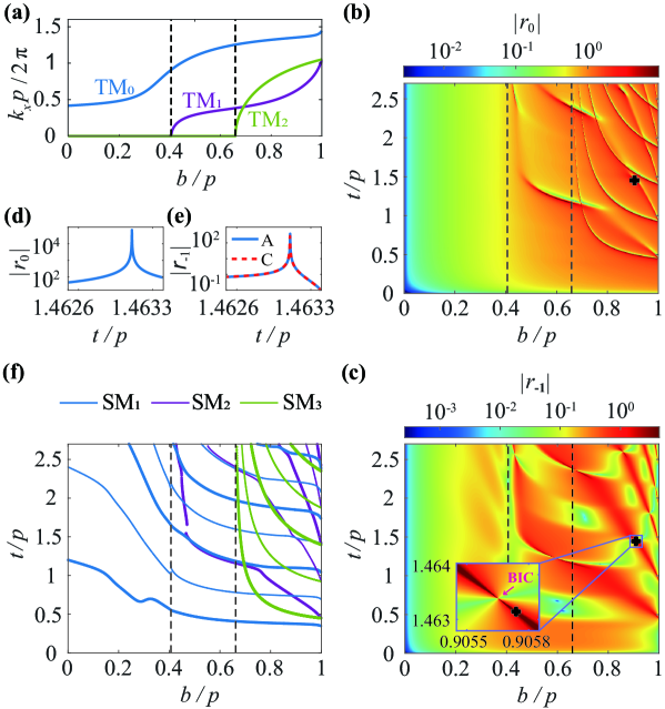
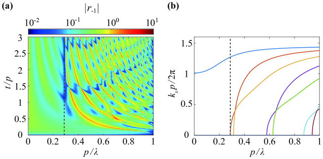
Equation (10) suggests the plausible control of the number of WGA modes by adjusting the dutycycle for given values of beam energy, grating period and wavelength. For instance, with , (), , and , we show the dependence of on the dutycycle in figure 2(a). As dutycycle increases, more and more modes exist.
The introduction of grating boundaries in the direction confines the WGA modes inside the grating by coupling to the outside space harmonics. Following the analytical mode-matching method proposed in [39], the reflection coefficients and can be determined, as shown in figures 2(b)–2(e). Figure 2(e) compares the values of using the WGA analytical solution and COMSOL [44], where a satisfactory agreement is obtained. A BIC can be considered as a resonance with zero leakage and zero linewidth [45]. Figures 2(b)–2(e) reveals that, BICs can be excited for appropriate dutycycles and thicknesses. A small variation of the parameters from the BIC leads to a strong radiative resonance such as the operation point [18], where both and are greatly enhanced.
The highly-ordered patterns in figures 2(b) and 2(c) reveal an interference effect. We will show that this phenomenon, as well as the origin of BIC resonances, are linked with the FP-resonance mechanism of those WGA modes. Inside the grating, the magnetic field including a number of WGA modes propagating downward can be given by
| (11) |
where is a diagonal propagation matrix composed of , and is a state vector[42]. After a round trip in the grating, the state vector becomes , where is the propagation matrix, and the reflection matrix at the interfaces. The original obtained by the mode‐matching method is undiagonal, i.e., WGA modes are not orthogonal. The diagonalization of the matrix provides a new set of orthogonal modes, namely “supermodes” [39]. Accordingly, the phase shift accumulated by the th-order supermode () after a round trip corresponds to the phase of the th eigenvalue of , denoted by . FP resonances occur when the round-trip phase shift is , where is an integer.
Figure 2(f) shows the combinations of thickness and ducycycle supporting the FP resonances. The patterns in the and maps are grided by different resonance curves, which indicates different contributions to the space harmonics from each supermode. A strong BIC resonance can be obtained when and reach their conditions in phase, with , being an even integer. We will show that stimulated SP radiation can be eventually enabled in the presence of the interaction between an electron beam and the BIC resonance.
Note that the supermode being self-sustainable requires [39]. For a nontrivial solution to exist, the determinant of the coefficients should be zero, yielding the dispersion relation:
| (12) |
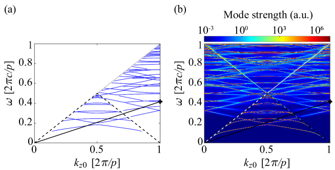
where is an identity matrix. The combinations of and corresponding to the minima of being less than 0.5 are shown in figure 3(a) for a grating with and , which are the same as the operation point in figure 2. Here, only the reflection coefficients below the light line () are calculated, because the excitation is stimulated by an evanescent incident wave. Figure 3(b) shows a full dispersion diagram obtained by Lumerical FDTD simulation with Bloch boundary conditions on a single grating period. Good agreement between the analytical solutions and the FDTD simulation results below the light line indicates the correctness of the dispersion relation given by equation (12).
Interestingly, the analytical method introduced here is readily to be used for the inverse SP effect. Dielectric laser accelerators based on such effect have shown great potentials in recently years [46]. Upon the incidence of a laser on the grating, one synchronous evanescent space harmonic generated by the diffraction effect can efficiently accelerate electrons [47]. Compared to the SP effect with evanescent wave incidence, the analysis for the inverse SP effect with propagating wave incidence follows roughly the same steps, except that the expression in (3) should be modified to match the incident laser field. The accelerating gradient depends on the calculated reflection or transmission coefficients for the synchronous space harmonic, which may also be enhanced by the BIC resonances. If the laser wavelength, incident angle and electron energy of the inverse SP effect agree with the radiation wavelength, radiation angle and electron energy of the SP effect, the required grating parameters to enable BICs should be the same.
4 Beam-wave interaction
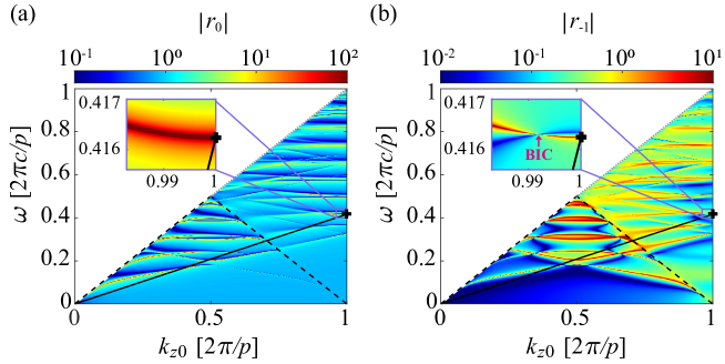
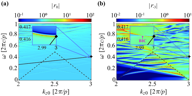
Firstly, we consider the interaction between a 51 keV electron beam and a grating by following the parameters of the operation point in figure 2. To study the beam-wave interaction, the reflection coefficient and for a grating with and are also calculated by the WGA analytical solution versus angular frequency and , as shown in figure 4. These diagrams show the same dispersion curves as in figure 3, with different dispersion curves illustrated by extraordinarily high reflection coefficients [42]. The operation point marked by the black star, which is also shown in figure 3, is the intersection of the 51 keV beam line with one dispersion curve. The operation point is located above the region of surface modes, corresponding to a radiative mode with the -1st-order space harmonic being the SP radiation. A strong resonance is induced at the operation point by a nearby BIC for effective beam-wave interaction, as depicted in the insets of figure 4(b).
Now we show that the beam-wave interaction enables electron bunching and thus stimulated SP radiation through two-dimensional simulations with a finite-difference-time-domain-based fully electromagnetic code CHIPIC [48, 49, 50, 51]. While our theory is general, we choose an operation frequency of 0.2 THz to exemplify our concept. Grating and electron parameters are determined by the operation point in figure 4. A grating with dutycycle , thickness , period and number of periods is used. On top of the grating, a sheet electron beam of energy , thickness , and current density are placed in an external uniform longitudinal magnetic field of 0.7 . Considering the small transverse extent of the 0th-order space harmonic, the spacing between the beam and grating is set to be 50 . We note that such a single-layer grating could be realized exploiting lithographic and etching techniques [52], and the required electron density can be achieved with state-of-the-art emitters [53].
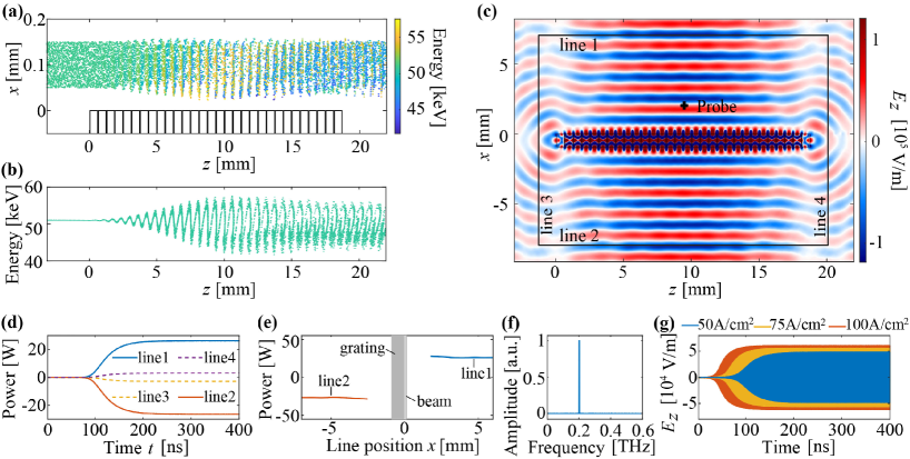
Figures 5(a) and 5(b) show the particle and phase-space distributions of the electron beam, respectively. Along the longitudinal direction, the electrons interact with the self-excited resonant radiative mode, inducing an energy modulation. After a distance, faster electrons intersect slower ones, so the energy modulation develops into density modulation. Owing to the periodicity of the 0th-order space harmonic along the direction (), electron bunches are separated by one grating period. Due to the evanescent nature of the 0th-order space harmonic, electrons closer to the grating experience stronger energy modulation and therefore form bunches earlier. On the right side of figure 5(b), there is a significant decrease in the overall electron energy, resulting from the beam-to-wave energy conversion.
Figures 5(c) shows the field pattern, indicating that the SP radiation is indeed propagating in the normal direction (). It should be noted that the finite grating length in the direction leads to omnidirectional radiation at both ends. To evaluate the efficiency, the radiation powers towards different directions are detected by four lines shown in figure 5(c). Assuming a grating width of 1 mm, figure 5(d) indicates that, the maximum total power of the SP radiation propagating in the normal direction (the sum of the powers through line 1 and line 2) is about 52.8 W, and the maximum total power of the radiation towards other directions (the sum of the powers through line 3 and line 4) is about 5.9 W. In comparison, the power in the normal direction is much higher than the power towards other directions. The corresponding power conversion efficiency for the SP radiation through line 1 and line 2 is about 2.1%. In figure 5(e), by changing the positions of line 1 and line 2, we found that the radiation power keeps almost constant in the normal direction, indicating the SP radiation is fairly directional. Figure 5(f) shows that the radiation frequency detected by the probe marked by a black star in figure 5(c) is about 0.2 THz, consistent with the prediction by (6). Figure 5(g) shows the fields detected by the probe for different current densities, indicating that the radiation can be potentially enhanced by increasing the electron beam current.
Secondly, we consider the interaction with a smaller electron energy, which would be desirable for a compact and cost-effective free-electron radiation source. When the operation frequency and radiation angle are held constant, it is possible to use a smaller electron energy by reducing the grating period, as shown in figure 6(a). For example, with grating period , the required electron energy to radiate the -1st-order space harmonic at is reduced to 30 keV. However, as shown in figure 6(b), there is an inferior limit for the electron’s normalized velocity to support at least two WGA modes propagating inside the grating, which is required to enable BICs. To solve this problem, we can use higher-order space harmonics as SP radiation.
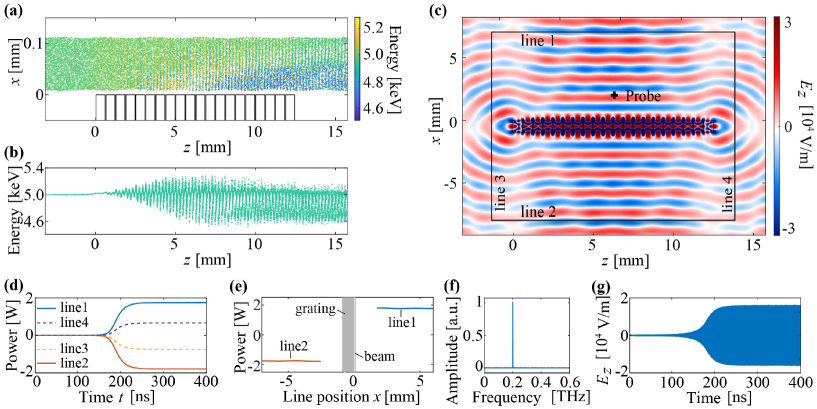
To exemplify the method, the grating period , dutycyle , thickness and the radiation wavelength remain the same as in the previous discussions. For 51 keV electrons, we have . When changing the normalized electron velocity to (), the solution of the dispersion relation for WGA modes stays the same, and thus the operation frequencies of those BIC resonances remain unchanged. In the following example, we set , corresponding to an electron energy of 4.99 keV. Figure 7 shows the corresponding reflection coefficients and , where ranges from to . Compared with the 51 keV case, the locations of the dispersion curves remain the same, but the line widths become narrower. The operation point is then determined by the intersection of the 4.99 keV beam line with one dispersion curve, corresponding to a radiative mode with the -3rd-order space harmonic being the SP radiation. It is still located near a BIC and thus an enhancement of both and can be obtained.
Figures 8 shows the particle simiulation results for 4.99 keV electrons, with the number of grating period , the spacing between the beam and grating , the current density and the other parameters the same as figure 5 . Comparing with the 51 keV case, the spacing between electron bunches reduces to , simply because , as shown in figures 8(a) and 8(b). Figures 8(c) and 8(f) demonstrate that the SP radiation angle and frequency remain the same as in the 51 keV case. Figure 8(d) and 8(e) show the maximum total power for the SP radiation through line 1 and line 2 is about 3.6 W, implying an efficiency of 1.4%, which is lower than that for 51 keV electrons owing to the different reflection coefficients and the smaller transverse extent of the 0th-order space harmonic. We note that in this case the fraction of the power through line 3 and line 4 is relatively high (about 1.3 W), this might be caused by the fact that the number of periods becomes less, leading to a lower quality factor for the grating resonator [54]. Figure 8(g) shows that the field of SP radiation detected by the probe in figure 8(c) also becomes lower.
Thirdly, we consider the interaction with a radiative mode that has more than one propagating space harmonic. Based on (6), with the target operation frequency remaining 0.2 THz, the electron energy and the grating period are changed to 174.6 keV and 1499 , respectively, so that the -1st-order space harmonic can radiate at and -2nd-order at . Figure 9 plots the reflection coefficients , , as a function of grating dutycycle and thickness . BICs can be found at the same locations in the contours of and . In the following, the grating dutycycle is set to be and the thickness , corresponding to a radiative resonance near the BIC located inside the black circle in figures 9(b) and 9(c).
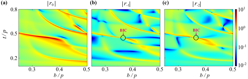
Figure 10 shows the particle simulation results, with the spacing between the beam and grating being , and the number of grating period . With , the spacing between electron bunches is , as shown in figures 10(a) and 10(b). Figures 10(c) and 10(f) demonstrate that the SP radiation indeed includes two diffraction orders (one propagates at and the other at ), and the radiation frequency is about 0.2 THz. Figure 10(d) shows that the maximum total power (667 W, corresponding to an efficiency of 7.6%) through line 1 and line 2 in figure 10(c) is much higher than the total power (23 W) through line 3 and line 4. Because of the oblique radiation angle, the detected power becomes less when line 1 and line 2 move away from the grating, as shown in figure 10(e). Figures 10(g) shows that the field of SP radiation detected by the probe in figure 10(c) becomes stronger with an increasing electron beam current.
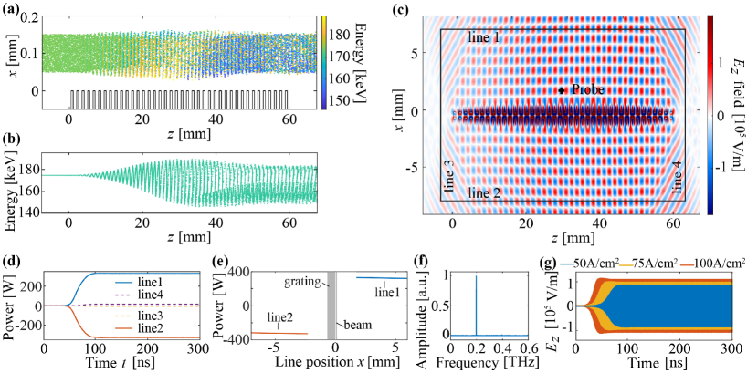
In these particle simulations, special attention should be paid to the electrons’ lateral displacement in the direction. For example, in figure 10(a), the overall beam thickness becomes significantly larger when the electrons start to bunch. This phenomenon is caused by the combined effect of the increasing space-charge repulsive forces between bunched electrons and the lateral deflection force exerted by the and fields of the synchronous 0th-order space harmonic[47]. Such lateral displacement may lead to charging and overheating of the grating, which is undesired for dielectric structures, especially when the spacing between the beam and grating is small. For practical implementation, to sustain the sheet electron beam near the grating, a strong longitudinal magnetic field can be used for transversely confining the beam.
Furthermore, we note that the saturation time of the radiation in figures 5, 8 and 10 are different. The growth rate of the beam-wave interaction is the key parameter that determines the saturation time, which depends not only on the grating structures but also on the electron beam parameters[28]. Generally, enhancing the interaction can improve the growth rate and shorten the saturation time[55]. Although the analysis of growth rate goes beyond the WGA model in this article, a simple method for shortening the saturation time has been revealed by the particle simulation, i.e., increasing the current density as shown in figures 5(g) and 10(g) [56].
5 Conclusion
We have investigated a radiating source using a BIC resonance of a single open grating to interact with a continuous electron beam.Theoretical analysis using the mode-matching method shows that the BIC resonance can be obtained by engineering the interference of WGA modes. Particle simulations indicate the feasibility of producing coherent SP radiation in the presence of interaction between a continuous electron beam and the BIC resonance. For an incident electron energy of 51 keV, the output power of the stimulated SP radiation in the normal direction is 52.8 W with a power conversion efficiency of 2.1 %, promising for practical applications. Employing the 3rd-order space harmonic for SP radiation, the required electron energy can be reduced to 4.99 keV. Moreover, stimulated radiations towards different directions are shown to be possible by utilizing a radiative mode that has more than one propagating space harmonic. This study shows a viable solution towards a low-voltage stimulated radiation source with the merit of simplicity. Extra optimizations of material and structure may further improve the radiation performances and would be considered for future studies.
Acknowledgments
This work was supported by “the Fundamental Research Funds for the Central Universities” (No. 2242020K40022).
References
References
- [1] Garaev D I, Sergeeva D Y and Tishchenko A A 2021 Physical Review B 103(7) 075403
- [2] Pupasov-Maksimov A and Karlovets D 2021 New Journal of Physics 23(4) 043011
- [3] Lin X, Easo S, Shen Y, Chen H, Zhang B, Joannopoulos J D, Soljačić M and Kaminer I 2018 Nature Physics 14(8) 816–821
- [4] Liu F, Xiao L, Ye Y, Wang M, Cui K, Feng X, Zhang W and Huang Y 2017 Nature Photonics 11 289
- [5] Hu H, Lin X, Zhang J, Liu D, Genevet P, Zhang B and Luo Y 2020 Laser & Photonics Reviews 14(10) 2000149
- [6] Liao G, Li Y, Zhang Y, Liu H, Ge X, Yang S, Wei W, Yuan X, Deng Y, Zhu B, Zhang Z, Wang W, Sheng Z, Chen L, Lu X, Ma J, Wang X and Zhang J 2016 Physical Review Letters 116(20) 205003
- [7] Yu Y, Lai K, Shao J, Power J, Conde M, Liu W, Doran S, Jing C, Wisniewski E and Shvets G 2019 Physical Review Letters 123(5) 057402
- [8] Su Z, Cheng F, Li L and Liu Y 2019 ACS Photonics 6(8) 1947–1954
- [9] Roques-Carmes C, Kooi S E, Yang Y, Massuda A, Keathley P D, Zaidi A, Yang Y, Joannopoulos J D, Berggren K K, Kaminer I and Soljacic M 2019 Nature Communications 10(1) 3176 ISSN 2041-1723
- [10] Wang Z, Yao K, Chen M, Chen H and Liu Y 2016 Physical Review Letters 117(15) 157401
- [11] Gardelle J, Modin P and Donohue J T 2010 Physical Review Letters 105(22) 224801
- [12] Aryshev A, Potylitsyn A P, Naumenko G A, Shevelev M, Shkitov D, Sukhikh L G, Terunuma N and Urakawa J 2020 Scientific Reports 10(1) 7589
- [13] Urata J, Goldstein M, Kimmitt M F, Naumov A, Platt C and Walsh J E 1998 Physical Review Letters 80(3) 516–519
- [14] Remez R, Karnieli A, Trajtenberg-Mills S, Shapira N, Kaminer I, Lereah Y and Arie A 2019 Phys. Rev. Lett. 123(6) 060401
- [15] Kaminer I, Kooi S E, Shiloh R, Zhen B, Shen Y, López J J, Remez R, Skirlo S A, Yang Y, Joannopoulos J D, Arie A and Soljačić M 2017 Phys. Rev. X 7(1) 011003 URL https://link.aps.org/doi/10.1103/PhysRevX.7.011003
- [16] Woods K J, Walsh J E, Stoner R E, Kirk H G and Fernow R C 1995 Physical Review Letters 74(19) 3808–3811
- [17] Ye Y, Liu F, Wang M, Tai L, Cui K, Feng X, Zhang W and Huang Y 2019 Optica 6(5) 592–597
- [18] Yang Y, Massuda A, Roques-Carmes C, Kooi S E, Christensen T, Johnson S G, Joannopoulos J D, Miller O D, Kaminer I and Soljačić M 2018 Nature Physics 14(9) 894–899
- [19] Liu W and Xu Z 2014 New Journal of Physics 16(7) 073006
- [20] Song Y, Jiang N, Liu L, Hu X and Zi J 2018 Physical Review Applied 10(6) 064026
- [21] Bratman V L, Fedotov A E, Makhalov P B and Rusin F S 2009 Applied Physics Letters 94(6) 061501
- [22] Liu W, Lu Y, Wang L and Jia Q 2016 Applied Physics Letters 108(18) 183510
- [23] Grishin Y A, Fuchs M R, Schnegg A, Dubinskii A A, Dumesh B S, Rusin F S, Bratman V L and Mobius K 2004 Review of Scientific Instruments 75(9) 2926–2936
- [24] Myasin E A, Evdokimov V V and Ilyin A Y 2016 Radiophysics and Quantum Electronics 59(5) 369–381
- [25] Bratman V L, Dumesh B S, Fedotov A E, Makhalov P B, Movshevich B Z and Rusin F S 2010 IEEE Transactions on Plasma Science 38(6) 1466–1471
- [26] Schächter L and Ron A 1989 Physical Review A 40(2) 876–896
- [27] Andrews H L, Boulware C H, Brau C A and Jarvis J D 2005 Physical Review Special Topics - Accelerators and Beams 8(11) 110702
- [28] Andrews H L and Brau C A 2004 Physical Review Special Topics - Accelerators and Beams 7(7) 070701
- [29] Andrews H L, Boulware C H, Brau C A, Donohue J T, Gardelle J and Jarvis J D 2006 New Journal of Physics 8(11) 289–289
- [30] Kumar V and Kim K 2006 Physical Review E 73(2) 026501
- [31] Shibata Y, Hasebe S, Ishi K, Ono S, Ikezawa M, Nakazato T, Oyamada M, Urasawa S, Takahashi T, Matsuyama T, Kobayashi K and Fujita Y 1998 Physical Review E 57(1) 1061–1074
- [32] Bratman V L, Fedotov A E and Makhalov P B 2011 Applied Physics Letters 98(6) 061503
- [33] van den Berg P M 1973 Journal of the Optical Society of America 63(6) 689–698
- [34] van den Berg P M and Tan T H 1974 Journal of the Optical Society of America 64(3) 325–328
- [35] Haeberlé O, Rullhusen P, Salomé J M and Maene N 1994 Physical Review E 49(4) 3340–3352
- [36] Brownell J H, Walsh J and Doucas G 1998 Physical Review E 57(1) 1075–1080
- [37] Zhang K, ejie, Chang K, Zhang K and Li D 1998 Electromagnetic theory for microwaves and optoelectronics (Springer)
- [38] Rusin F and Bogomolov G 1969 Proceedings of the IEEE 57 720–722
- [39] Chang-Hasnain C J and Yang W 2012 Advances in Optics and Photonics 4(3) 379
- [40] Chen Z, Koyama K, Uesaka M, Yoshida M and Zhang R 2018 Applied Physics Letters 112(3) 034102
- [41] Chen Z, Koyama K, Uesaka M, Yoshida M and Zhang R 2018 Applied Physics Letters 113(12) 124101
- [42] Qiao P, Yang W and Chang-Hasnain C J 2018 Advances in Optics and Photonics 10(1) 180–245
- [43] Wang Z, Zhang B and Deng H 2015 Physical Review Letters 114(7) 073601
- [44] Szczepkowicz A, Schächter L and England R J 2020 Applied Optics 59(35) 11146–11155
- [45] Hsu C W, Zhen B, Stone A D, Joannopoulos J D and Soljačić M 2016 Nature Reviews Materials 1(9) 16048
- [46] Sapra N V, Yang K Y, Vercruysse D, Leedle K J, Black D S, England R J, Su L, Trivedi R, Miao Y, Solgaard O, Byer R L and Vučković J 2020 Science 367(6473) 79–83 ISSN 0036-8075
- [47] England R J, Noble R J, Bane K, Dowell D H, Ng C K, Spencer J E, Tantawi S, Wu Z, Byer R L, Peralta E, Soong K, Chang C M, Montazeri B, Wolf S J, Cowan B, Dawson J, Gai W, Hommelhoff P, Huang Y C, Jing C, McGuinness C, Palmer R B, Naranjo B, Rosenzweig J, Travish G, Mizrahi A, Schachter L, Sears C, Werner G R and Yoder R B 2014 Reviews of Modern Physics 86(4) 1337–1389
- [48] Zhou J, Liu D, Liao C and Li Z 2009 IEEE Transactions on Plasma Science 37(10) 2002–2011
- [49] Liang L, Liu W, Jia Q, Wang L and Lu Y 2017 Optics Express 25(3) 2960
- [50] Liu W, Liang L, Jia Q, Wang L and Lu Y 2018 Physical Review Applied 10(3) 034031
- [51] Zhou Y, Zhang Y and Liu S 2016 IEEE Transactions on Terahertz Science and Technology 6(2) 262–267
- [52] Wagner C and Harned N 2010 Nature Photonics 4(1) 24–26
- [53] Guerrera S A and Akinwande A I 2016 IEEE Electron Device Letters 37(1) 96–99
- [54] Taghizadeh A and Chung I S 2017 Applied Physics Letters 111 031114
- [55] Li D, Hangyo M, Tsunawaki Y, Yang Z, Wei Y, Miyamoto S, Asakawa M R and Imasaki K 2012 Applied Physics Letters 100 191101
- [56] Cao M, Liu W, Wang Y and Li K 2015 Physics of Plasmas 22 083107