Coordinated Container Migration and
Base Station Handover in Mobile Edge Computing
Abstract
Offloading computationally intensive tasks from mobile users (MUs) to a virtualized environment such as containers on a nearby edge server, can significantly reduce processing time and hence end-to-end (E2E) delay. However, when users are mobile, such containers need to be migrated to other edge servers located closer to the MUs to keep the E2E delay low. Meanwhile, the mobility of MUs necessitates handover among base stations in order to keep the wireless connections between MUs and base stations uninterrupted. In this paper, we address the joint problem of container migration and base-station handover by proposing a coordinated migration-handover mechanism, with the objective of achieving low E2E delay and minimizing service interruption. The mechanism determines the optimal destinations and time for migration and handover in a coordinated manner, along with a delta checkpoint technique that we propose. We implement a testbed edge computing system with our proposed coordinated migration-handover mechanism, and evaluate the performance using real-world applications implemented with Docker container (an industry-standard). The results demonstrate that our mechanism achieves 30%-40% lower service downtime and 13%-22% lower E2E delay as compared to other mechanisms. Our work is instrumental in offering smooth user experience in mobile edge computing.
I Introduction
As the next evolution of computing paradigm, mobile edge computing (MEC) brings computation, storage, and communication much closer to end-users [1, 2]. It allows a mobile user (MU) to offload its computationally intensive tasks (e.g., image processing) to nearby edge servers to significantly reduce the end-to-end (E2E) delay as compared to using the cloud counterpart [1]. An edge server hosts multiple containers or offloaded services (the latter is just the former in the running status, so we will use them interchangeably depending on the context), each of which runs a task offloaded by a user. While a virtual machine (VM) creates a full guest operating system (OS), containers are a lightweight virtualization technology that shares the same OS kernel and isolates the application processes from the rest of the system. Therefore, containers not only solve the environment-dependence issue but also notably reduce memory footprint, initialization, and migration overhead [3].
However, when a user who is served by a stateful offloaded service111A stateful service (such as a video game) maintains its state information of users context [4] for future sessions. moves, and if its associated edge server does not change, the latency advantage will start to degenerate toward the original cloud-based offloading and can become even worse [1]. Therefore, it is necessary to perform container migration [5] from the current edge server to another edge server that is closer to the MU, with minimal service interruption (i.e., downtime). Since the moving trajectories of MUs are typically unknown a priori, it is challenging to know the best time and destination edge server to migrate the current container. Furthermore, it is also desirable to be able to migrate over wide area networks (WANs) rather than LANs only [1, 6], which constitutes another challenge.
Besides container migration, the wireless connection between a MU and its associated base station (BS)—cellular BS or WiFi access point—needs to be handed over to another BS as well (note that a BS may or may not be collocated with an edge server). Although handover has been well studied in cellular networks [7], the key difference here is that, in MEC, the handover between BSs takes place in conjunction with container migration between edge servers, while in cellular networks, all computation tasks are hosted in a central server and hence there is no need for migration. Therefore, the handover process and the migration process need to be coordinated with optimized timing and destination hosts in order to achieve minimal service downtime and provide smooth user experience.
Our main contributions are as follows:
-
•
We present a MEC architecture that assists container migration and BS handover (as well as monitoring and deployment) for MUs with user context transfer (Section III).
-
•
We propose a coordinated migration-handover mechanism to minimize E2E delay and service interruption. The mechanism consists of two parts: (i) Optimal Placement which determines the best destination edge servers for migration and the best BSs for handover (Section IV-A); and (ii) Best Triggering Time which determines the coordinated time to trigger various stages of the migration process (based on our proposed delta checkpoint technique) and the handover process (Section IV-B).
-
•
We built a MEC testbed, implemented our proposed coordinated migration-handover mechanism, and evaluated its performance using real-world applications that we developed. The experimental results show that the proposed mechanism outperforms one baseline and two state-of-the-art mechanisms (Section V). The open-source code is available at https://gitlab.com/ngovanmao/edgecomputing.
II Related Work
VM migration on edge computing system has been considered in several works [8, 3, 9, 10, 2, 6, 11, 12]. However, most of the systems [8, 3, 10, 11] focus on VM migration over LANs which is more relevant to cloud computing; some [12, 9, 2] consider computation task offloading for mobile users but have overlooked the network condition of mobile devices. Nasrin et al. [11] proposed a SharedMEC system to reduce unnecessary migrations during handover among femtocell BSs. In our work, we consider a comprehensive system including both placement and migration of stateful offloaded services (i.e., containers), together with handover of wireless connections for mobile users. Prior work evaluates the performance of migration using simulations [10, 8, 11], whereas we evaluate both migration and handover using an actual MEC testbed with real applications deployed as Docker containers. In addition, some papers describe MEC architectures but without migration for MUs, whereas we present an architecture that fills this gap. Finally, we jointly minimize E2E delay and total service downtime by taking both theoretical and practical approaches.
III Edge Computing System Architecture
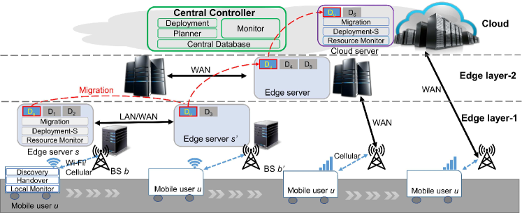
We present a hierarchical MEC system including three layers as shown in Fig. 1. The layer-1 edge servers are collocated with BSs at the access network. The layer-2 servers are further away from MUs but have more computational power; they are fewer and connect to sparsely distributed BSs (such as in rural areas) which are not collocated with edge servers. Cloud resides at the third and highest layer, and hosts one or more (cloud) servers or VMs that have the same internal modules as the edge servers.
The cloud hosts a single central controller which maintains a global view of the whole system. It gathers information from all the edge servers, BSs, and MUs, and stores it in a Central Database. The Deployment module listens to and receives offloading requests from MUs, invokes a Planner module to find an edge server for placing offloaded services, and issues this instruction to the corresponding edge server. The Monitor module monitors MU-related performance such as E2E delay and received signal strength indication (RSSI). If the performance fails to meet a pre-defined service level agreement (SLA), or the MU needs a handover, it triggers the Planner module to find a better placement scheme. The Planner module combines all the monitored information to make a migration-handover plan which includes: placement of edge server (where to host the container), placement of BS (which BS to connect to the MU), the time of migration, and the time of handover.
An edge server uses a Deployment-S module to deploy the container based on instructions issued by the central controller, notify ready-to-use to MUs, and update its status to the central controller. The Resource Monitor module monitors the resource utilization with respect to computation, memory, storage, and network of the edge server and its containers. The Migration module on the source and destination edge servers collaborate with each other to migrate containers based on instructions from the central controller.
Mobile users use a Discovery module to request to the MEC system for offloading tasks. The Local Monitor module regularly sends E2E delay and RSSI with respect to nearby BSs to the central controller.
Our MEC system design follows the ETSI specifications on application mobility service [4] with the implementation approach of MEC assisted user context transfer.
IV Design of Coordinated Mechanism
IV-A Optimal Placement
This subsection deals with determining the optimal destinations—edge servers and BSs—for migration and handover. The objective is to maintain a low E2E delay for MUs with minimal service interruption.
Consider a MEC system that consists of a set of MUs a set of BSs , and a set of servers . We let include the cloud server as well because it is the same as an edge server except for different resource capacities. At time , a MU who is connected to a BS continuously offloads tasks to an offloaded service deployed on a server as a container . Denote by whether or not is connected to the BS , and its offloaded service is allocated to the server , at . Denote by the E2E delay which is defined as the interval between time when sends an offloading task to a server via its associated BS , and the time when receives a task execution result from some server via some BS.
Suppose at a future time , the MU moves from the current BS to the vicinity of another BS . We need to find a new server to host the container and a new BS to keep the wireless connection for the MU. In short, we need to find a new variable at . As a result of this migration and handover, the change of the E2E delay is , which takes into account both computation and communication aspects. Throughout this paper, we use the symbol hat () to denote estimation because is a future time. The total gain obtained from the migration and handover is thus defined by
| (1) |
where is the estimated total number of tasks that are offloaded from the MU via the new BS to the new server at the future time . Since only for and that associate with the user , we can reduce (1) from the first equation to the second equation. Note that if continuously offloads tasks to server via BS , it will likely offload a similar number of tasks to the new server via the new BS . Hence we assume .
Besides the gain, migration and handover will also cause service interruption which can be measured by the total service downtime. This downtime starts when ’s container becomes unavailable (due to connection being handed over from BS to , or container being migrated from server to ), and ends when the service becomes available again. Hence we denote it by . Thus, the total cost of the migration and handover is defined by
| (2) |
Our objective is to maximize total profit, defined as
| (3a) | ||||
| subject to: | ||||
| (3b) | ||||
| (3c) | ||||
| (3d) | ||||
| (3e) | ||||
The constraint (3b) says that an offloaded service must be hosted by a single server, and a MU is associated with a single BS. The constraint (3c) means that the total resources required by ’s containers , i.e., , does not exceed the server’s resources , where the resources include CPU, memory, storage, and network I/O. The constraint (3d) imposes that the MU is not to be associated with a BS if either the measured RSSI or estimated RSSI is below the minimum RSSI required by the receiver in order to decode signal. The constraint (3e) means that a BS can serve a maximum number of MUs.
In the above, all the parameters at time are known and obtained by querying the central database. For the parameters at time , how to estimate the change of E2E delay, as in (1), and the service downtime, as in (2), are presented in Section IV-A and Section IV-B, respectively.
The problem (3a) is a multidimensional Knapsack problem which is NP-hard [13]. Hence, we use the mixed-integer programming open-source solver CBC[14] to find a numerical solution. In particular, we are interested in the case of which means that the user is connected to BS and allocated an offloaded service to server at the future time . Based on our experimental observations, there always exists a feasible solution, i.e., migration-handover plan, for MUs.
End-to-End delay analysis: At a future time , the estimated E2E delay consists of four components: processing, transmission, propagation, and queuing delays. The processing delay is the duration of executing an offloading task on the edge server which depends on the computational power of the server, and can be estimated as , where are the computational power of the source server and that of the destination server , respectively, and can be measured using benchmarking software222One such example is sysbench, and it needs to run once on each server.. The transmission delay is the time to transmit the offloading task and receive the task execution result, and can be estimated as where is the (estimated) task size, is the estimated bandwidth. The bandwidth between the MU and BS can be estimated based on the and the access wireless technology [15], and the bandwidth between BS and server can be obtained by querying the central database. In estimating , we ignore the transmission delay of the task execution result due to its much smaller size compared to the task itself. The propagation delay is the round-trip time (RTT) of propagating a single bit between the MU and the server. It includes two parts: (1) between the MU and the BS via wireless, which can be neglected due to the very short distance as compared to the speed of light, and (2) between the BS and the server via wired network, which can be far away from each other, as is denoted by . For queuing delay, we assume for simplicity that it remains the same before and after migration. Finally, the change of E2E delay is estimated as:
| (4) | ||||
We note that it could be negative if the migration decision is not made properly.
IV-B Best Triggering Time
This subsection determines the best time to trigger BS handover and the best time to trigger container migration. We propose a technique called delta checkpoint to perform container migration for stateful applications, which consists of two phases:
-
•
Pre-migration phase: in this phase, we checkpoint (i.e., snapshot the memory of) the current container and transfer the whole memory state to the destination server, while leaving the container continue to run.
-
•
Migration phase: we checkpoint the container again and save the difference between this and the previous checkpoint as a delta memory state, which is much smaller than the memory state in the pre-migration phase and is transferred to the destination server.
Note that in the delta checkpoint technique, we assume that base container images333A container image is an immutable file that contains a snapshot of a container. are available at the source and destination servers (which can be done by downloading in advance). Recall that at a future time , a MU moves from the current BS to the vicinity of another BS . We need to estimate the time taken for migrating ’s container from server (which is connected to ) to (which is connected to ). This total migration time is a sum of pre-migration time and migration time, i.e.,
where:
| (5) | ||||
| (6) |
In the above,
-
•
is the checkpoint time which depends on the size of the container image and computational power of the source server;
-
•
is the time to transfer pre-migration’s checkpointed files with the estimated size over the network bandwidth between the two servers;
-
•
is the time to transfer which is the estimated size of delta memory state between the migration’s checkpointed files and the pre-migration’s checkpointed files;
-
•
is the time to restore the migrated container at the destination server.
The parameters and can be inferred by using the historical information of checkpoints and restores of all containers hosted on the server .
Estimating the size of delta memory state is hard because it varies substantially between different computation tasks, making static information (e.g., container image size) much less instrumental. To solve this problem, we use a heuristic technique as follows. After the container processes the MU ’s tasks for a certain period of time, say at the time , the hosting edge server triggers two consecutive checkpoints to while leave it running. Then the server measures the size of the two checkpointed files, where the first is and the difference between the two is the delta memory state . Thus, we estimate the size of pre-migration checkpoint and the size of delta memory state to be and , respectively.
The time to handover the connection from the BS to , which we denote by , can be estimated using the relative RSSI hysteresis technique [16].
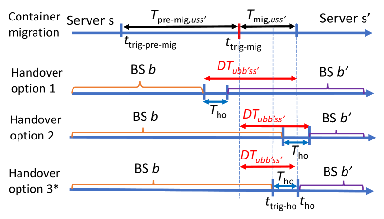
Based on the above estimates, we explain how to trigger handover and container migration in an orchestrated manner in order to minimize total service downtime. When the MU moves from the BS to , the container is either migrated to another server , or still running at the old server that can be considered as a special case of the former when . The order of triggering handover and migration processes can significantly affect the total service downtime. As shown in Fig. 2, the first timeline describes the container migration process including pre-migration and migration. The second and third timelines describe early and late triggering of handover, respectively, and it shows that the total service downtime is larger than the maximum of the migration time and the handover time (). Only the fourth timeline presents the best time to trigger handover, which achieves the minimal total service downtime as is estimated to be
So, in our proposed migration-handover mechanism, the time to trigger pre-migration, migration and handover, with a 10% error margin, is given as in the first timeline, and in the fourth timeline as shown in Fig. 2.
V Performance Evaluation
We implement container deployment using Docker [17] which is widely adopted in the industry. We implement container migration based on our proposed delta checkpoint technique, using an open source tool CRIU [18].
V-A Experiment Setup
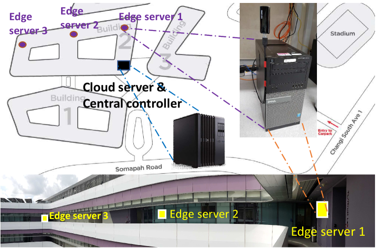
Fig. 3 shows our testbed of the presented MEC system, which includes a cloud server which also runs a central controller, and three edge servers. Each of the three edge servers runs on a 4-core Intel Core i7-4790 3.60 GHz (8 threads) with 16 GB RAM, and the cloud server runs on a 6-core Intel Core i7-6850K 3.60 GHz (12 threads) with 128 GB RAM. We use Linux traffic control tool, tc, to emulate WAN connections [19], where the connection between any two adjacent edge servers is configured as 100 Mbps bandwidth and 50ms latency [6], and the connection between each edge server and the cloud server is configured as 75 Mbps bandwidth and 150ms latency [1].
We implement three applications (available at https://gitlab.com/ngovanmao/edgeapps) to be the services for offloading image processing tasks, and package each into a Docker container:
To simulate stateful applications, all the three applications store and increment counter after each incoming offloading request. The counter is checked before and after migration to ensure consistent state of each offloaded service.
In order to make our experimental results reproducible, we develop a virtual MU in a simulated mobility environment rather than testing an actual smartphone in an actual mobility environment which is subject to many uncontrollable factors. Our virtual MU has all the required functional features and moving behavior of an actual MU. It offloads computational tasks (i.e., image processing) to one of the three real edge servers or a cloud server that we deploy as in Fig. 3. To simulate the handover behavior, we run the virtual MU on a separate computer and use iptable to specify the single-hop traffic path between MU and its associated BS. We also configure each WiFi AP as a network address translation (NAT) router to specify the single-hop traffic path between the MU’s associated BS and the MU’s offloading server.
The MU uses the path loss model [7] to generate RSSI values which will be used to trigger handover. The handover time of the virtual MU is set to 500ms [22]. To simulate moving, we let MU continuously make round-trips between the starting point and the end point, as shown in Fig. 3. The velocity is set to 0.5 m/s in the cases of Openface and Yolo, and 1 m/s in the case of Simple. We run each experiment for 1600s.
We implement four Planner modules under the Central Controller (see Fig. 1) for comparison: (1) Cloud planner: always allocates a container to the cloud (i.e., no migration) regardless of location of MUs. (2) Random planner: allocates a container to a randomly-chosen server. (3) Nearest planner: allocates a container to the nearest server of the MU. (4) Orchestrated planner: allocates a container and handovers BS connection using our proposed mechanism (Section IV). The first three planners are triggered when BS handover is triggered due to low RSSI signal.
V-B Experiment Results
We evaluate the above MEC system in terms of two performance metrics: E2E delay and total service downtime experienced by MU.
V-B1 End-to-end delay
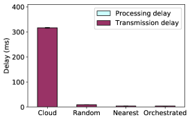
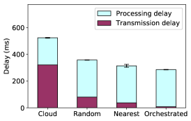
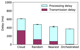
First, we show the statistical results of E2E delay (which consists of mean processing delay and mean transmission delay) of a MU who offloads tasks to one of the three offloaded services under four evaluated planners in Fig. 5. As we can see, the cloud planner incurs significant high E2E delay in which the long transmission delay dominates the short processing delay. In Fig. 4a, the E2E delay of Simple service reflects the network configurations of the testbed since there is no processing delay. As shown in Figs. 4b, 4c, the processing delay under the random, nearest, and orchestrated planners are more or less the same, but the transmission delay under the orchestrated planner is significantly lower than that under the random and nearest planners. For example, for Openface service, the transmission delay under the orchestrated planner is just 10%, 22% of that under the random and nearest planners, respectively. As a result, the MU under the orchestrated planner achieves the lowest E2E delay. For Yolo service, the E2E delay under the orchestrated planner is 22.2% and 12.6% lower than that of the random and nearest planners, respectively.
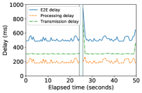
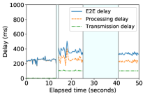
Second, we zoom in onto a 50 s interval for a closer investigation of the E2E delay (including its two components) of a MU who offloads tasks to Openface service under four planners in Fig. 6. During this period, the MU moves from one BS to another BS. In Fig. 6a, the cloud planner incurs much longer transmission delay despite its slightly shorter processing delay, resulting in a much higher E2E delay in comparison with the other planners.
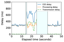
As shown in Fig. 6b, the random planner has a fluctuating E2E delay. Although, before BS handover, the random planner may obtain low E2E delay by occasionally allocating the container to a nearby edge server, the E2E delay is significantly increased after BS handover because the next offloading server can be the old edge server or another server that is far away from the MU.
For the random planner and the nearest planner, we can see in Figs. 6b, 6c that during the handover period, the E2E delay are significantly elevated. This is mainly due to the much prolonged transmission delay after the MU handover to a new BS but the offloaded service is still running on the previous server (i.e., not migrated yet).
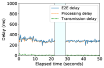
As shown in Fig. 6d, the orchestrated planner has less fluctuation in E2E delay than the other planners, which implies a much smoother user experience. This is because the orchestrated planner always allocates containers to the best server, and initiates container migration at the coordinated time with BS handover. Also because of the coordinated migration-handover mechanism, after the MU handover to a new BS, the server has also been migrated and hence the transmission delay is minimized. Overall, the orchestrated planner achieves the lowest E2E delay among all the planners.
V-B2 Total service downtime
Fig. 6 also shows the service downtime (indicated by the shaded gaps) experienced by the MU who offloads tasks to Openface service under four planners. The cloud planner has the shortest total service downtime because it only requires BS handover and not container migration. However, it has significantly longer E2E delay as indicated in both Fig. 5 and Fig. 6. Now we zoom onto the service downtime of the other three planners which involves both container migration and BS handover. We see in Fig. 6 that the random and nearest planners have a large total service downtime consisting of two separate periods, i.e., handover and migration periods. Between the two periods, the offloaded service is still hosted on the old server (and under pre-migration phase), hence leads to a higher E2E delay as shown in Figs 4b, 4c. In contrast, the orchestrated planner has a single and shorter downtime period, due to its orchestrated timing that takes into account both migration and handover.
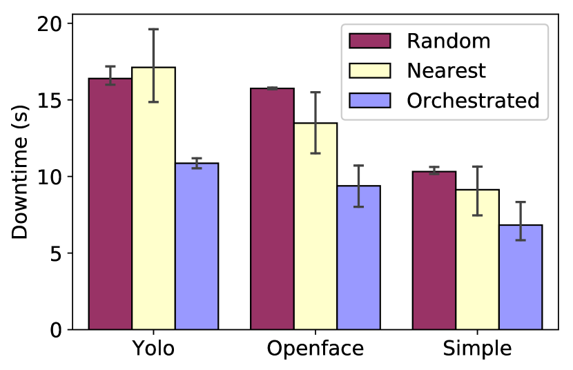
Fig. 5 shows the total service downtime of a MU who offloads tasks to one of the three offloaded services under three migration planners over the whole experiment period. We can see that, in all three offloaded services, the orchestrated planner outperforms the random and nearest planners by reducing the total service downtime by 30-40%.
| Docker | Docker | Checkpoint of | Checkpoint | Reduction |
|---|---|---|---|---|
| container | image size | pre-migration | of migration | ratio |
| Simple | 74.2 MB | 11.29 MB | 47.7 KB | 99.6% |
| Openface | 1.86 GB | 196.8 MB | 7.94 MB | 96.0% |
| Yolo | 792 MB | 584.8 MB | 5.60 MB | 99.1% |
An important determining factor of the duration of migration, which contributes to the total service downtime, is the size of checkpoint files transferred during pre-migration and migration. Therefore, we also present these details in Table I. As we can see, with our proposed delta checkpoint technique for container migration, the size of checkpoint files of migration is significantly smaller than that of the checkpoint files of pre-migration. Specifically, the migration of Openface and Yolo services only transfer 7.94 MB and 5.6 MB which are just 4% and 0.9% of the pre-migration’s checkpoint files. This remarkably helps to reduce the migration time and hence minimize the total service downtime.
In summary, the orchestrated planner with the delta checkpoint technique not only achieves the lowest E2E delay but also minimizes the total service downtime during BS handover.
VI Conclusion
To address the joint challenge of performing container migration and base station handover, this paper proposes a coordinated migration-handover mechanism enabled by a hierarchical MEC system architecture. We (1) formulate an optimization problem for container placement and base station allocation, and (2) derive the best time to trigger handover, pre-migration, and migration, based on a delta checkpoint technique that we propose. We then set up a real MEC testbed, and implement our proposed mechanism in an orchestrated planner as well as three other baseline planners for comparison. The experimental results demonstrate that our proposed mechanism outperforms other solutions by significantly reducing E2E delay and service downtime for mobile users. Our work contributes toward offering much smoother user experience in MEC, especially for time-sensitive applications.
References
- [1] Z. Chen and et al., “An empirical study of latency in an emerging class of edge computing applications for wearable cognitive assistance,” in Proc. ACM/IEEE SEC, 2017.
- [2] S. Duqennoy and et al., “D2.1: Initial design of 5G-CORAL Edge and Fog computing system,” H2020 5G-Coral Project, Tech. Rep., 2018.
- [3] A. Machen and et al., “Live service migration in mobile edge clouds,” IEEE Wireless Communications, vol. 25, no. 1, pp. 140–147, Feb. 2018.
- [4] ETSI-GS-MEC-021, “Multi-access edge computing (MEC); application mobility service api,” v2.1.1, Jan. 2020.
- [5] A. Mirkin, A. Kuznetsov, and K. Kolyshkin, “Containers checkpointing and live migration,” in Proc. Linux Symposium, Ottawa, Canada, 2008.
- [6] L. Ma, S. Yi, and Q. Li, “Efficient service handoff across edge servers via docker container migration,” in Proc. ACM/IEEE SEC, 2017.
- [7] T. Rappaport, Wireless Communications: Principles and Practice, 2nd ed. Upper Saddle River, NJ, USA: Prentice Hall PTR, 2001.
- [8] L. F. Bittencourt, M. M. Lopes, I. Petri, and O. F. Rana, “Towards virtual machine migration in fog computing,” in Proc. 3PGCIC, 2015, pp. 1–8.
- [9] C. Zhu, G. Pastor, Y. Xiao, Y. Li, and A. Ylae-Jaeaeski, “Fog following me: Latency and quality balanced task allocation in vehicular fog computing,” in Proc. IEEE SECON, June 2018, pp. 1–9.
- [10] X. Sun and N. Ansari, “Primal: Profit maximization avatar placement for mobile edge computing,” in Proc. IEEE ICC, 2016.
- [11] W. Nasrin and J. Xie, “Sharedmec: Sharing clouds to support user mobility in mobile edge computing,” in Proc. IEEE ICC, 2018.
- [12] P. Bellavista, A. Zanni, and M. Solimando, “A migration-enhanced edge computing support for mobile devices in hostile environments,” in Proc. IWCMC, 2017, pp. 957–962.
- [13] A. M. Frieze and M. R. B. Clarke, “Approximation algorithms for the m-dimensional 0–1 knapsack problem: Worst-case and probabilistic analyses,” EJOR, vol. 15, no. 1, pp. 100 – 109, 1984.
- [14] COIN-OR, http://projects.coin-or.org/Cbc, accessed Apr. 14, 2020.
- [15] B. Verney, “802.11n + 802.11ac data rates and SNR requirements,” https://higher-frequency.blogspot.com, accessed Sep. 24, 2018.
- [16] S.-J. Yoo, D. Cypher, and N. Golmie, “Predictive link trigger mechanism for seamless handovers in heterogeneous wireless networks,” Wireless Commun. and Mobile Comput., vol. 9, no. 5, pp. 685–703, May 2009.
- [17] Docker, www.docker.com, accessed Apr. 14, 2020.
- [18] CRIU, https://criu.org, accessed Apr. 12, 2020.
- [19] Akamai, “The internet report q1 2017 summary,” www.akamai.com/state-of-the-internet-report, accessed Feb. 24 2020.
- [20] B. Amos, B. Ludwiczuk, and M. Satyanarayanan, “Openface: A general-purpose face recognition library with mobile applications,” CMU-CS-16-118, CMU School of Computer Science, Tech. Rep., 2016.
- [21] S. Mallick, “OpenCV YOLOv3 with CPU,” https://www.learnopencv.com/tag/yolov3/, accessed Aug. 2, 2020.
- [22] A. Mishra, M. Shin, and W. Arbaugh, “An empirical analysis of the ieee 802.11 mac layer handoff process,” SIGCOMM Comp. Comm. Rev., 2003.