A Hierarchical Architecture for Human-Robot Cooperation Processes
Abstract
In this paper we propose FlexHRC+, a hierarchical human-robot cooperation architecture designed to provide collaborative robots with an extended degree of autonomy when supporting human operators in high-variability shop-floor tasks. The architecture encompasses three levels, namely for perception, representation, and action. Building up on previous work, here we focus on (i) an in-the-loop decision making process for the operations of collaborative robots coping with the variability of actions carried out by human operators, and (ii) the representation level, integrating a hierarchical AND/OR graph whose online behaviour is formally specified using First Order Logic. The architecture is accompanied by experiments including collaborative furniture assembly and object positioning tasks.
Index Terms:
Human-robot cooperation; Smart factory; AND/OR graph; Task representation; Online decision making.I Introduction
The paradigm of consumer- and demand-driven manufacturing introduces the need for small-scale, customised, high quality production at lower prices, and with faster delivery times [1, 2]. However, small-scale production does not fully exploit the benefit of robot-based manufacturing yet [3, 4]. Consumer- and demand-driven manufacturing requires robots characterised by high flexibility, fast reconfiguration and installation, as well as low maintenance costs. Collaborative robots are expected to meet such demands, decrease costs, and therefore increase products variability and customisation [1, 2, 3]. In fact, they are considered key enabling factors to automate small-scale production when operations to be carried out are highly dynamic and partially unstructured [5].
Recently, many authors argued that consumer- and demand-driven manufacturing can benefit from the introduction of human-robot cooperation (HRC) processes [6]. HRC assumes that human operators and robots purposely interact in a shared workspace to achieve a common objective. The design of collaborative robots should adhere to a number of human-centric principles. Human-centric design enforces such factors as the explainability of robot decisions, the usability of robot interfaces, the awareness of the cooperation process, and a fair human-robot workload, as well as safety requirements for human operators [7, 8]. On the one hand, since it has been shown that the effectiveness and the overall performance of human operators are positively correlated with robot motion predictability [9], collaborative robots should (requirement ) prevent psychological discomfort, stress, and a high induced cognitive load on human operators [10, 3, 11]. On the other hand, it has been demonstrated that a natural and efficient cooperation is possible only by a reasoned trade-off between the cooperation objective (e.g., the assemblage of a semi-finished product), and the human or robot degrees of autonomy. This is specially true when the task is only partially well-defined (e.g., such assemblage can be done using different action sequences), which can be somewhat enforced or relaxed on a context-dependent basis [12, 13]. Collaborative robots should () be able to react to human operator actions while retaining the capability of planning goal-oriented action sequences [14, 15, 16], and () doing so by abstracting the structure of tasks from perceptual variability and uncertainties [10, 3, 17]. The customised production advocated by consumer- and demand-driven manufacturing still relies on the cognitive capabilities of human operators since collaborative robots are largely unable to efficiently manage inter-tasks or intra-task variations [5]. The ability of human operators to decompose complex tasks into simpler operations (e.g., assembling furniture parts to obtain other semi-finished parts to be used later), or to naturally manage small variations (e.g., assembling furniture with parts of different size, like tables with differing flat top size or leg length), still poses a significant challenge for collaborative robots [18]. As a consequence, collaborative robots () should exhibit decision making capabilities grounded on flexible task representations, and () should enforce a definition of hierarchical action sequences able to map high-level complex tasks to low-level, simple robot operations.
In this paper, we present an integrated architecture for HRC processes, which we refer to as FlexHRC+, aimed at addressing requirements , and outlined above. FlexHRC+ can adapt the behaviour of collaborative robots to human operator actions, while proactively taking decisions aimed at meeting the cooperation goals (addressing ). FlexHRC+ enables online human-robot decision making, a flexible execution of HRC tasks (addressing ), and a hierarchical representation of such tasks enforcing modularity and reuse (addressing ). Our contribution is at two levels.
-
•
Human-robot cooperation level. The first contribution is an in-the-loop, hybrid reactive-deliberative architecture for online, flexible and scalable HRC processes. The architecture is characterised by proactive decision making and reactive adaptation to a perceived sequence of human operator actions or unsuccessful robot operations.
-
•
Task representation level. The second contribution is an integrated hierarchical representation of HRC processes employing First Order Logic (FOL) and AND/OR graphs to model static and dynamic aspects of HRC-related tasks.
With respect to our previous work [16, 17], this paper provides two significant improvements. The former is the use of a FOL-based encoding of information stored in a hierarchical AND/OR graph. The FOL-based task representation has two important consequences. First, it allows for modelling (part of) cooperation tasks on a non-grounded, terminological level, which can be therefore specified as a set of assertions anchored to objects in the robot workspace. This allows for a more compact representation, with a consequent increased flexibility of the whole cooperation process. Second, it decouples the cooperation task from the involved objects. The latter foresees the use of hierarchical AND/OR graphs, which enable a great deal of modularity (when coupled with the FOL-based representation, graphs can be reused in different phases of the cooperation), as well as scalability.
The paper is organized as follows. Section II describes relevant state-of-the-art approaches in HRC processes. Section III introduces the main traits of FlexHRC+. We describe the FOL-based and hierarchical AND/OR graph task representation structure in Section IV, and the task management process in Section V. In Section VI, we describe the experimental scenarios and discuss relevant results. Conclusions follow.
II Related Work
Task representation. Different approaches have been proposed to model HRC processes. Some of them are aimed at introducing aspects of social interaction [19, 20, 21]. Others, similarly to the work described in this paper, focus explicitly on HRC processes for collaborative manipulation or assembly. In this regard, the work in [22] proposed a three-layer framework at the team, agent, and skill execution levels using AND/OR graphs. Task allocation is done by minimizing a cost function offline, whereas the reactive behaviour is managed at the control level. Such a work is extended in [23] where the task allocation is modulated according to the co-worker ergonomics, and where the use of an augmented reality technology combined with the recognition of gestures of the human co-worker allows for an intuitive human-robot interaction. In both contributions, the flexibility aspects and task allocation are restricted to the offline phase. The uncertainties associated with the robot perception and the outcomes of robot actions are merely simplified at the control level. Therefore, the robot does not proactively make decisions. Moreover, the scalability of the solution cannot be easily determined. In our work, we overcome these limitations by addressing the requirements , and with an online task allocation for the human operator or the robot according to both human decisions as they unfold at run-time, and to the robot online simulation results. An example of these advancements is provided in Section VI-D and Section VI-C.
The work presented in [24, 16] is aimed at recognising action sequences performed by human operators online, and to provide robots with methods to adapt accordingly. The recognition of such action sequences assumes actions to be completed before they can be properly recognised. This is expected to introduce possibly unacceptable delays in the cooperation process, and therefore it might jeopardise efficiency and naturalness. A slightly different approach, pursued in [25], employs probabilistic methods and AND/OR graphs to predict human operator actions, thereby trading-off recognition performance and prediction accuracy. In case of wrong predictions, the effectiveness of the overall cooperation process can be negatively affected. Such an approach neither considers the intrinsic uncertainties of robot actions (partially fulfilling ) nor the variations in assembly scenarios (therefore missing ), while the table assembly scenario illustrated in Section VI-D meets those requirements. The approach proposed in [26] envisions a dyadic, mutual adaptation between human operators and robots. Robots act as leaders guiding human operators towards an efficient task execution strategy. It is no mystery that such an approach can lead to a lack of naturalness in the cooperation process. While human action prediction, recognition, and adaptation are forms of implicit human-robot communication, an explicit, speech-based communication is adopted instead in [20, 19]. Aspects related to naturalness are enforced using speech-based communication only in principle. In fact, this is done at the detriment of effectiveness and efficiency, since speech recognition can yield to dramatically poor results in industrial scenarios.
The work in [27] implemented a concurrent, cooperative assembly task with relational Markov Decision Processes (MDPs), taking actions’ duration into account. Using a probabilistic modelling of state transitions, the model can recover from failures in a reactive fashion. However, this is possible by disregarding perception uncertainties. MDPs have been used in [28, 21] to enforce adaptation to human operator behaviours online. Such an approach leads to purely reactive behaviours, which are considered indeed natural, but neither effective nor efficient. In our case, failures are avoided both with proactive decision trees and reactive traversal of an AND/OR graph. Finally, [27] models the cooperation with a tree-like structure whereas, in our case, the AND/OR graph and its hierarchical structure makes the representation compact and modular. This enables the implementation of complex scenarios, such as the one described in Section VI-C.
Task networks and approaches based on classical planning [29, 30] are characterised by a natural description layer based on FOL [20]. Such a layer is expected to enforce effectiveness since it constitutes a close-to-human language used to associate semantics to each robot’s action [31]. A cognitive approach based on an attention-based mechanism is proposed by [32], in which plans are generated using hierarchical task networks, and an attention-based system executes and monitors multiple plans while resolving possible conflicts. To demonstrate capabilities of the approach, a pick and place task in a simulated environment is shown, therefore eliminating intrinsic uncertainties characterising perception and action in real-world environments. Differently from our proposition put forth in Section VI-D, the experiments do not support reactive behaviour or proactive decision making at the team and task levels. Similarly, [33] proposed a collaborative system with a graphical user interface design toolkit for task automation and recognition based on first-order behaviour trees (). Such a collaborative system does not adapt to the intrinsic variability of human decisions or to the workspace status. To accommodate for human preferences, an approach based on a scheduling and control framework has been introduced in [34]. In particular, an optimal scheduling policy embedding temporal constraints and human preferences are learned offline and executed online (partially meeting ). However, it does not support an online adaptation to the possible workspace variability (missing therefore ). Our contribution aims at overcoming these limitations with an online team and task level flexibility. Moreover, none of these works provide evidence for scalability, as shown in Section VI-C.
In order to model action planning in HRC scenarios, hierarchical approaches have been used [20]. The work in [35] took an industry-oriented perspective for human-robot workplace design. It allows for scaling collaboration to complex scenarios using a three-layer task representation approach (). Yet, differently from our approach, as demonstrated in Section VI-C, the one in [35] limits scalability to three-layers at most.
Action planning. As mentioned above, a hierarchical representation allows for the modelling of complex cooperation tasks efficiently, and it enforces modularity and scalability. A few approaches consider the interplay between efficiency and naturalness in the cooperation process [20, 36, 37].
One of the main challenges to address in HRC scenarios is deciding how to allocate actions, either to the human operator, the robot, or in principle to both [12]. When a human operator is given the freedom of autonomously deciding how to accomplish a task, action allocation cannot be defined beforehand and must be resolved online [38, 39]. A multi-objective optimisation problem is typically formulated [39, 35]. It defines a utility measure considering the quality of an action result, its cost, its associated cognitive load, and the resources needed for its completion [40]. Such optimisation problem is then resolved online for dynamic task allocation [41, 39, 42]. Other approaches are limited to offline solutions [35, 22]. As described in [17], which is expanded in this paper, resolving action allocation online can be done only if the relevant parameters of the employed utility measure are either estimated beforehand or it is safe to assume they can be quantified while the cooperation process unfolds.
It is noteworthy that the integration of task representation, online task planning, task allocation, and motion planning is expected to enhance the robustness to failures and the overall HRC process efficiency [17]. It has been shown in [17] that in-the-loop robot motion predictions are beneficial to a natural interaction, as opposed to the prediction of human operator motions [43, 44].
III The FlexHRC+ Architecture
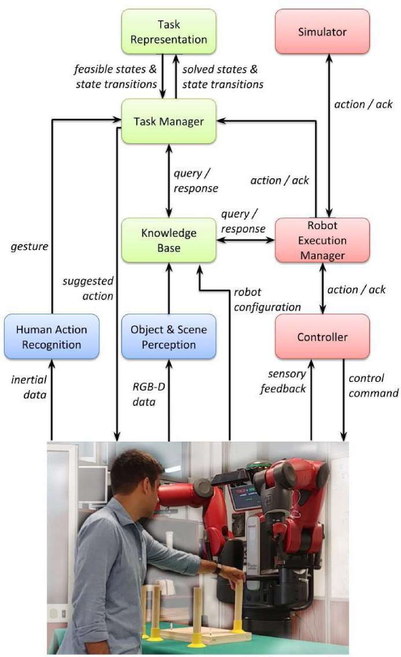
Overview. The architecture of FlexHRC+ is organised in three levels, namely the representation level (depicted in green in Figure 1), the perception level (in blue), and the action level (in red). The representation level maintains all the relevant information related to cooperative tasks via the Task Representation module, and to the shared workspace in the Knowledge Base module. The representation level orchestrates action planning and decision making for task execution, as well as action allocation, via the Task Manager module. The perception level acquires information about the workspace in terms of objects and other entities therein using the Object and Scene Perception module. It is responsible for detecting and classifying actions performed by human operators as done in the Human Action Recognition module. Starting from raw data, the perception level updates the representation level with relevant information about objects and human operator actions. Then, the action level serialises the execution of robot actions (via the Robot Execution Manager module), performs in-the-loop robot action simulations in the Simulator module, and controls online all robot motions using the Controller module.
Representation level. The Task Representation module maintains knowledge about all possible states and state transitions modelling cooperative tasks. The module also defines how the HRC process can progress by providing suggestions to the human operator or commands to the robot about what to do next. As anticipated above, we apply AND/OR graphs, primarily introduced by [45], to represent cooperative tasks [16], as better described in the next Section. The module receives as input the current cooperation status from the Task Manager, and therefore provides it with next action suggestions. The Task Manager module maps cooperation states as represented in the AND/OR graph structure to either human or robot actions. The module plans for suggested states receiving appropriate information from the Task Representation module, it grounds action parameters to actual values, and it performs action assignments on the basis of incoming perceptual information [16, 17]. The Knowledge Base module explicitly represents the cooperation state and workspace-related perceptual information using custom data structures [17].
Perception level. The Human Action Recognition module provides FlexHRC+ with information about actions performed by human operators. The module models action templates using Gaussian Mixture Models and Gaussian Mixture Regression. Models originate from a dataset of inertial data obtained using operator-worn sensors, and applies online a pattern matching algorithm to detect and recognise meaningful actions as performed by human operators [46]. To do so, the module receives an inertial data stream, and informs the Task Manager about the detected and recognised human operator actions [47, 16]. The Object and Scene Perception module provides information about objects in the robot workspace and models them using a set of primitive shapes characterised by their geometrical characteristics. The module simply applies Euclidean distance to cluster a point cloud originating from an RGB-D sensor located on the robot body, it applies the Random Sample Consensus (RANSAC) algorithm to model those clusters as primitive shapes, and it determines their relevant features. Additionally, Principal Component Analysis is used to find complementary object features for manipulation purposes. Recognised objects and their features are maintained in the Knowledge Base module [48, 49, 50].
Action level. The Robot Execution Manager maps action commands issued by the representation level to control actions fed to the Simulator or the Controller module. Each control action is associated with a hierarchy of equality or inequality control objectives. These include reaching a desired end-effector position, avoiding obstacles and joint limits, or respecting the kinematic constraints imposed by a rigid object manipulated by two arms.
In order to execute each control action, the Controller module exploits a kinematic task-priority based framework [51, 52], which solves a sequence of prioritized optimization problems, computing the reference velocities for robot’s actuators. The workspace-related feedback necessary to execute an action is received from the Knowledge Base. The task-priority framework allows for the activation and deactivation of such inequality objectives as, e.g., maintaining a minimum distance from obstacles or from humans without over-constraining the solution when it is not necessary, hence those objectives can be put at the highest priority, increasing the safety of the system. Other safety and compliance features such as detecting and responding to contacts and impacts, preventing from applying continuous or excessive pressure, or keeping impact forces below design limits, are more related to the robot dynamic control, and are usually implemented within low-level control architectures. Therefore, they are not the focus of this paper.
The in-the-loop Simulator module replicates Controller operations, integrating its output to simulate the robot behaviour online. It receives reference information from Robot Execution Manager, and provides it with the results of the simulation, e.g., failure/success of a given command, action execution time, final robot pose, or estimated energy consumption [17].
IV The Human-Robot Cooperation Model
IV-A Single-layer AND/OR Graphs
In order to formalise the human-robot cooperation process in FlexHRC+, we adopt AND/OR graphs. An AND/OR graph allows for an easy decomposition of problems and procedures in their building blocks (as parts of the graph), as well as the logic relationships among them (i.e., the graph connectivity). Since in AND/OR graphs the root node represents the solution to the problem being modelled, solving it means traversing the graph from leaf nodes to the root node according to its structure. AND/OR graphs can take limited forms of non-determinism or uncertainty into account [45, 53, 31] via the availability of various branches leading to the solution. In previous work [16, 17], such representation has been adopted to model the online behaviour of simple cooperation processes. In this paper we systematise the original formulation and extend it along two directions: first, we provide a conceptualisation of AND/OR graphs compatible with a FOL-based task representation framework, which allows us to better model cooperation templates; second, we introduce and analyse the benefits of hierarchical AND/OR graphs to support modular, scalable, and flexible task representation.
An AND/OR graph can be formally defined as a tuple where is a set of nodes, and is a set of hyper-arcs. An hyper-arc induces two sets of nodes, namely the set of its child nodes, and the singleton made up of a parent node, such that
| (1) |
For the scenarios we consider, at the semantic level each node represents a particular state related to the cooperation between a human operator and a collaborative robot. Each hyper-arc represents a (possibly) many-to-one transition among states, i.e., activities performed by human operators or robots that make the cooperation move forward. In FlexHRC+, a node is associated with a conjunction of literals, such that
| (2) |
where each literal may consist of variables, constants or logic predicates, also negated. As it will be described later, each literal can be considered a representation fragment related to the cooperation state defined by . As a consequence, we will refer to as the cooperation state represented in . It is noteworthy that a given does not have to include only grounded literals, i.e., constants or grounded predicates. It can include variables as well, and as such the corresponding node can be treated as a class of states (or cooperation templates) at the Task Representation level [31].
Using the definition of state in (2), it is possible to better specify the state transition in (1). This is a relationship induced on hyper-arc between a set of requirements made up by joining all the literals defining states associated with all the nodes , and a set of effects made up by the state associated with single node , such that
| (3) |
The relation among child nodes in hyper-arcs is the logical and, whereas the relation between different hyper-arcs inducing on the same parent node is the logical or. Different hyper-arcs inducing on the same parent node represent alternative ways for a cooperation process to move on. We define as a leaf node if is not acting as a parent node for any hyper-arc, i.e., if does not exist such that . Similarly, we define as a root node if it is the only node that is not a child node for any hyper-arc, i.e., if does not exist such that .
Each hyper-arc implements the transition in (3) by checking the truth values associated with all the requirements defined by nodes in , executing a number of actions associated with , and generating effects compatible with the cooperation state of the parent node. In particular, each hyper-arc is responsible for executing an ordered set of actions, such that
| (4) |
where the precedence operator defines the pairwise expected order of action execution. Before an hyper-arc is executed, all actions are marked as undone, and we refer to this using a predicate . When one action is executed either by the human operator or the robot, its status changes to done as . An hyper-arc is marked as solved, i.e., iff all actions are done in the expected order.
In a similar way, nodes may be associated with a (possibly ordered) set of processes , i.e.,
| (5) |
Differently from actions, which are instrumental to perform transitions from one cooperation state to another, and must be necessarily executed by human operators or robots, processes are robot behaviours which do not imply any state transition. They are used to control physical or other non-functional variations of some quantity over time. An example may be a robot behaviour aimed at keeping a certain object in a given pose or configuration using two grippers, the effects of external forces notwithstanding, because the related cooperation state assume that object pose. Processes are meant at being executed by robots, whereas a human operator may carry them out occasionally. Each process is characterised by a priority, or precedence. Actions and processes are associated with hyper-arcs and states, respectively. However, there is no causal relationship between actions and processes, hence, they can be executed in any order, according to the priority or preference. When a node is reached, all of its processes are activated, i.e., for each . A process can be deactivated when certain process-specific termination conditions are met, i.e., . A node is marked as met, i.e., , if all the associated processes are deactivated if necessary in the prescribed order, or is an empty set.
Using these definitions, it is possible to introduce the notion of feasibility for nodes and hyper-arcs. A node is feasible, which we refer to as , iff a solved hyper-arc exists, for which , and , i.e.,
| (6) |
All leaf nodes in an AND/OR graph are usually feasible at the beginning of the human-robot cooperation process, which means that the cooperation itself can be performed in many ways, and is not constrained to follow certain sequences of operations. In a similar way, an hyper-arc is feasible, i.e., , iff for each node , and , i.e.,
| (7) |
Once an hyper-arc is solved, all other feasible hyper-arcs , which share with at least one child node, i.e., , are marked as unfeasible, in order to prevent the cooperation process to consider alternative ways to cooperation that have become irrelevant.
The human-robot cooperation process is modelled as a graph traversal procedure. Starting from a set of leaf nodes, it must reach the root node by selecting hyper-arcs and reaching states in one of the available sequences, depending on the feasibility statuses of nodes and hyper-arcs. To this aim, each node is associated with a weight , and each hyper-arc is similarly associated with a weight . Weights are related to the number, difficulty or time-to-completion of actions/processes, and to other more qualitative metrics related to human operator preferences [54]. Nodes or hyper-arcs with lower weights are privileged compared to others with higher weights. Weights are identified through several demonstrations of expert users. Then, a cooperation path induced by is a set of nodes and hyper-arcs, such that
| (8) |
which represents a particular way to connect leaf nodes to the root node. We refer to the set of cooperation paths induced by as , where each element is in the form described by (8). According to the structure of the modelled human-robot cooperation task, multiple cooperation paths may exist, meaning that multiple ways to solve the task may be equally legitimate. Each cooperation path can be associated with an overall cost , such that
| (9) |
The different cooperation paths in can be ranked according to their overall costs. Two cooperation paths and are equal iff the corresponding sets of nodes and hyper-arcs are the same, and are equivalent iff their corresponding overall costs are the same.
The traversal procedure dynamically follows the cooperation path that at any time is characterised by the lowest cost. The traversal procedure suggests to human operators actions in the hyper-arcs that are part of the path, and sends to robots actions they must execute. Human operators can override the suggestions at any time, executing different actions, which may cause the system to be in a cooperation state not part of the current cooperation path. When this situation is detected, FlexHRC+ tries to progress from that state onwards [16, 17]. This mechanism enables FlexHRC+ to pursue an optimal path leading to the solution, while it allows human operators to choose alternative paths when they deem it fit. As long as the human-robot cooperation process unfolds, and the AND/OR graph is traversed, we refer with and to the sets of currently feasible nodes and hyper-arcs, respectively. In fact, the actual elements of these two sets depend on the evolution of the cooperation process.
We say that an AND/OR graph is solved, and we write , iff its root node is met, i.e., . Otherwise, if the condition (i.e., there are no feasible nodes nor hyper-arcs) then the human-robot cooperation process is failed, because there is no feasible cooperation path leading to the root. It is noteworthy that representations based on AND/OR graphs, when updated online, do not require the full knowledge of the robot workspace. In fact, while a given cooperation path is followed, the traversal algorithm only needs knowledge about feasible nodes and hyper-arcs for making the task progress.
The AND/OR graph structure presented in this paper is based on the one introduced in [16]. Notable differences are the possibility of allowing for multiple hyper-arcs connecting the same child nodes to a parent node, ensuring the minimum cost returned from each hyper-arc or node, and supporting a FOL-based task representation. The first feature allows the AND/OR graph to model different state transitions from one cooperation state to another, the second one ensures an optimal, predictable, and therefore explainable robot behaviour, whereas the last one increases the overall expressive power of the representation structure.
The single-layer AND/OR graph traversal procedure is composed of two phases, the first being offline and the second online. The offline phase loads the description of the AND/OR graph, generates the data structure , sets the graph status as unsolved. Later, the feasibility of all nodes and hyper-arcs is checked, the set of cooperation paths is generated, and suggestions for next actions (in terms of nodes and hyper-arcs) are computed as defined in (9).
The update of feasibility statuses of all the involved nodes and hyper-arcs, i.e., populating the corresponding sets and , is done simply by iteratively invoking two functions, namely updateNodeFeasibility() and updateHyperarcFeasibility(). The two functions are further developed in Algorithm 1 and Algorithm 2. Given a node and a hyper-arc the two Algorithms use such predicative knowledge on and as the values of , , , and to update the feasibility of graph nodes and hyper-arcs, respectively, therefore producing updated sets and . In Algorithm 1, lines 3-19 update the feasibility status of a relevant hyper-arc when and holds true. In case node holds false (lines 20-32), lines 21-23 change the node feasibility when it does not have any child node, i.e., if is not a parent of any hyper-arc. Lines 24-31 check for a solved hyper-arc connected to node , and in case at least one of such hyper-arcs exists, then it is marked as feasible. In Algorithm 2, lines 2-13 update the feasibility statuses when the hyper-arc is solved. The feasibility of the ’s parent node (line 3) is updated in lines 4-7. The feasibility of all the hyper-arcs having a common set of child nodes with is updated in lines 8-13. Lines 14-27 check the feasibility of the unsolved hyper-arc . If a child node of (line 17) is not met (lines 18-21) or there is another solved hyper-arc with a set of child nodes common with (lines 22-25), the hyper-arc becomes infeasible. Finally, findSuggestions() in Algorithm 3 determines the set of suggestions whose elements are generically indicated using , and their associated cost . There might be different paths from or to the root of . Therefore, the AND/OR graph is expected to provide the minimum cost among all these cooperation paths to ensure optimality. The cost for a node or hyper-arc is the minimum cost of the cooperation path which the node or the hyper-arc belongs to. Therefore the Algorithm guarantees the optimality of the AND/OR graph because for all nodes or hyper-arcs in or , respectively, it holds that:
| (10) |
In Algorithm 3, lines 3-11 return feasible nodes and the minimum cost of the cooperation paths which include them. The same applies to hyper-arcs in lines 12-20.
The online phase follows Algorithm 4. The two sets of met nodes and solved hyper-arcs are referred to as and , respectively. Upon the reception of the Task Manager’s query, the Algorithm updates node and hyper-arc statuses (in terms of solved, met and feasible predicates) in lines 2-9. The solved status for the whole AND/OR graph is checked. If the root node is met, then the graph is marked as solved (line 11). Otherwise, line 14 updates all the path weights, which include nodes in and hyper-arcs in . In line 15 the new feasible nodes and hyper-arcs, and their associated costs, are made available. In the Algorithm, the functions metNode(, ) and solvedHyperarc(, ) check first if or hold true, then update by and . In particular, updateAllPaths(, , ) updates the cooperation path costs at each query. For a given cooperation path , the path cost at each moment is the cost of traversing it from the current to the root state. Initially, all the path costs are computed from the leaves to the root using (9). When a node or hyper-arc belonging to a given cooperation path is met or solved, its overall cost is reduced of an amount related to its weight, i.e.,
| (11) |
IV-B Hierarchical AND/OR Graphs
The use of hierarchical AND/OR graphs in the context of HRC tasks has two motivations. The first is related to the computational complexity of single-layer AND/OR graphs, while the second is related to flexibility and scalability requirements. It has been shown that AND/OR graphs are characterised by a polynomial time complexity in the number of nodes and hyper-arcs [55]. The problem of determining whether a solution in terms of a path from the set of leaf nodes to the root node is NP-hard [56]. In the online phase of HRC tasks, being able to quickly determine and select an alternative cooperation path to take into account human operator preferences is therefore of the utmost importance. On the computational side, this means reducing the number of nodes and hyper-arcs which the Task Manager module must reason upon. Different real-world operations are structured as mandatory or alternative sets of human or robot actions, which can be seen as atomic. Being able to identify and re-use the same sub-sequences of operations in different parts of the same HRC process or as part of different processes is expected to enhance flexibility, because such sub-sequences can be easily substituted if needed, and scalability, since the overall complexity can be increased maintaining a manageable representation overhead.
Analogously to single-layer AND/OR graphs, a hierarchical AND/OR graph is defined as a tuple where is an ordered set of AND/OR graphs, such that:
| (12) |
and is a set of transitions between couples of AND/OR graphs. In (12), the AND/OR graphs are pairwise ordered according to their depth level. With a slight abuse of notation, we associate a depth level to an AND/OR graph and we indicate it with , the highest level being . AND/OR graphs with increasing depth levels are characterised by a decreasing level of abstraction, i.e., deeper graphs model HRC more accurately. Transitions in define how different AND/OR graphs in are connected, and in particular model the relationship between any and a deeper connected graph .
It is necessary to better define transitions. If we recall (3) and we contextualise for an AND/OR , we observe that a given hyper-arc in represents a mapping between the set of its child nodes and the singleton parent node. We can think of a generalised version of such a mapping to encompass a whole AND/OR graph , where the set of child nodes is constituted by the set of leaf nodes, and the singleton parent node by the graph’s root node , such as:
| (13) |
A transition can defined between a hyper-arc and an entire deeper AND/OR graph , such that:
| (14) |
subject to the fact that appropriate mappings can be defined between the set of child nodes of and the set of leaf nodes of the deeper graph, i.e.,
| (15) |
and the singleton set of parent nodes of and the root node of the deeper graph, i.e.,
| (16) |
Mappings and must be such that the conjunction of literals of nodes in and the conjunction of literals of leaves in is semantically equivalent. They should be the same or representing the same information with a different depth of representation, for example each literal of nodes in may correspond to one or more literals of nodes in . The same applies for the root of and . Once these mappings are defined, it easy to see that has a tree-like structure, where graphs in are nodes and transitions in are edges.
An AND/OR graph is feasible, and we refer to it as if it has at least one feasible node or hyper-arc. If a transition exists in the form (14), a hyper-arc is feasible iff the associated deeper AND/OR graph , is feasible:
| (17) |
Shen the hyper-arc becomes feasible in , the nodes in of become feasible as well. Furthermore, the hyper-arc is solved iff the associated deeper AND/OR graph is solved:
| (18) |
For all hyper-arcs in for which a transition towards exists, we must define how to compute the related weight. If we define the cooperation path in characterised by the lowest cost, we easily define:
| (19) |
In this case the weight is attributed using an optimistic strategy, because as per change of the cooperation path in it may happen that the actual is underestimated.
Similarly to the single-layer case, hierarchical AND/OR graphs are used in two phases, first offline and then online. A transition is modelled using a function in the form , whereas the inverse relationship is obtained using . The offline phase first loads the description of the highest-level AND/OR graph . Considering any nesting level , if a hyper-arc is associated with a deeper AND/OR graph description by a transition, the Algorithm calls the function on to build it before going on with .
Algorithm 5 describes the workflow associated with the hierarchical AND/OR graph during online execution. Whenever the status of the HRC process needs updating, the graph representation is updated starting from all sets of met nodes, and the sets of solved hyper-arcs, for all AND/OR graphs in (lines 3-12). After node statuses are updated in lines 5-6, the Algorithm checks whether any graph is solved (line 7). If this holds true and the solved graph is not the root graph of , then the associated higher-level hyper-arc is labelled as solved (line 9) and then included in the corresponding set of solved hyper-arcs . Lines 14-19 update the feasibility statues for all solved hyper-arcs. Then, if the root node of the root graph is met, then the whole graph is solved (line 21) and the Algorithm terminates (line 22). Otherwise, all cooperation paths are updated (line 25), and the set of next suggestions is found (line 30), as better described in Algorithm 6. It is noteworthy that includes and adds to each triplet the graph label containing the node or hyper-arc.
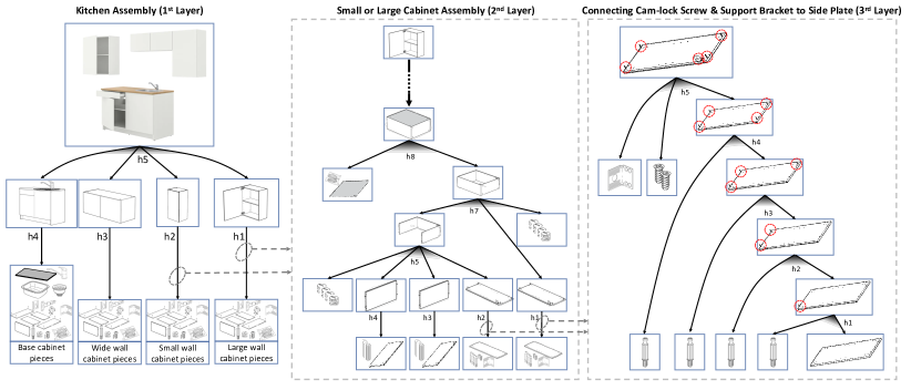
Algorithm 6 finds first feasible nodes part of an optimal cooperation path (lines 2-12), as well as the associated cost and graph. A similar operation is done in lines 13-32 for hyper-arcs. In this case it is necessary to check whether a transition exists towards a deeper AND/OR graph. If this is not the case, the hyper-arc is stored as a suggestion. Otherwise, the associated graph is determined and the function is recursively called on it. Finally, the minimum cost from the parent node of a hyper-arc to the root node of the corresponding graph is computed in line 27, and the suggestion updated accordingly. Figure 4 provides an example of a hierarchical AND/OR graph for a kitchen assembly scenario. On the left hand side, the first layer includes nodes, with the root node being on top, and hyper-arcs. Hyper-arcs and can be further specialised as second layer graphs, e.g., the one in the mid of the Figure. This is characterised by nodes and hyper-arcs (partly depicted in the Figure), two of which are further specialised as a third layer on the right.
V Reasoning on the Cooperation Model
All reasoning tasks on the cooperation model are carried out within the Task Manager module. The module receives the sets of feasible states or hyper-arcs from the Task Representation module, and determines the sequence of actions for each hyper-arc (or the sequence of processes for states), it grounds relevant parameters to actions, and allocates actions to human operators or robots to maximise a utility indicator.
V-A Reasoning upon First Order Logic based AND/OR Graphs
Differently from what happens in standard AND/OR graphs, FlexHRC+ encodes actions in hyper-arcs using a notation compliant to the Planning Domain Definition Language (PDDL) formalism [29]. In FlexHRC+, an action contributes to a transition modelled as a hyper-arc (3). To do so, it acts on a set of parameters to anchor, and it maps a set of precondition literals in conjunction (possibly defining cooperation states) to a set of effect literals, which are part of other cooperation states in the graph or are intermediate literals. The set of effect literals can be split into two disjoint sets, namely a set of literals holding true after the action has been executed, and a set of literals not holding anymore after the action. Therefore, an action in FlexHRC+ can be defined as:
| (20) |
Each action is associated with a set enumerating the agents (either human operators or robots), which may be responsible for performing . It is noteworthy that such a set may be a singleton (e.g., when only one agent can be allocated to the action), may define a set of possibilities (e.g., when a human operator or a robot may be tasked with the same action), or may define a list of agents which may be required to perform the action jointly. Using such a formalisation, although the semantics associated with the literals is known, they may not be anchored to any real object in the robot workspace at the modelling level.
Using the sequences of the actions for all the feasible states and hyper-arcs with their associated costs, Task Manager creates a data structure called Action-State table [16]. The table keeps the information of the chosen state to follow and the progress of the associated action executions. Given the Action-State table, the Task Manager either proactively selects which hyper-arc to follow, or adapts to human preferences as soon as their actions are duly recognised. In both cases, in order to reach the goal node in the graph, it identifies a cooperation path to follow with the minimum cost according to (9). Once the Task Manager selects a feasible hyper-arc that is part of the minimum cost path, to perform each action associated with the hyper-arc, FlexHRC+ must anchor non-grounded literals in action definitions, and allocate agents to each action. To do so, first updated information about the workspace is retrieved online from the Knowledge Base module. Then, all the possible literal groundings are determined, as well as all the possible combinations of agents, which may be tasked with the set of ordered actions associated with the selected hyper-arc. Using such information, a decision tree is automatically generated [17], whose various branches are related to the diverse parameter groundings and agents who can perform the actions. All branches in the tree are ranked using a utility function, i.e., a metric to estimate performance and quality of actions execution [40]. The value is generated using the utility function for each leaf of the decision tree, by simulating all the ordered set of actions associated with the selected hyper-arc, varying action parameters or assigned agents.
In general terms, a utility function to determine the best course of action for a cooperation model can be defined as the weighted sum of several robot-centred or human-centred metrics, e.g., the closest simulated distance to obstacles, the maximum joint accelerations, the maximum velocities, the overall execution time, which can be used to evaluate the overall execution quality. In our work, we have opted to consider only the execution time. Hence, given a utility function and a branch of the decision tree, the utility function is defined as to maximise the inverse of the total execution time associated with the branch , namely:
| (21) |
where is the number of actions of the selected hyper-arc or branch, is the execution time of the -th action in the branch , and the unit function equals to one if all actions in are executed successfully, to zero otherwise. A simulation is successful if the agent can reach its given goal in a defined time interval. We ground the parameters of the optimal state and assign the actions to an agent based on the branch with the maximum utility value. If the utility value of all the branches in the decision tree becomes zero, the Task Manager sets the optimal state as infeasible and attempts for a new optimal state. With this method, the Task Manager proactively avoids cooperation from failing and increases the overall robustness of the architecture. Action success or failure, and – in case of success – the time it takes to complete an action is determined by the Simulator module, which mimics the robot kinematic behaviour using the currently available knowledge of the robot state and its workspace. If disturbances are limited and the robot model is known with sufficient precision, the likelihood of having consistent results in simulation and with the real robot is increased. One may decide to simulate the robot dynamics, but in our experience this option, depending on the given task, may not provide more detailed information to compute the utility value because of uncertainties in the interaction with the environment.
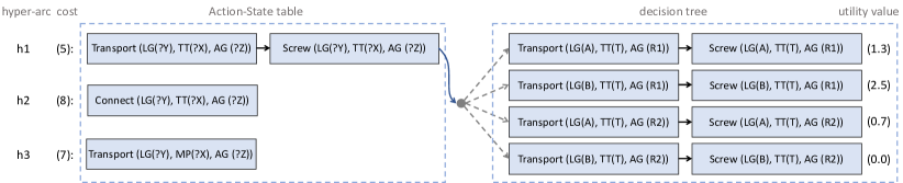
As an example, let us consider a table assembly task where a tabletop must be connected to either leg or , as shown in Figure 2. The example will be further explored in Section VI. The task can be performed by a human operator or either robot or , interchangeably. When the Task Manager receives the set of feasible hyper-arcs and their associated costs from the Task Representation module, it generates the corresponding Action-State table. Each row of the Action-State table shows the sequence of atomic actions to be carried out in the given state or hyper-arc. In the example shown in the Figure, the cooperation cost of hyper-arc is the lowest (with a value of ) among the three feasible hyper-arcs , , and . Therefore, Task Manager selects as the optimal state, and generates the corresponding decision tree (on the right hand side of the Figure). Using the information stored in the knowledge base, the predicate Tabletop(?x) can be grounded to only, and Leg(?y) can be grounded to one among or , whereas Agent(?z) can be assigned to either or . In this case, the decision tree ramifies to four branches in total. Task Manager computes the utility value by simulating all the actions in each branch, and the one with maximum utility, i.e., the second branch with , is selected to ground the parameters (leg and tabletop ) and responsible agents (robot ) of the set of actions associated with the given hyper-arc. Grounding the literals online according to the perceived information of the workspace allows the architecture to adapt to task-level variations, therefore enforcing flexibility. If, during an actual cooperation process, a human operator attempts to achieve a different feasible state, e.g., , then the Task Manager adapts to such a decision and grounds the predicates accordingly. Moreover, if the robot cannot perform a given action in a certain amount of time despite a successful simulation, assuming in , then the Task Manager stops the robot from executing its current task, sets the optimal hyper-arc to follow as infeasible, and finds a new optimal hyper-arc among the available ones, making the system more robust to failures and to environment uncertainties. However, if the execution of all the hyper-arcs fails, the collaboration as a whole fails.
It is noteworthy that a discussion of formal properties could be relevant for (i) the traversal procedure associated with the AND/OR graph, and (ii) the decision tree. In the first case, formal properties have been demonstrated by Nguyen and Szalas [57] related to AND/OR graphs when used as context-free semi-Thue systems, as in our case, including succinctness, correctness and completeness. In the second case, the decision tree is generated to model different assignments to variables, and as such is akin to brute force, although encoded in a compact representation.
V-B Behaviour of the Task Manager
The Task Manager is organised in two phases, respectively offline and online. Offline, the Task Manager initialises the list of agents participating in the collaboration scenario, all action descriptions, and the possible robots or humans who can perform each action. An action may be executed by different agents individually, or jointly. However, action assignment is done online, and the necessary skill to perform each robot action is instructed in Robot Execution Manager or the Controller. Then, the Task Manager loads the set of action sequences for all states or hyper-arcs involved in the cooperation process. Using such information, we create the necessary data structures for the online execution.
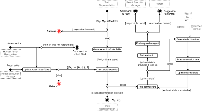
Figure 3 shows a flowchart associated with the online phase. The phase starts with an empty query from the Task Representation module. When the response to such a query is available, together with the set of feasible states or state transitions, the Task Manager first checks whether the cooperation graph is successfully solved. Otherwise, it generates the Action-State table as described above and checks for a met state or a solved state transition in the Check state execution function. Afterwards, among all feasible states, it finds the optimal state using the function Find optimal state, and checks if the actions in such a state are grounded or assigned, as well as whether the robot can successfully execute the actions in the simulation. In order to ground the optimal state action parameters and to assign actions to agents, the Task Manager first generates the decision tree in Generate decision tree, then it simulates all the actions associated with its branches using a breadth-first search algorithm, and then it computes the utility value for all the branches in Evaluate decision tree. Finally, using the function Update optimal state, it checks for the maximum utility value, it grounds all action parameters, and assigns the actions to the agents in the optimal state. If the maximum utility value is zero, the function Update optimal state sets the current optimal state as infeasible. In this case, Find optimal state selects another state with minimum cost among others available in the Action-State table, and again loops in-between simulation and decision tree evaluation. Eventually, Find next action finds the first action in the grounded or evaluated optimal state that is not done yet, and Find responsible agent is called to assign the command to an agent.
When the acknowledgement of an action execution is available (either successful or failed), the Update Action-State table function updates the representation in the Action-State table. If a human operator performs an action that was not suggested, then the Task Manager commands the robot to terminate its current action and to go to its resting configuration. Finally, if the Action-State table does not hold any feasible states or state transitions, the cooperation is failed.
VI Experimental Evaluation
VI-A Implementation and Experiments
FlexHRC+ has been validated using a dual-arm Baxter manipulator, equipped with an additional RGB-D device located on the robot’s head, and pointing downward to a table where objects to manipulate are located. In order to gather information about the motion of human operators, we use an LG G watch R (W110) smartwatch for acquiring inertial data from their right wrist. Data are routed via a Bluetooth connection to an LG G3 smartphone, and then to a workstation through standard WiFi. The workstation has an Intel Core i7-4790 3.60 GHz 8 CPUs, and 16 GB of RAM. It runs an Ubuntu 14.04 LTS 64 bit operating system. The architecture has been developed in C++/Python under the ROS Indigo framework, while the smartphone and smartwatch apps have been developed in Java.
Three types of experiments have been performed: (i) assembly operations whereby each action is carried out by the robot or the human operator, to show how the FOL-based representation outperforms standard AND/OR graphs, and the hierarchical AND/OR graph surpasses the single layer counterpart; (ii) assembly operations carried out by the robot alone to show the scalability features of the Task Representation module and to compare the benefits of the hierarchical AND/OR graph structure in real-world scenarios; (iii) cooperative assembly operations to show the flexibility, the proactive decision making and the reactive adaptation capabilities of FlexHRC+. The AND/OR graph representation is accompanied by an open source implementation111Web: https://github.com/TheEngineRoom-UniGe/ANDOR..
VI-B Performance Evaluation of the Task Representation Module
In order to carry out a performance evaluation of standard, FOL-based, and hierarchical AND/OR graph representations, let us consider the problem of assembling a table with a different number of legs, whereby we gradually increase the number of table legs to be assembled from one to nine. This implicitly makes the graph more complex due to the increasing number of required hyper-arcs. Figure 5 shows the hierarchical (on the left) and the standard version of the AND/OR graph (on the right) for a table assembly with only two legs. The task is obviously unrealistic, but it can be used to highlight the difference between the single-layer and the hierarchical representations, as well as standard and FOL-based models. The hierarchical representation is modelled by a FOL-based representation. For this task, we use a two-layer hierarchical AND/OR graph.
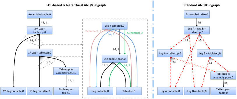
In order to connect a leg to the tabletop according to Figure 5 in the middle, there are four cooperation paths that can be followed: (i) the robot connects the leg and the tabletop directly (blue path in the Figure, cost set to ); (ii) the human operator connects the leg and the tabletop directly (red path, cost equal to ); (iii) the robot places the leg in a new position in the workspace, and later connects the leg to the tabletop (black path, cost set to ); (iv) when the leg is in a new position, the human operator connects it to the tabletop (green path, cost equal to ). In the third case, the reason for introducing a temporary new position for the table leg is that, when a dual-arm robot is used, there might be situations whereby one arm can reach the initial leg position, but only the other one can move it to its final position. Although the cost of the red and green paths are equal (both of them are ), if the robot can perform hyper-arc h1, it follows the green path. In such a path, the first feasible hyper-arc h1 is common to the black and green paths. Therefore, solving this hyper-arc can lead the cooperation to move to the black path, which is characterised by a lower cost (equal to ), as well as to the green path. Before solving the Leg middle pose node, the robot cannot ascertain whether it can perform hyper-arc h2 or not, and therefore the green path is followed if possible. While the cooperation process unfolds, human operators can switch the cooperation to the red path if they deem it fit.
In order to compare standard and FOL-based AND/OR graph representations, let us label the identical legs with and . Even if the objects are identical, their locations in the robot workspace are different. Therefore, during execution, the predicate Leg(?x) should be grounded to either or , so that the leg’s location is known to the robot when issuing motion commands. However, at the representation level, since the legs are identical, the one actually chosen is irrelevant. Figure 5 on the right hand side shows abstractly all the possible ways to place the two legs on the tabletop when they are grounded in the Task Representation module. For the sake of clarity, a simplified AND/OR graph is shown in this Figure. In the experiments, all the details (similar to what is depicted in Figure 5 in the middle) are modelled in the same layer.
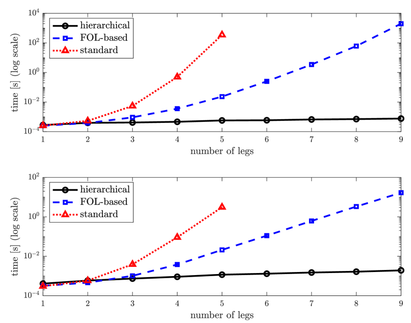
Figure 6 depicts the average computational time (in a logarithmic scale) for the table assembly task in the offline (on the top in the Figure) and online (bottom) phases. For each number of considered legs, we have performed the task ten times and we report average timings. In this experiment, the selection of the cooperation path is done randomly to avoid bias. As it can be noted, the single-layer AND/OR graph representations, i.e., the standard and the FOL-based graphs, seem to be characterised by an exponential complexity in the number of legs (both offline and online), whereas in the hierarchical representation the computational time grows linearly. In the FOL-based, single-layer representation, the average computational time increases from (one leg) to (nine legs) for the offline phase, and from to for the online phase. In the FOL-based hierarchical case, the average computational time for the offline phase increases from (one leg) to (nine legs), and for the online phase it raises from to . As demonstrated in Figure 6, the FOL-based representation outperforms the standard AND/OR graph, in terms of computational time for both the offline and online phases. The offline phase takes to solve the standard AND/OR graph with five legs, and for the equivalent FOL-based graph. For the online phase, the computational time for the standard AND/OR graph is , whereas for the FOL-based AND/OR graph is , i.e., a high advantage is given in terms of average time. The computational times in case of the single leg case are similar for FOL-based and standard AND/OR graph.
It can be observed, as also shown in Figure 5, that in principle the hierarchical AND/OR graph representation should allow designers to easily represent a table assembly task with a varying number of legs without the need for detailing which specific leg a robot or a human operator should connect to the tabletop. This is characterised by an obvious advantage in terms of representation scalability for increasingly more complex tasks. In practice, the designer of this particular cooperation process has specified nodes and hyper-arcs to model the table assembly with nine legs employing a hierarchical representation, whereas in case of FOL-based representation, nodes and hyper-arcs have been identified. Similarly, to compare standard and FOL-based AND/OR graphs, the table assembly with five legs needs and nodes, and and hyper-arcs, respectively. Clearly, it is not doable in practice to model the assemblage of a table with a high number of legs in case of a standard AND/OR graph because of the modelling complexity. Therefore, we can reasonably argue that the adoption of a FOL-based and hierarchical AND/OR graph facilitates to a great extent the modelling process. Obviously, such an evaluation should be carried by means of a methodological and experimental study, which for its extensive nature is out of scope here.
VI-C An IKEA Kitchen Assembly Scenario
Figure 4 shows the hierarchical AND/OR graph task representation realization for an IKEA kitchen composed of two wall cabinets (small and large), one wide wall cabinet, and a base cabinet with a sink and a faucet. The AND/OR graph is implemented according to the assembly documentation of the products provided on the IKEA website [58]. In this experiment, we benefit from a hierarchical AND/OR graph with five layers, however, only three layers are shown in Figure 4. The interested reader can find the complete AND/OR model in the GitHub repository associated with the developed software architecture. The kitchen assembly is comprised of pieces and connectors (such as screws and nuts, but excluding the nails) in total, assembled by distinct AND/OR graphs used in different layers, spawning nodes and hyper-arcs online. Exploiting the hierarchical representation, the designer has defined a lower number of nodes and hyper-arcs in the modelling process, i.e., nodes and hyper-arcs. Over ten trials, and by solving hyper-arcs and nodes randomly, the offline and online average computational times are and , respectively.
While designing the associated AND/OR graph, we assume that the agents assembling the kitchen can perform the following actions, namely: keeping a piece, approaching a desired pose, transporting an object to a desired pose, fitting a piece to another piece, screwing using bolt and nuts, hammering nails, following a trajectory with the contact force, grasping, and ungrasping. Moreover, the agents should perceive their own actions as well as actions by other agents, recognize the pieces and their features such as the size.
The first layer of the AND/OR graph, as represented in Figure 4 on the left hand side, decomposes the kitchen assembly task into assembly scenarios for different cabinets. The assembly of each cabinet is modelled in more detail in lower-level AND/OR graphs, therefore increasing the modularity and scalability at the representation level. The three cabinets to be attached to the wall are simpler than the base cabinet, therefore their assemblies are modelled by two additional lower-level layers, whereas the base cabinet assembly (including faucet, sink, strainer, and a drawer) is more complex, and therefore it has been modelled by four extra layers. In this scenario, the large and small wall cabinets (hyper-arcs h1 and h2 of the first-layer AND/OR graph) are similar in shape and are different in size. Owing to the FOL-based AND/OR graph representation, we can model the assembly of the two cabinets using a unique AND/OR graph. As shown in the middle of Figure 4 related to the wall cabinet assembly process, hyper-arcs h1, h2, h3, and h4 model the connection of different screws, support brackets, or dowels to the cabinet’s wooden plank parts. Hyper-arcs h5 and h6 model the connection of different planks using cam-lock nuts for constructing the structure of the cabinet. Hyper-arc h8 hammers the backplate of the cabinet to the cabinet structure using nails. Later, the assembly proceeds with fixing the hinges to the structure and front door, attaching the structure to the wall, and connecting the front door to the structure. Finally, the right hand side of Figure 4 details the hyper-arcs h1 and h2 of the cabinet assembly. It models the connection of the cam-lock screws and bracket supports to the cabinet side wooden planks. Accordingly, the Task Manager specifies the actions to carry out in order to execute hyper-arcs.
The IKEA kitchen assembly scenario demonstrates the scalability feature of AND/OR graphs with several layers, i.e., the possibility to define layers of different semantics, and to exploit the same lower-level assembly scenario in several higher-level assembly processes. Although this representation model is here presented only as it is, i.e., we do not show a real robot actually collaborating with a human operator in the process, nonetheless we believe it is a good example of a real-world, yet complex assembly process, which could be an excellent use case.
VI-D A Human-Robot Cooperative Table Assembly Task
In a third set of tests, a number of human-robot cooperative table assembly tasks have been carried out using tables different in terms of tabletop sizes and leg lengths, without any change at the task representation level.
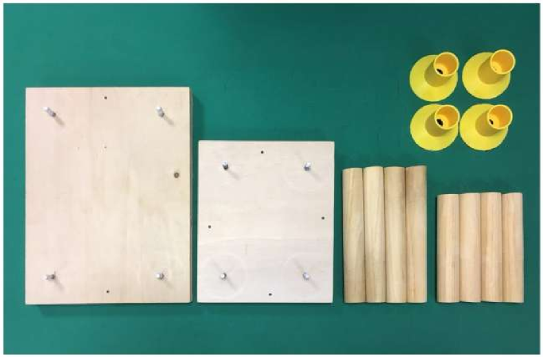
These tests demonstrate FlexHRC+ capabilities at two levels. On the one hand, at the team level, the human operator and the robot perform the same table assembly task using different cooperation paths online, including no cooperation at all, i.e., the operator or the robot manage the assembly process on their own. On the other hand, at the task level, the human operator and the robot can cooperate on similar tasks, such as the assembly of tables with different physical properties, without the need for ad hoc representations. In particular, we have used two rectangular tabletops, two sets of four legs, and four customised 3D printed skirts to guide the legs when placing them into the screws for precision compensation, and also to fix the legs to the tabletop, all of them shown in Figure 7. Hence, four different types of tables can be assembled, which are not a priori known to the human operator nor the robot. Initially, the legs and the tabletop are randomly located in the shared human-robot workspace.
Modelled human operator actions include pick up (the human operator picks up one of the legs for manipulation purposes), put down (the manipulated object is put on the table in front of the robot), and screw (the human operator fixes the leg to the tabletop using a rotation movement), whereas robot actions include approach (the robot approaches the grasping pose of an object with one of its end-effectors), transport (the robot moves an object to a desired goal position on the table) screw (similar to the one to be executed by human operators), unscrew (the robot counter-rotates a leg with respect to the screw action), grasp (the robot closes one of its grippers after approaching an object), ungrasp (the robot opens a gripper), and update workspace (the robot updates its internal representation of the workspace using perception modules).
We model the cooperative table assembly task with four legs using a single-layer FOL-based AND/OR graph similar to the one shown in Figure 5. The AND/OR graph representation encompasses all the possibilities, ranging from the case whereby either the human operator or the robot assemble the whole table on their own, to various cases in which the operator and the robot cooperate.
The table assembly task has been performed eight times as presented in the accompanying video222Web: https://youtu.be/CEIARyW422o.. Results are summarised in Table I. The Table shows that the overall execution of Task Manager, Task Representation, and Simulator require less than of the complete table assembly task, with a low standard deviation. The more time consuming portions of the cooperation are the actions performed by the human operator or the robot. The high standard deviation associated with experiment lengths is mainly due to human decisions taken online, and to the significant difference between the human and robot speeds in performing the actions. As a reference, the maximum robot joint angular velocity, and end-effector angular and linear velocities are , , and , respectively.
| Computation | avg time [s] | avg time [%] | std [s] |
|---|---|---|---|
| Task Manager | 0.01 | 0.00 | 0.00 |
| Task Representation | 0.57 | 0.23 | 0.01 |
| Simulator | 4.15 | 1.66 | 0.40 |
| Robot actions | 219.45 | 87.75 | 56.90 |
| Human actions | 25.82 | 10.32 | 5.67 |
| Total | 250.09 | 100.00 | 51.87 |
To avoid repetitions in showing the results for different parts of the experiments, we divide the cooperative table assembly task in three segments: in the first (tabletop placement), the robot places the tabletop in the workspace; the second segment (legs fix) is related to all operations to fix the legs to the tabletop; in the last segment (check) the human operator checks all connections.
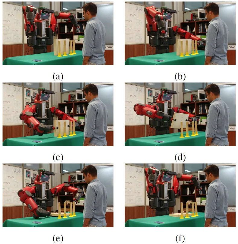
Figure 8 shows an example of tabletop placement. In our experiments, this sequence is always carried out by the robot: the robot’s left and right arms approach the tabletop (a-b), grasp it (c), change its orientation and place it on the table horizontally (d-e), and finally return to the resting pose (f).
Figures 9, 10, 11, 12 show different situations whereby the human operator and the robot perform a legs fix cooperatively. They are free to choose which leg to pick up for manipulation, whereas the order of the bolts on the tabletop is a priori defined in our scenario.
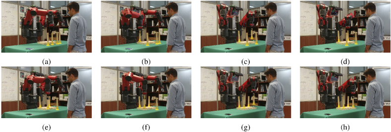
Figure 9 shows the case in which the robot connects all the legs to the tabletop. At the beginning, the robot can choose which one of the four legs to pick up, as well as which arm to use to do it. As shown in the previous Section, this is modelled using FOL-based predicates whose literals must be anchored to actual percepts. To do so, the robot evaluates the utility function for all eight options (i.e., all the couples of legs and arms) using the Simulator module. In this specific example, the second leg from the right and the right arm are selected (a-b, robot point of view). The human operator decides not to intervene in the assembly process, and the robot performs all the assembly operations autonomously. Therefore, the robot follows the blue cooperation path shown in Figure 5, and fixes all the legs to the tabletop.
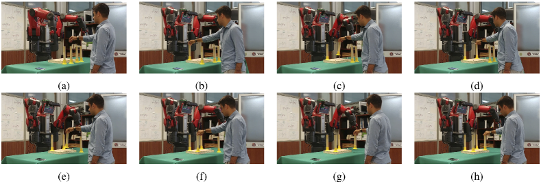
Figure 10 shows a case in which the human operator decides to connect all the legs to the tabletop. The robot tries, by default, to follow the minimum cost cooperation path (in blue in Figure 5), but as soon as the pick up action by the human operator is detected, the robot follows the corresponding cooperation path in red.
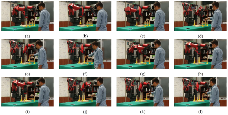
Figure 11 shows the case in which the human operator and the robot cooperate to connect all the legs to the tabletop. In particular, in (a-c) it is shown how the robot fixes the rightmost leg to the tabletop. Later, the robot decides to connect another leg with the left arm, but the human operator intervenes and performs the fix operation to the second tabletop bolt (d-f). The robot adapts to the human decision when the human action is recognised. It updates its representation of the workspace via the Object and Scene Perception module, it updates the AND/OR graph and determines the new set of feasible states. Then, the robot connects the third leg to the tabletop, and finally the human decides to fix the last leg (g-l).
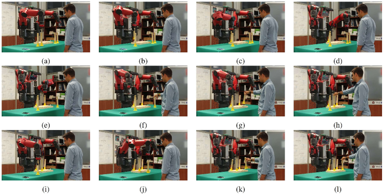
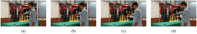
Figure 12 shows how the robot adapts to human decisions, and how it can proactively request the human to perform a certain task, which it cannot perform. In (a-e) the robot connects the first two legs to the tabletop. Afterwards, the human operator decides to connect the third leg to the tabletop (f-h). Finally, in (i-l) a situation is depicted whereby the robot is not capable of performing a given task, and therefore it asks the human operator to connect the last leg to the tabletop. By following the green cooperation path in Figure 5, first the robot transports the leg in front of the human operator, and finally the operator connects it to the tabletop.
Finally, Figure 13 shows the human operator controlling all leg connections to the tabletops at the end of the task.
It is noteworthy that in Figures 9, 10, and 12, the human operator and the robot assemble the large tabletop with the long legs, while in Figure 11 they assemble the small table with the short legs. These examples show the ability of FlexHRC+ to handle different real-world objects, i.e., anchoring different percepts to the same symbol-mediated predicates in the FOL-based representation. As a consequence, we can considered the perception layer and the representation layer as decoupled, i.e., changes in the robot workspace need not to be represented.
VI-E Discussion
As posited in the Introduction, FlexHRC+ targets three of the identified requirements for HRC, namely , which is related to the trade-off between flexibility and actions aimed at meeting the cooperation objectives, , whereby the robot should exhibit flexible decision making capabilities, and , the capability of doing so exploiting hierarchical task representation structures.
In the first case, it is posited that a control architecture for collaborative robots should not only provide the necessary autonomy for general-purpose action planning and execution, but should also allow the collaborative robot to adapt to the behaviour of human operators. Such an adaptation should be limited to the available plans reaching the cooperation goal. FlexHRC+ copes with by equipping the robot with the ability of autonomously scheduling the most appropriate actions to carry out, while exploiting perception and action modules to adapt to human operators. The hierarchical, FOL-based AND/OR graph representation is capable of switching among possible, intrinsically feasible plans, and among them following the currently optimal one. This is achieved also by means of an in-the-loop, simulation-based approach to anchor internal symbols to actual perceptions. The results of the simulation include the actions to be performed, as well as the upcoming end-effector trajectories. Although human-robot communication is not the focus of the paper, it is noteworthy that current work is devoted to the use of Augmented Reality technology to intuitively communicate upcoming robot actions to human operators [59, 60]. In the second case, FlexHRC+ enables some level of flexibility as far as the representation of the cooperative task is concerned, as required by . The framework separates low-level perception activities from the high-level structure of the cooperation task. At the task and architectural levels, the robustness to noisy or inaccurate perception is mainly related to what happens in the Knowledge base module. Therein, two assumptions are made, i.e., closed-world and continuity, which imply that any change in the robot workspace is the consequence of actions performed by the human operator or the robot. In the current version of FlexHRC+, all relevant information for robot behaviour is maintained in the knowledge base. If newly perceived information is not compatible with stored information, then the knowledge base enters an inconsistent state, and waits for new, compatible, information. In previous work [30], we have shown how to deal with inconsistent states in a knowledge base, by using the notion of normative knowledge (i.e., information expected to hold at a given time instant) to plan for a series of robot actions aimed at solving inconsistencies. Such an approach is not integrated with FlexHRC+ yet. As far as is concerned, a hierarchical representation is a key enabling factor to model complex scenarios adopting a bottom-up approach and achieving lower reasoning times. In the Task Representation module, the use of hierarchical, FOL-based AND/OR graphs simplifies the definition of qualitatively similar tasks, which can be then used to model different phases of the cooperation, and it greatly increases the computational efficiency in graph traversal, which is of the utmost importance to allow collaborative robots to be reactive and adaptive to plan changes. This allows for building a library of simpler tasks, which can be composed together to create composite tasks [61]. In this respect, current work is devoted to integrate in FlexHRC+ the capability of learning from human demonstrations and through interactions with the environment [62].
VII Conclusions
In this paper, we have introduced a human-robot cooperation framework enabling a greater flexibility and scalability in assembly tasks. In terms of flexibility, two levels are involved. At the task level, the robot deals with the differences in the objects being manipulated, without the need for explicitly encoding such differences in the cooperation model. At the cooperation level, different modules in the framework allow the human operator or the robot to choose the degree of cooperation as the task progresses. As far scalability is concerned, it is possible to design complex cooperation scenarios building upon simpler ones. To this aim, a First Order Logic hierarchical task representation has been developed and integrated within the framework. The introduced FOL-based hierarchical AND/OR graph structure makes task representation efficient enough to perform highly complex scenarios, while at the same time simplifying the design phase, and ensuring explainable robot behaviour. However, a designer is still required to manually build the graph. This implies a deep knowledge of the assembly task as well as of the involved robot capabilities. Obviously enough, such a process is time-consuming, and it is prone to modelling errors or inaccuracies.
In order to cope with these shortcomings, as mentioned in the Introduction, a must-have feature for next generation collaborative robots would be the capability of learning the task structure both at the task and the action level [63, 64, 15, 65].While at the task level a robot may learn the sequence of discrete actions [64, 66], at the action level it should learn how to control its movements to reach a given goal [15, 67]. We plan to tackle such learning aspects in a future development of FlexHRC+.
References
- [1] euRobotics aisbl, “Strategic research agenda for robotics in europe 2014–2020,” 2014, [Accessed 2018-08-04]. [Online]. Available: https://www.eu-robotics.net/cms/upload/downloads/ppp-documents/SRA2020_SPARC.pdf
- [2] B. Esmaeilian, S. Behdad, and B. Wang, “The evolution and future of manufacturing: A review,” Journal of Manufacturing Systems, vol. 39, pp. 79–100, 2016.
- [3] S. Kock, T. Vittor, B. Matthias, H. Jerregard, M. Källman, I. Lundberg, R. Mellander, and M. Hedelind, “Robot concept for scalable, flexible assembly automation: A technology study on a harmless dual-armed robot,” in Proceedings of the 2011 IEEE International Symposium on Assembly and Manufacturing (ISAM), Tampere, Finland, May 2011.
- [4] euRobotics aisbl, European Robotics Association, and European Commission , “Robotics 2020 multi-annual roadmap for robotics in europe, horizon 2020 call ict-2017,” 2017, [Accessed 2018-08-04, Release B, 02/12/2016]. [Online]. Available: https://www.eu-robotics.net/cms/upload/topic_groups/H2020_Robotics_Multi-Annual_Roadmap_ICT-2017B.pdf
- [5] International Federation of Robotics, “Robots and the workplace of the future,” March 2018, [Accessed 2018-08-04, positioning paper]. [Online]. Available: https://ifr.org/downloads/papers/IFR_Robots_and_the_Workplace_of_the_Future_Positioning_Paper.pdf
- [6] A. Cherubini, R. Passama, A. Crosnier, A. Lasnier, and P. Fraisse, “Collaborative manufacturing with physical human-robot interaction,” Robotics and Computer-Integrated Manufacturing, vol. 40, pp. 1–13, 2016.
- [7] J. A. Adams, “Human-robot interaction design: Understanding user needs and requirements,” in Proceedings of the 2005 Annual Meeting on Human Factors and Ergonomics Society (HFES), vol. 49, no. 3, Orlando, FL, USA, September 2005.
- [8] A. Steinfeld, T. Fong, D. Kaber, M. Lewis, J. Scholtz, A. Schultz, and M. Goodrich, “Common metrics for human-robot interaction,” in Proceedings of the 2006 ACM SIGCHI/SIGART Conference on Human-robot Interaction (HRI), Salt Lake City, Utah, USA, March 2006.
- [9] D. Bortot, M. Born, and K. Bengler, “Directly or on detours? how should industrial robots approximate humans?” in Proceedings of the 2013 ACM/IEEE International Conference on Human-Robot Interaction (HRI), Tokyo, Japan, March 2013.
- [10] A. DeSantis, B. Siciliano, A. DeLuca, and A. Bicchi, “An atlas of physical human-robot interaction,” Mechanism and Machine Theory, vol. 43, no. 3, pp. 253–270, 2008.
- [11] P. A. Lasota, T. Fong, and J. A. Shah, “A survey of methods for safe human-robot interaction,” Foundations and Trends® in Robotics, vol. 5, no. 4, pp. 261–349, 2017.
- [12] M. A. Goodrich and A. C. Schultz, “Human-robot interaction: a survey,” Foundations and Trends® in Human–Computer Interaction, vol. 1, no. 3, pp. 203–275, 2007.
- [13] F. Ferland, D. Létourneau, A. Aumont, J. Frémy, M.-A. Legault, M. Lauria, and F. Michaud, “Natural interaction design of a humanoid robot,” Journal of Human-Robot Interaction, vol. 1, no. 2, pp. 118–134, 2013.
- [14] A. Valli, “The design of natural interaction,” Multimedia Tools and Applications, vol. 38, no. 3, pp. 295–305, 2008.
- [15] B. D. Argall, S. Chernova, M. Veloso, and B. Browning, “A survey of robot learning from demonstration,” Robotics and Autonomous Systems, vol. 57, no. 5, pp. 469–483, 2009.
- [16] K. Darvish, F. Wanderlingh, B. Bruno, E. Simetti, F. Mastrogiovanni, and G. Casalino, “Flexible human-robot cooperation models for assisted shop-floor tasks,” Mechatronics, vol. 51, pp. 97–114, 2018.
- [17] K. Darvish, B. Bruno, E. Simetti, F. Mastrogiovanni, and G. Casalino, “Interleaved online task planning, simulation, task allocation and motion control for flexible human-robot cooperation,” in Proceedings of the 2018 IEEE International Symposium on Robot and Human Interactive Communication (RO-MAN), Nanjing and Tai’an, China, August 2018.
- [18] P. García, P. Caamaño, R. J. Duro, and F. Bellas, “Scalable task assignment for heterogeneous multi-robot teams,” International Journal of Advanced Robotic Systems, vol. 10, no. 2, p. 105, 2013.
- [19] J. Shah, J. Wiken, B. Williams, and C. Breazeal, “Improved human-robot team performance using Chaski, a human-inspired plan execution system,” in Proceedings of the 2011 ACM/IEEE International Conference on Human-Robot Interaction (HRI), Switzerland, March 2011.
- [20] S. Lemaignan, M. Warnier, E. A. Sisbot, A. Clodic, and R. Alami, “Artificial cognition for social human–robot interaction: An implementation,” Artificial Intelligence, vol. 247, pp. 45–69, 2017.
- [21] J. W. Crandall, M. Oudah, T. Chenlinangjia, F. Ishowo-Oloko, S. Abdallah, J. Bonnefon, M. Cebrián, A. Shariff, M. A. Goodrich, and I. Rahwan, “Cooperating with machines,” Nature Communications, vol. 9, no. 1, p. 233, 2018.
- [22] L. Johannsmeier and S. Haddadin, “A hierarchical human-robot interaction-planning framework for task allocation in collaborative industrial assembly processes,” IEEE Robotics and Automation Letters, vol. 2, no. 1, pp. 41–48, January 2017.
- [23] E. Lamon, A. De Franco, L. Peternel, and A. Ajoudani, “A capability-aware role allocation approach to industrial assembly tasks,” IEEE Robotics and Automation Letters, vol. 4, no. 4, pp. 3378–3385, 2019.
- [24] S. J. Levine and B. C. Williams, “Concurrent plan recognition and execution for human-robot teams.” in Proceedings of the 2014 International Conference on Automated Planning and Scheduling (ICAPS), Portsmouth, NH, USA, June 2014.
- [25] K. P. Hawkins, S. Bansal, N. N. Vo, and A. F. Bobick, “Anticipating human actions for collaboration in the presence of task and sensor uncertainty,” in Proceedings of the 2014 IEEE International Conference on Robotics and Automation (ICRA), Hong Kong, China, May 2014.
- [26] S. Nikolaidis, D. Hsu, and S. Srinivasa, “Human-robot mutual adaptation in collaborative tasks: Models and experiments,” The International Journal of Robotics Research, vol. 36, no. 5-7, pp. 618–634, 2017.
- [27] M. Toussaint, T. Munzer, Y. Mollard, L. Y. Wu, N. A. Vien, and M. Lopes, “Relational activity processes for modeling concurrent cooperation,” in Proceedings of the 2016 IEEE International Conference on Robotics and Automation (ICRA), Stockholm, Sweden, May 2016.
- [28] D. Claes and K. Tuyls, “Human robot-team interaction,” in Proceedings of the 2013 International Symposium on Artificial Life and Intelligent Agents (ALIA), Bangor, Wales, UK, 2014.
- [29] M. Cashmore, M. Fox, D. Long, D. Magazzeni, B. Ridder, A. Carrera, N. Palomeras, N. Hurtos, and M. Carreras, “Rosplan: Planning in the robot operating system.” in Proceedings of the 2015 International Conference on Automated Planning and Scheduling (ICAPS), Jerusalem, Israel, June 2015.
- [30] A. Capitanelli, M. Maratea, F. Mastrogiovanni, and M. Vallati, “On the manipulation of articulated objects in human-robot cooperation scenarios,” CoRR, vol. abs/1801.01757, 2018.
- [31] S. Russell and P. Norvig, Artificial Intelligence: A Modern Approach, 3rd ed. Upper Saddle River, NJ, USA: Prentice Hall Press, 2010.
- [32] R. Caccavale, J. Cacace, M. Fiore, R. Alami, and A. Finzi, “Attentional supervision of human-robot collaborative plans,” in Proceedings of the 2016 IEEE International Symposium on Robot and Human Interactive Communication (RO-MAN), New York City, NY, USA, August 2016.
- [33] C. Paxton, A. Hundt, F. Jonathan, K. Guerin, and G. D. Hager, “Costar: Instructing collaborative robots with behavior trees and vision,” in 2017 IEEE international conference on robotics and automation (ICRA). IEEE, 2017, pp. 564–571.
- [34] R. Wilcox, S. Nikolaidis, and J. Shah, “Optimization of temporal dynamics for adaptive human-robot interaction in assembly manufacturing,” in Proceedings of the 2012 Robotics: Science and Systems, Sydney, Australia, July 2012.
- [35] P. Tsarouchi, G. Michalos, S. Makris, T. Athanasatos, K. Dimoulas, and G. Chryssolouris, “On a human–robot workplace design and task allocation system,” International Journal of Computer Integrated Manufacturing, vol. 30, no. 12, pp. 1272–1279, 2017.
- [36] R. Caccavale and A. Finzi, “Flexible task execution and attentional regulations in human-robot interaction,” IEEE Transactions on Cognitive and Developmental Systems, vol. 9, no. 1, pp. 68–79, 2017.
- [37] E. Sebastiani, R. Lallement, R. Alami, and L. Iocchi, “Dealing with on-line human-robot negotiations in hierarchical agent-based task planner,” in Proceedings of 2017 International Conference on Automated Planning and Scheduling (ICAPS), Pittsburgh, PA, USA, June 2017.
- [38] N. Miyata, J. Ota, T. Arai, and H. Asama, “Cooperative transport by multiple mobile robots in unknown static environments associated with real-time task assignment,” IEEE Transactions on Robotics and Automation, vol. 18, no. 5, pp. 769–780, 2002.
- [39] F. Chen, K. Sekiyama, F. Cannella, and T. Fukuda, “Optimal subtask allocation for human and robot collaboration within hybrid assembly system,” IEEE Transactions on Automation Science and Engineering, vol. 11, no. 4, pp. 1065–1075, 2014.
- [40] B. P. Gerkey and M. J. Matarić, “A formal analysis and taxonomy of task allocation in multi-robot systems,” The International Journal of Robotics Research, vol. 23, no. 9, pp. 939–954, 2004.
- [41] J. A. Shah, P. R. Conrad, and B. C. Williams, “Fast distributed multi-agent plan execution with dynamic task assignment and scheduling,” in Proceedings of the 2009 International Conference on Automated Planning and Scheduling (ICAPS), September 2009.
- [42] T. R. A. Giele, T. Mioch, M. A. Neerincx, and J.-J. C. Meyer, “Dynamic task allocation for human-robot teams,” in Proceedings of the 2015 International Conference on Agents and Artificial Intelligence (ICAART), Lisbon, Portugal, January 2015.
- [43] H. S. Koppula and A. Saxena, “Anticipating human activities for reactive robotic response,” in Proceedings of the 2013 IEEE/RSJ International Conference on Intelligent Robots and Systems (IROS), Tokyo, Japan, November 2013.
- [44] J. Mainprice, R. Hayne, and D. Berenson, “Predicting human reaching motion in collaborative tasks using inverse optimal control and iterative re-planning,” in Proceedings of the 2015 IEEE International Conference on Robotics and Automation (ICRA), Seattle, WA, USA, May 2015.
- [45] L. S. H. de Mello and A. C. Sanderson, “And/or graph representation of assembly plans,” IEEE Transactions on Robotics and Automation, vol. 6, no. 2, pp. 188–199, 1990.
- [46] B. Bruno, F. Mastrogiovanni, A. Sgorbissa, T. Vernazza, and R. Zaccaria, “Analysis of human behavior recognition algorithms based on acceleration data,” in Proceedings of the 2013 IEEE International Conference on Robotics and Automation (ICRA), Karlsruhe, Germany, May 2013.
- [47] B. Bruno, F. Mastrogiovanni, A. Saffiotti, and A. Sgorbissa, “Using fuzzy logic to enhance classification of human motion primitives,” in Information Processing and Management of Uncertainty in Knowledge-Based Systems, A. Laurent, O. Strauss, B. Bouchon-Meunier, and R. R. Yager, Eds. Montpellier, France: Springer International Publishing, 2014, pp. 596–605.
- [48] M. A. Fischler and R. C. Bolles, “Random sample consensus: a paradigm for model fitting with applications to image analysis and automated cartography,” Communications of the ACM, vol. 24, no. 6, pp. 381–395, 1981.
- [49] S. Wold, K. Esbensen, and P. Geladi, “Principal component analysis,” Chemometrics and Intelligent Laboratory Systems, vol. 2, no. 1-3, pp. 37–52, 1987.
- [50] L. Buoncompagni and F. Mastrogiovanni, “A software architecture for object perception and semantic representation,” in Proceedings of the 2015 Italian Workshop on Artificial Intelligence and Robotics (AIRO), Ferrara, Italy, September 2015.
- [51] E. Simetti and G. Casalino, “A novel practical technique to integrate inequality control objectives and task transitions in priority based control,” Journal of Intelligent & Robotic Systems, vol. 84, no. 1, pp. 877–902, 2016.
- [52] E. Simetti, G. Casalino, F. Wanderlingh, and M. Aicardi, “Task priority control of underwater intervention systems: Theory and applications,” Ocean Engineering, vol. 164, pp. 40 – 54, 2018.
- [53] G. F. Luger, Artificial Intelligence: Structures and Strategies for Complex Problem Solving, 6th ed. Boston, MA, USA: Addison-Wesley Publishing Company, 2009.
- [54] L. Buoncompagni and F. Mastrogiovanni, “Dialogue-based supervision and explanation of robot spatial beliefs: a software architecture perspective,” in Proceedings of the 2018 IEEE International Symposium on Robot and Human Interactive Communication (RO-MAN), Nanjing and Tai’an, China, August 2018.
- [55] E. Laber, “A randomized competitive algorithm for evaluating priced and/or trees,” Theorical Computer Science, vol. 1, no. 401, pp. 120–130, 2008.
- [56] S. Sahni, “Computationally related problems,” SIAM Journal on Computing, vol. 4, no. 3, pp. 262–279, 1974.
- [57] L. A. Nguyen and A. Szałas, “A tableau calculus for regular grammar logics with converse,” in Proceedings of International Conference on Automated Deduction, Montreal, Canada, August 2009, pp. 421–436.
- [58] IKEA. [Online]. Available: https://www.ikea.com
- [59] S. A. Green, J. G. Chase, X. Chen, and M. Billinghurst, “Evaluating the augmented reality human-robot collaboration system,” in Proceedings of the 2008 International Conference on Mechatronics and Machine Vision in Practice, Auckland, New Zealand, December 2008.
- [60] G. Michalos, P. Karagiannis, S. Makris, Önder Tokçalar, and G. Chryssolouris, “Augmented reality (AR) applications for supporting human-robot interactive cooperation,” Procedia CIRP, vol. 41, pp. 370–375, 2016.
- [61] F. Mastrogiovanni and A. Sgorbissa, “A behaviour sequencing and composition architecture based on ontologies for entertainment humanoid robots,” Robotics and Autonomous Systems, vol. 61, no. 2, pp. 170–183, 2013.
- [62] A. Carfì, J. Villalobos, E. Coronado, B. Bruno, and F. Mastrogiovanni, “Can human-inspired learning behaviour facilitate human-robot interaction?” International Journal of Social Robotics, To appear.
- [63] A. Stopp, S. Horstmann, S. Kristensen, and F. Lohnert, “Toward interactive learning for manufacturing assistants,” IEEE Transactions on Industrial Electronics, vol. 50, no. 4, pp. 705–707, Aug 2003.
- [64] S. Ekvall and D. Kragic, “Robot learning from demonstration: A task-level planning approach,” International Journal of Advanced Robotic Systems, vol. 5, no. 3, p. 33, 2008.
- [65] G. Konidaris, S. Kuindersma, R. Grupen, and A. Barto, “Robot learning from demonstration by constructing skill trees,” The International Journal of Robotics Research, vol. 31, no. 3, pp. 360–375, 2012.
- [66] T. Munzer, M. Toussaint, and M. Lopes, “Preference learning on the execution of collaborative human-robot tasks,” in Proceedings of the 2017 IEEE International Conference on Robotics and Automation (ICRA), May 2017.
- [67] P. Kormushev, S. Calinon, and D. G. Caldwell, “Robot motor skill coordination with em-based reinforcement learning,” in Proceedings of the 2010 IEEE/RSJ International Conference on Intelligent Robots and Systems, Taipei, Taiwan, October 2010.