Mobility of dislocations in zirconium
Abstract
Plasticity in hexagonal close-packed zirconium is mainly controlled by the glide of dislocations with Burgers vectors. As these dislocations cannot accommodate deformation in the direction, twinning or glide of \hkl¡c+a¿ dislocations, i.e. dislocations with Burgers vector, have to be activated. We have performed in situ straining experiments in a transmission electron microscope to study the glide of \hkl¡c+a¿ dislocations in two different zirconium samples, pure zirconium and Zircaloy-4, at room temperature. These experiments show that \hkl¡c+a¿ dislocations exclusively glide in first-order pyramidal planes with cross-slip being activated. A much stronger lattice friction is opposing the glide of \hkl¡c+a¿ dislocations when their orientation corresponds to the \hkl¡a¿ direction defined by the intersection of their glide plane with the basal plane. This results in long dislocations straightened along \hkl¡a¿ which glide either viscously or jerkily. This \hkl¡a¿ direction governs the motion of segments with other orientations, whose shape is merely driven by the minimization of the line tension. The friction due to solute atoms is also discussed.
keywords:
Dislocations, Plasticity, Zirconium, In situ straining experiments, Transmission electron microscopy1 Introduction
Zirconium alloys are used in the nuclear industry as fuel cladding tubes and structural components in light and heavy water reactors [1]. Like in other hexagonal close-packed (hcp) metals, plastic activity strongly varies between the different possible slip systems in zirconium. The principal slip system is controlled by glide of \hkl¡a¿ dislocations, i.e. dislocations with Burgers vectors, in the \hkl10-10 prismatic planes [2, 3]. These \hkl¡a¿ dislocations can also cross-slip above room temperatures to glide in the \hkl(0001) basal and \hkl10-11 first-order pyramidal planes [4]. However all these deformation modes only accommodate deformation along \hkl¡a¿ directions and other mechanisms, either twinning or glide of dislocations with a \hkl¡c¿ component, are needed to allow for a deformation along the axis of the hcp crystal.
Both twinning and glide of \hkl¡c+a¿ dislocations, i.e. dislocations with Burgers vectors, are active in zirconium [5, 6, 7, 8, 9, 10, 11, 12, 13, 14, 15], with slip becoming more active when the temperature increases. Depending of the hcp metals, these \hkl¡c+a¿ dislocations can glide in the first-order \hkl10-11 or second-order \hkl-2112 pyramidal planes. Almost all transmission electron microscopy (TEM) observations have shown, by slip traces analysis [7] or stereography [8, 10, 11, 13, 14, 15, 16], that \hkl¡c+a¿ dislocations glide in first-order pyramidal planes in Zr alloys, with possible cross-slip between two pyramidal planes sharing the same \hkl¡c+a¿ direction [14, 15, 16]. Scanning electron microscopy of slip traces on bended micro-cantilever well oriented to activate only \hkl¡c+a¿ slip also concluded that \hkl¡c+a¿ dislocation glide in first-order pyramidal planes, without any trace of slip in second-order pyramidal planes, both for the compressive and tensile parts of the cantilevers [17]. Only Long et al. [16] have recently evidenced that a minority of \hkl¡c+a¿ can also be found in the second order pyramidal plane in a Zr-2.5Nb alloy. Besides, some of these TEM observations indicate that \hkl¡c+a¿ dislocations have a tendency to straighten in the direction corresponding to the intersection of the pyramidal glide plane with the basal plane [8, 11, 15, 16], a feature which is not specific to zirconium and can be found in other hcp metals, like Mg [18, 19, 20, 21, 22, 23] or Ti [24, 25], regardless of the pyramidal glide plane.
The critical resolved shear stress (CRSS) necessary to activate glide of \hkl¡c+a¿ dislocations strongly depends on the temperature but is always much higher than the CRSS of \hkl¡a¿ dislocation glide [7, 17], thus explaining the strong plastic anisotropy of zirconium single crystals. An increased activity of \hkl¡c+a¿ slip is observed in irradiated zirconium alloys, as the hardening induced by irradiation defects appears stronger on \hkl¡a¿ slip systems than on \hkl¡c+a¿ pyramidal slip [14, 26], thus partly compensating for the friction difference between the two types of dislocations.
Although the mobility of \hkl¡c+a¿ dislocations is a key ingredient of the plastic anisotropy of zirconium, not much is known on this mobility besides the slip plane, the dislocation ability to cross-slip and their tendency to align in a specific direction as mentioned above. In situ TEM straining experiments are a valuable tool to study dislocation mobility. Such experiments in zirconium have already revealed some key features of \hkl¡a¿ dislocations [3, 14, 27, 28, 4, 29]. But no such in situ observations have been performed for the glide of \hkl¡c+a¿ dislocations in zirconium. The difficulty arises from the necessity to have grains well oriented to activate \hkl¡c+a¿ slip. The aim of the present article is to present such experiments. In situ TEM straining experiments have been performed in two different zirconium alloys, Zircaloy-4 and pure zirconium, as previous experimental studies on polycrystals [6] have shown a difference in the strain accommodation along the \hkl¡c¿ axis between Zircaloy-4 and pure zirconium. The results of these in situ experiments are presented below.
2 Experimental procedure
2.1 Materials
Two different zirconium materials have been chosen for this study: zirconium sponge, which is essentially pure zirconium, and Zircaloy-4 in the recrystallized metallurgical state, which is often considered as a model material for zirconium alloys. Their chemical compositions are given in Table 1.
| Sn | Fe | Cr | O | Zr | |
|---|---|---|---|---|---|
| Pure Zr | - | 0.019 | - | 0.024 | bal. |
| Zircaloy-4 | 1.32 | 0.215 | 0.108 | 0.125 | bal. |
2.1.1 Pure zirconium
Pure zirconium results from the Kroll process in the form of a 3 mm thick plate. The raw zirconium sponge has first been arc-melted and cold-rolled with intermediate recrystallization treatments during 3 hours at 580 ∘C. After the last cold-rolling step, the same recrystallization treatment has been applied followed by a tensile test up to a strain of 1.5. The purpose of this straining was to reach critical strain annealing phenomenon in order to obtain large grains [30, 31]. This straining was followed by an annealing at 840 ∘C during 24 hours. After this treatment, the mean grain size was 70 m with a large dispersion around this value. The material texture exhibited \hkl¡c¿ axis mainly along the normal direction (ND) of the plate. Small samples, 3 mm long and 1 mm wide, were taken out of the plate with the long direction along ND, to activate \hkl¡c+a¿ slip.
2.1.2 Zircaloy-4
Recrystallized Zircaloy-4 is used for light water reactor applications as guide tubes. These tubes have a thickness smaller than 1 mm and exhibit a strong texture with the \hkl¡c¿ axis of the grains close to the radial direction (RD) of the tube, in the AD-RD (AD: axial direction) plane. Such products are not suitable to study easily the activation of pyramidal \hkl¡c+a¿ slip, as one has to pull the grains along directions close to the \hkl¡c¿ axis which are mainly along the radial direction of the thin tube. Because of the small thickness of the tube along the radial direction, it is not possible to machine small tensile test samples in this direction. This is the reason why an intermediate product of the fabrication process, called TREX for Tube Reduced Extrusion, has been used. This is a thick tube, with diameter of the order of 55 mm and thickness of the order of 10 mm. This material exhibits equi-axed grains with mean size of 6 m and a low initial dislocation density, only of the order of m-2. The \hkl¡c¿ axis of the grains are mainly oriented in the RD-TD (TD: transverse direction) plane with the highest pole density along TD [32, 33]. Small dog-bone specimens, 11.5 mm long and 2.3 mm wide, were machined by electrical discharge, with the tensile direction along TD. Therefore, thanks to the texture, a large number of grains are expected to have their \hkl¡c¿ axis along the tensile direction.
2.2 In situ TEM straining experiments
Pure zirconium and Zircaloy-4 samples have been mechanically polished down to 0.1 mm thick and electropolished to make a small hole, using a mixture of 90 of ethanol and 10 of perchlorate acid at ∘C. The thin area around the hole is only few hundreds nanometer thick and is therefore suitable for TEM observations.
In situ straining experiments were performed at room temperature on both materials using a GATAN cooling and straining TEM sample holder on a JEOL 2010 operating at 200 kV. The thin foils were pasted on two ceramic rings or on copper grids at each ends to be pulled by the TEM holder. For Zircaloy-4, experiments have been also conducted at room temperature on a FEI Tecnai operating at 200 kV, using the commercial room temperature GATAN straining specimen-holder and the dog-bone TEM samples. On these two specimen holders, one cross-head of the sample is fixed and the other cross-head is attached to a bar which displacement is controlled by a motor. Typical displacements are 100 m.
The experimental procedure is as follows. First, the orientation of various grains is analyzed until finding a grain with an orientation that satisfies two criteria: i) the \hkl¡c¿ axis must be close enough to the tensile direction (typically less than 10 ∘) so that \hkl¡c+a¿ slip will be activated, ii) the grain can be tilted, in the limit of the tilt range and with the restriction of single-tilt allowed by the TEM sample holder, so that a two beam diffraction condition with diffraction vector can be obtained. In this condition, the \hkl¡a¿ dislocations disappear and only \hkl¡c+a¿ dislocations are observed. The number of grains that meet these two conditions appears to be rather limited, despite the effort to select materials with adequate texture.
Once the grains have been selected, the displacement of the cross-head is progressively increased until \hkl¡c+a¿ dislocation motion is observed. The displacement is then maintained constant or slightly decreased and the dislocation motion is recorded using an ORIUS wide angle GATAN camera operating at ten images per second or a megaview III camera operating with 50 images per second. Supplementary video related to this article can be found at [INSERT DOI].
For some experiments, it has been possible to achieve extinction conditions for the \hkl¡c+a¿ dislocations, by tilting the sample. This allows the determination of the exact Burgers vector of the dislocation. For most of experiments only the glide plane of the dislocation was deduced, without ambiguity, using two informations : i) the orientation of the slip traces and ii) the evolution of the distance between the two slip traces when tilting the thin foil. From this last measurement, the thickness of the thin foil can also be estimated. Furthermore, when cross-slip was observed, the Burgers vector of the dislocation has been deduced from the knowledge of the two gliding planes.
3 Results in recrystallized Zircaloy-4
Besides the in situ TEM straining experiments described below, some post mortem observations on the same recrystallized Zircaloy-4 have been conducted after tensile tests to check that the behavior of \hkl¡c+a¿ dislocations characterized in situ in thin foils concurs with the dislocation microstructure obtained after straining macroscopic samples. These post mortem observations are described in A.
During the in situ experiments, the observation of \hkl¡c+a¿ dislocation motion was always associated with the observation of twinning which often occurred after \hkl¡c+a¿ dislocation glide. The twinning system was \hkl[10-11]\hkl10-1-2 as expected in tension in zirconium alloys at room temperature [34, 35, 36]. B describes an analysis of one twin event where it has been possible to measure the twin propagation and thickening velocity. In the following, we only focus on the description of \hkl¡c+a¿ dislocation glide.
3.1 Glide planes and dislocation orientation
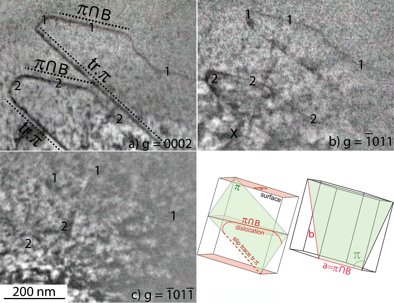
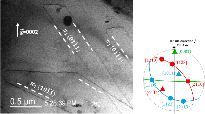
Gliding \hkl¡c+a¿ dislocations in recrystallized Zircaloy-4 are shown in Figures 1 and 2. In Figure 1, it has been possible to determine exactly the Burgers vector using different tilts: the dislocations are visible with diffraction vectors and , but invisible with , thus showing unambiguously that . The dislocation glide plane could be determined from the direction of the slip traces on the surface and from the variations of the projected size of the curved dislocation and of its slip traces with the tilt angle: these dislocations glide in a \hkl(0-11-1) first-order pyramidal planes (Fig. 1). All the slip traces analyzed during our in situ tensile tests lead to a first-order pyramidal plane. When several \hkl¡c+a¿ slip systems were activated in the same grain (Fig. 2), they all correspond to the first-order pyramidal slip plane. In all grains where \hkl¡c+a¿ slip was activated, the corresponding Schmid factors were higher than or equal to 0.36, while the Schmid factors of \hkl¡a¿ prismatic slip systems was smaller than 0.01. As a consequence, no \hkl¡a¿ dislocations was observed at this stage in grains where \hkl¡c+a¿ slip is activated, but \hkl¡a¿ dislocations could be observed in the surrounding grains. As plastic strain increases, some \hkl¡a¿ dislocations could sometimes also be observed in the same grains as \hkl¡c+a¿ dislocations, probably because of the complex mechanical load coming from the deforming surrounding grains, from the appearance of some cracks and from twinning, and also because of crystal rotation. But these \hkl¡a¿ dislocations clearly appear latter than \hkl¡c+a¿ dislocations. We could see some \hkl¡c+a¿ dislocation nucleated on grain boundaries or on twins. But most of the time, \hkl¡c+a¿ dislocations are coming from thick areas of the thin foil which could not be imaged.
In all these in situ straining experiments (Figs. 1 and 2), it can be noticed that the dislocation lines exhibit straight segments perpendicular to the diffraction vector. The \hkl¡c+a¿ preferentially align in a direction defined by the intersection of their first-order pyramidal glide plane with the basal plane, that is, along an \hkl¡a¿ direction. This dislocation orientation is nearly edge with a character defined by . For Zr (), this leads to .
3.2 Dislocation mobility
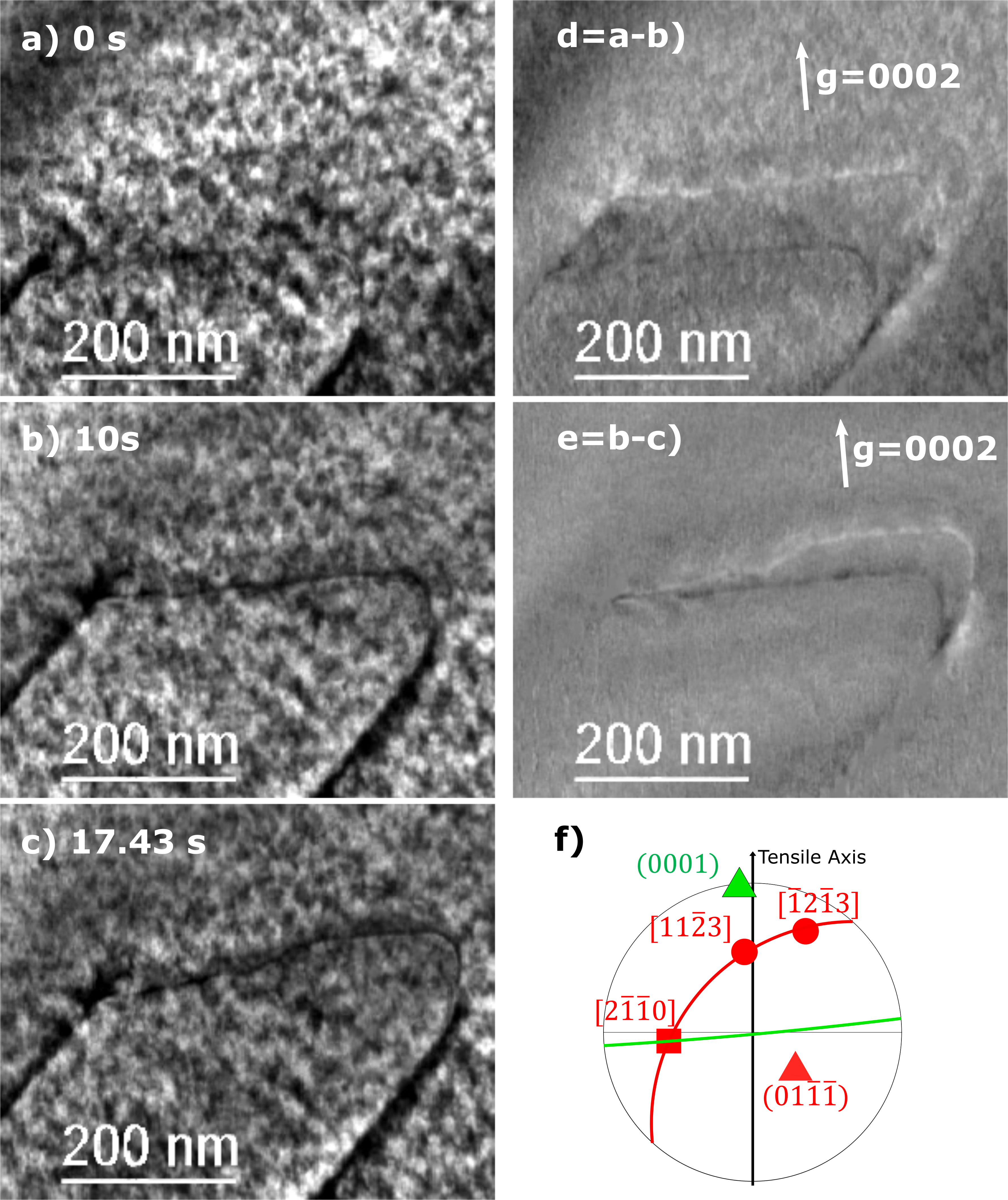
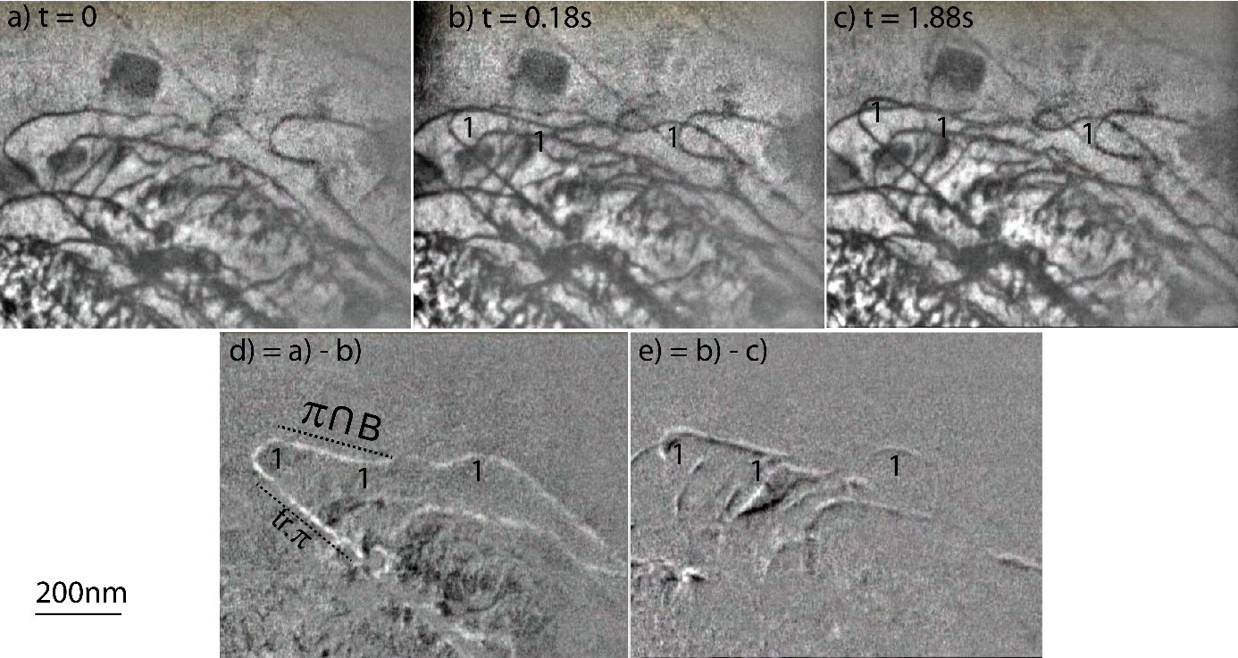
In situ observations of the dislocation motion in recrystallized Zircaloy-4 show that the \hkl¡c+a¿ dislocations aligned along the \hkl¡a¿ direction glide slowly in a rigid manner with occasionally the formation of macro-kinks. This can be seen on Fig. 3, where the \hkl¡c+a¿ dislocation aligned in the \hkl¡a¿ direction is nearly horizontal and the slip traces are the diagonal lines. Dislocation glide is better analysed on Figs. 3d and 3e which are obtained as subtraction of the same area observed at two different times so as to reveal the differences between the two images, and thus the dislocation motion in the time interval. Between the initial time and s, the nearly edge part of the \hkl¡c+a¿ dislocation has kept its straight \hkl¡a¿ orientation while gliding viscously a distance nm. At this time, this dislocation gets pinned in its middle with only one half keeping gliding in the following 7.4 s. This leads to the formation of a macro-kink. After the last frame shown in Fig. 3, the dislocation suddenly escapes from the observation zone, with a much faster motion. Such a fast motion of the nearly edge part of the \hkl¡c+a¿ dislocation has been captured in another in situ straining experiment. In Fig. 6, one can see that the dislocation labeled 1 has arrived suddenly in the observation zone in a time interval s with a long part of the line aligned in the \hkl¡a¿ direction noted on Fig. 6d. In the following 1.7 s, the dislocation moves much more slowly (Fig. 6e). Two mechanisms, leading either to a slow viscous glide or to a fast sudden motion, seem to control the mobility of this nearly edge part of the \hkl¡c+a¿ dislocation.
Other orientations of the \hkl¡c+a¿ dislocation, including the screw part, glide more rapidly with larger jumps than the viscous motion of the \hkl¡a¿ orientation, as can be seen for instance on Fig. 4. The shape of these dislocations segments with other orientations is much more rounded and appears to be driven by minimization of the line tension. Nevertheless, a lot of pinning points can be seen (Figs 1, 4 and 6), showing that these segments are anchored on numerous localized point obstacles.
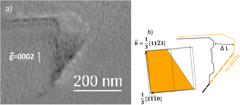
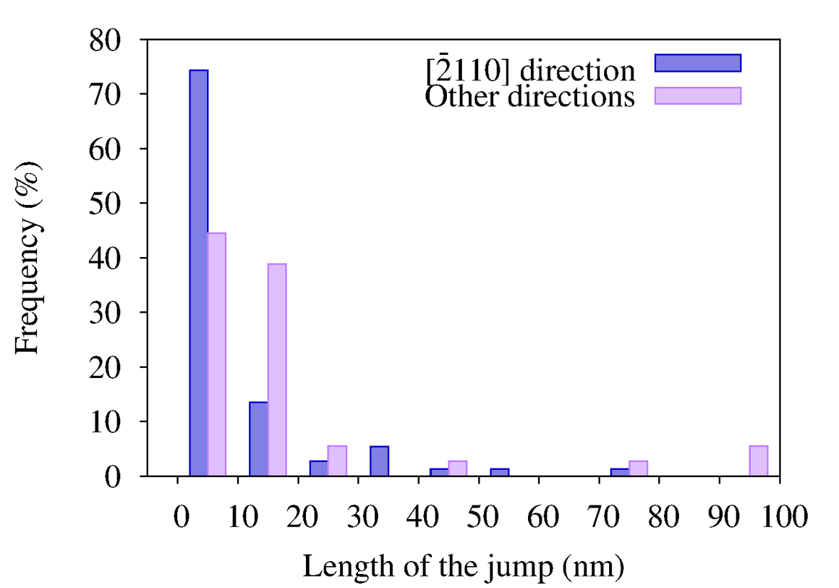
We have tried to evaluate the difference of mobility in the viscous glide regime between the part of the \hkl¡c+a¿ dislocation aligned along the \hkl¡a¿ direction (nearly edge) and the other mixed-screw orientations for the sequence shown in Fig. 3. The glide distance between two frames ( s) is measured for each part of the dislocation (Fig. 4b). If the dislocation does not move in this time interval, this is added to the waiting time of the dislocation. The overall waiting time accounts for 70 of the sequence duration ( s). Only the time intervals corresponding to a dislocation motion are then analyzed, grouping measured glide distances by bins of width 10 nm so as to build a histogram showing jump frequency as a function of glide distances both for the nearly edge and the other mixed orientations of the \hkl¡c+a¿ dislocation (Fig. 5). It then clearly appears that there is a higher frequency of short jumps, smaller than 10 nm, for dislocation lines along the \hkl¡a¿ direction than for the other mixed-screw parts, thus leading to a lower glide velocity of this near edge orientation. The large jump of 100 nm long of the mixed-screw part shown in Fig. 4 corresponds to the tail of the histogram.
3.3 Cross-slip
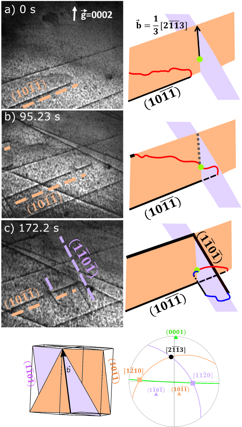
During in situ straining experiments, cross-slip of \hkl¡c+a¿ dislocations has been observed. One of these cross-slip events is illustrated on Fig. 7, where the dislocation exhibits a light contrast and the slip traces a strong contrast. New slip traces appear with another orientation, coming from the initial slip traces. Both slip planes correspond to first-order pyramidal planes. When analyzing carefully the sequence to understand the geometry of the cross-slip event, it is found out that there must be an obstacle along the track of the dislocation. This obstacle could be a nano-hydride, a small precipitate or even a forest dislocation. Because initially the dislocation is along the \hkl¡a¿ direction, it is nearly edge and it cannot cross-slip. When the gliding dislocation meets the obstacle, which seems to be between the middle and the bottom of the thin foil, it is pinned. The part on the left continues to glide and bends towards the screw direction. When aligned along the screw direction, the dislocation cross-slips in the other first-order pyramidal plane.
Four additional slip traces emerge between (Fig. 7a) and s (Fig. 7b). These traces correspond to two \hkl¡c+a¿ dislocations which have also slipped in two other first-order pyramidal planes, leading to two slip traces on the top surface of the thin foil and two on the bottom surface. The slip traces on the top and bottom surfaces are not parallel because of the wedge shape of the thin foil. We have checked that these additional \hkl¡c+a¿ dislocations did not interact with the ones which have cross-slipped.
The process detailed here points out that \hkl¡c+a¿ dislocations can cross-slip when they meet an obstacle and that the cross-slipped plane is also a first-order pyramidal plane.
3.4 Relaxation
When decreasing the stress applied on the specimen, by reducing the displacement of the cross-head from 120 to 100 m, a dislocation has been found to move back on its track (Fig. 8). This dislocation relaxation has only been observed once in Zircaloy-4, but has also been observed in pure Zr. In the case of Zircaloy-4 shown on Fig. 8, it happens for a \hkl¡c+a¿ dislocation which is far from the specific \hkl¡a¿ orientation. When decreasing the applied stress, the dislocation moves back to align in a direction closer to the screw orientation, since screw dislocations have a lower line energy than dislocations with an edge character. This relaxation of the \hkl¡c+a¿ is therefore probably driven by the line tension, thus further showing that the lattice friction is not as strong for these orientations than for the \hkl¡a¿ direction. One also notices that the back motion of this \hkl¡c+a¿ dislocation erases the slip traces on the thin foil, proving that, at least in this particular case, dislocation glide is well confined in a single crystallographic plane.
4 Results in pure Zr
The same in situ TEM straining experiments have been performed at room temperature on pure zirconium. Comparing these observations with the previous ones in Zircaloy-4 gives some insights on alloying effects on the mobility of \hkl¡c+a¿ dislocations.
4.1 Dislocation motion
Like in Zircaloy-4, the slip planes of \hkl¡c+a¿ dislocations have always been found in pure zirconium to correspond to the first-order pyramidal planes (Fig. 9). The dislocations also show some long rectilinear segments in the \hkl¡a¿ direction defined by the intersection of the pyramidal glide plane with the basal plane. Apart from this \hkl¡a¿ orientation, the dislocations are curved, with a shape driven by the line tension. One notices that in pure zirconium the straight portions are longer and better defined than in Zircaloy-4. This shape difference between both zirconium samples is a signature that the difference of lattice friction between this \hkl¡a¿ direction and the other orientations of the \hkl¡c+a¿ dislocations is stronger in pure zirconium than in Zircaloy-4. The presence of numerous solute elements in Zircaloy-4 slow-downs all \hkl¡c+a¿ segments, thus reducing the mobility anisotropy of \hkl¡c+a¿ dislocation. As pure zirconium contains very few impurities, this mobility anisotropy appears more important, with an enhanced relative lattice friction acting against the glide of the straight \hkl¡a¿ orientation.
Like in Zircaloy-4, glide of the straight \hkl¡a¿ orientation of \hkl¡c+a¿ dislocations leads to the creation of macro-kinks (Fig. 9) in pure zirconium. These macro-kinks can either glide along the dislocation line (Fig. 10d) or remain fixed while the dislocation moves slowly (Fig. 10e). Besides this viscous glide of the \hkl¡a¿ orientation, one also observes some large jumps, with therefore the same combination of slow and rapid motion as seen in Zircaloy-4.
A few cross-slip events have been also observed in pure zirconium. They appear, at first glance, less numerous than in Zircaloy-4, but a detailed statistical analysis would be needed to be able to really compare the occurrence of cross-slip in both materials.
4.2 Friction stress
Some relaxation observations have been also performed in pure zirconium. These experiments have been used to estimate the friction stress acting against the glide of the \hkl¡a¿ orientation and of the other orientations, thus characterizing the mobility anisotropy. The friction stress originates from the dislocation core structure, like a possible non planar dissociation, and also from the dislocation interaction with the solute atoms present in the zirconium matrix.
When the applied stress is removed, one observed that the curved parts of the dislocations are gliding back and that their curvature radius increases (Fig. 11). This variation of the curvature radius can be used to estimate the applied stress and the friction stress acting against the glide motion of these curved segments. Using the program Disdi based on line tension calculations in anisotropic elasticity [37], one can deduce from the dislocation curvature the line tension stress . The shape of the loops 1 to 9 under an applied stress shown on Fig. 11a corresponds to a line tension stress between 100 and 150 MPa. When the stress is relieved ( on Fig. 11b), we obtain a line tension stress between 25 and 50 MPa. The applied stress is always in equilibrium with the line tension and the friction stresses, . We therefore deduce a friction stress MPa acting again the glide of curved dislocation and an applied stress MPa. This applied stress corresponds to the friction stress acting against the motion of the straight \hkl¡a¿ parts of the dislocation, because the line tension is zero for a straight dislocation, thus confirming that this friction stress is much higher for this particular orientation.
5 Discussion
5.1 Glide planes and cross-slip
Only glide in first-order pyramidal planes has been observed in our experiments, both in pure zirconium and in Zircaloy-4. This agrees with previous TEM observations [7, 8, 10, 11, 13, 14, 15, 16] which invariably report the same glide plane for \hkl¡c+a¿ dislocations. Only Long et al. [16] have shown that cross-slip in second order pyramidal plane is also possible, with nevertheless first-order pyramidal plane being the main glide plane. As the zirconium alloy studied by Long et al. contains 2.5 wt.% Nb, it is possible that niobium addition promotes the activation of this secondary slip system for \hkl¡c+a¿ dislocations.
Cross-slip events between the two first-order pyramidal planes shared by a single \hkl¡c+a¿ direction have been observed in Zircaloy-4 and in pure zirconium in our experiments, and also in Zr-2.5Nb alloy by Long et al. [14, 15, 16]. Cross-slip activation at room temperature may look surprising as the dislocation microstructure shows dislocations mostly aligned in a direction far from the screw orientation, which should prevent cross-slip. Nevertheless, cross-slip has been observed in our experiments only when the dislocation meets an obstacle, this obstacle forcing the dislocation to adopt locally a screw orientation which can then cross-slip. As \hkl¡c+a¿ dislocations gliding in first-order pyramidal planes are thought to be dissociated in two partials separated by a stable stacking fault [38], the obstacle should also help the dislocation constriction necessary for its propagation then in the cross-slipped plane, in the same way as the Friedel-Escaig mechanism operating in face-centered cubic metals [39, 40]. As less obstacles are present in pure zirconium than in Zircaloy-4, one should expect cross-slip being less active in pure zirconium. This looks in agreement with our observations, although, as mentioned earlier, a detailed statistical analysis would be needed to truly compare cross-slip activity in the two materials.
5.2 Straightening along \hkl¡a¿ direction
One key feature of the glide motion of \hkl¡c+a¿ dislocations is the strong lattice friction existing for the orientation corresponding to the intersection of the pyramidal glide plane with the basal plane, leading to long straight dislocations aligned along this \hkl¡a¿ direction. This important friction exists both in pure zirconium and in Zircaloy-4, thus showing that it certainly derives from an intrinsic core property of this specific orientation. As mentioned in the introduction, this behavior is not specific to zirconium, but can be found in other hcp metals. In Mg, it has been observed that \hkl¡c+a¿ dislocations gliding in second-order pyramidal planes may lock themselves by a non-conservative dissociation in the basal plane when their line direction belongs to this plane [18], a mechanism which has been well described by elasticity [41] and atomistic simulations [21]. For \hkl¡c+a¿ dislocations gliding in first-order pyramidal plane, atomic simulations [42, 43, 44] predict that the same locking mechanism operates, with a non conservative dissociation in the basal plane of the \hkl¡c+a¿ in two partial dislocations separated by a basal stacking fault: . Elastic calculations of the energy variation induced by this dissociation predict that it is also favorable in Zr [45], thus potentially explaining the locking of the \hkl¡c+a¿ when they meet the basal plane.
However our in situ experiments provide some clues that the lattice friction of this \hkl¡a¿ orientation may have a different origin in zirconium. Locking of edge \hkl¡c+a¿ dislocations in Mg by a non conservative dissociation in the basal plane has been correlated with the emission of basal prismatic loops with a stacking fault [18, 46]. No such basal loops were detected in our in situ TEM straining experiments, neither in pure zirconium nor in Zircaloy-4. As the emission of these loops is intimately related to the non conservative dissociation of \hkl¡c+a¿ dislocations in the basal planes, this may be an indication that such a non conservative dissociation does not operate in zirconium at room temperature. Besides, contrary to magnesium [18], \hkl¡c+a¿ dislocations intersecting the basal plane are not completely sessile in zirconium but only suffer a reduced mobility compared to other orientations. Finally, if \hkl¡c+a¿ dislocations lock themselves in the \hkl¡a¿ direction by a non conservative dissociation, i.e. by climb of partial dislocations in the basal plane, one would expect that the locking efficiency would depend on the arrest time. This would lead to dynamic strain ageing and to plastic instabilities which we did not observe in our in situ experiments. The large lattice friction of this \hkl¡a¿ orientation of the \hkl¡c+a¿ dislocation should therefore result from a different mechanism in zirconium.
This non conservative dissociation is not the solely possible mechanism leading to a lattice friction. It has been also observed in Mg that \hkl¡c+a¿ dislocation may emit an \hkl¡a¿ dislocation gliding in the basal plane to leave behind a sessile \hkl¡c¿ dislocation [18]. Nevertheless, this will lead once again to the permanent locking of the \hkl¡c+a¿ dislocation and not only to a reduced mobility. Besides, the extinction tests performed during our in situ experiments (Fig. 1) clearly indicate that the dislocations aligned along the \hkl¡a¿ direction have a \hkl¡c+a¿ and not a \hkl¡c¿ Burgers vector. The possible dissociation appears therefore not compatible with our observations, unless the \hkl¡c¿ and \hkl¡a¿ are so tightly bound that they could not separate and should be considered as a single dislocation [44].
Without going to the emission of a perfect basal \hkl¡a¿ dislocation, Numakura et al.[42, 43] have shown that \hkl¡c+a¿ dislocations intersecting the basal plane can emit a single Shockley partial trailing a basal stacking fault. The corresponding dissociation, , does not require climb of the partial dislocations and leads to a non planar core with a stacking fault in the basal and in the pyramidal planes. Atomistic simulations relying on a generic interatomic potential for hcp metals [42, 43] show that this core is more stable than the planar core dissociated in the pyramidal plane, but that it recombines in this planar core under an applied stress to easily glide then in the pyramidal plane. This non planar core could therefore explain the lattice friction of the \hkl¡a¿ orientation. Its ability to transform in a planar glissile core is also compatible with the jerky glide motion sometimes seen for this \hkl¡a¿ orientation.
5.3 Macro-kinks
One characteristic of the gliding \hkl¡c+a¿ dislocations when they are aligned in the \hkl¡a¿ direction is the presence of macro-kinks on these otherwise straight segments. Recent in situ TEM compression experiments performed in Mg [23] have evidenced the same macro-kinks on the straight portions of \hkl¡c+a¿ dislocations, leading to “stair-like” shapes. Although \hkl¡c+a¿ dislocations are not gliding on the same pyramidal plane in Zr and Mg, their glide motion induces the formation of macro-kinks in both metals. We can reasonably exclude that these macro-kinks are a by-product of a reaction with \hkl¡a¿ dislocations as extinction tests in TEM observations showed that they have the same \hkl¡c+a¿ Burgers vector as the whole dislocation lines. They could arise from a local change of configurations of the \hkl¡c+a¿ dislocation, between an almost sessile core corresponding to the straight segments and a glissile core for the macro-kinks. These macro-kinks are less numerous in pure zirconium than in Zircaloy-4, leading to longer straight dislocations in the former case. Their interaction with the different solute atoms present in solid solution hinder their motion, thus leading to a stronger pinning of these macro-kinks in Zircaloy-4 than in pure zirconium.
5.4 Lattice friction
Our line tension measurements indicate a friction stress of MPa acting against glide of the straight part of \hkl¡c+a¿ dislocations in pure zirconium. This friction has both an intrinsic origin probably due to a complex core of the \hkl¡c+a¿ dislocation for the \hkl¡a¿ orientation as discussed before and an extrinsic one arising from interaction with solute atoms. This friction stress of the less mobile segments should correspond to the yield stress of \hkl¡c+a¿ pyramidal slip at room temperature. Modeling with crystal plasticity their micro-cantilevers bending experiments, Gong et al. [17] obtained for the same slip system a much higher value, MPa, in a commercial pure zirconium. With a higher level of solute elements in commercial pure zirconium than in the pure zirconium used in our experiments, in particular oxygen concentration which is four times higher, this yield stress difference indicates a strong influence of alloying elements. This is further supported by the strongest pinning of gliding dislocations observed in Zircaloy-4 than in pure zirconium.
This reduced mobility of \hkl¡c+a¿ dislocations in alloyed zirconium may appear at first glance in contradiction with the study of Jensen and Backofen [6] who observed that plastic strain along the axis was mostly accommodated by twinning below 300 ∘C in pure zirconium whereas only slip was activated in Zircaloy-4 with very few compressive twins. Although solute elements further hinder glide of dislocations, this hardening contribution appears less important than the impact of the same solute elements on twinning with the suppression of twinning by impurities in zirconium [47], in particular oxygen which addition strongly decreases twin activity [36].
6 Conclusions
In situ TEM straining experiments performed both in pure zirconium and in Zircaloy-4 have shown that \hkl¡c+a¿ dislocations glide exclusively in first-order pyramidal planes at room temperatures, with some cross-slip events between two pyramidal planes sharing the same \hkl¡c+a¿ direction. A characteristic feature of the microstructure is that \hkl¡c+a¿ dislocations align in the \hkl¡a¿ direction defined by the intersection of their glide plane with the basal plane, leading to long straight dislocations. Dislocations segments aligned along this orientation experience a higher lattice friction than others, with a friction stress estimated to MPa for the \hkl¡a¿ orientation instead of MPa for others in pure zirconium. This \hkl¡a¿ orientation exhibits two different glide motions, either viscous or jerky, and its frequent pinning in localized points leads to the creation of macro-kinks. The same dynamic behavior of \hkl¡c+a¿ dislocations has been observed in pure zirconium and in Zircaloy-4, except for a highest friction acting against the motion of all characters in Zircaloy-4 because of the numerous alloying elements in solid solution. The mechanisms controlling the mobility of \hkl¡c+a¿ dislocations in zirconium show strong similarities with the ones operating in other hcp metals, in particular magnesium despite a different glide plane.
Acknowledgments - The authors thank Framatome for providing the raw Zr sponge and the Zircaloy-4 TREX tube, D. Nunes and S. Urvoy (SRMA/CEA) for the preparation of the pure Zr samples and B. Arnal (SRMA/CEA) for thin foils preparation. This work is funded by the French Tripartite Institute (CEA-EDF-Framatome) through the GAINE project.
Appendix A Post-mortem observations
Besides the in situ TEM experiments described in the main text, some post mortem observations have been carried out. The purpose was to check that the dislocation behavior observed in situ in thin foils is typical of bulk plasticity. To this aim, conventional tensile tests on dog-bone Zircaloy-4 specimens taken out of the TREX tube with the tensile axis along the transverse direction have been performed at 350 ∘C up to a deformation of 4. Strained samples have been then observed with a JEOL 2100 TEM operating at 200 kV.
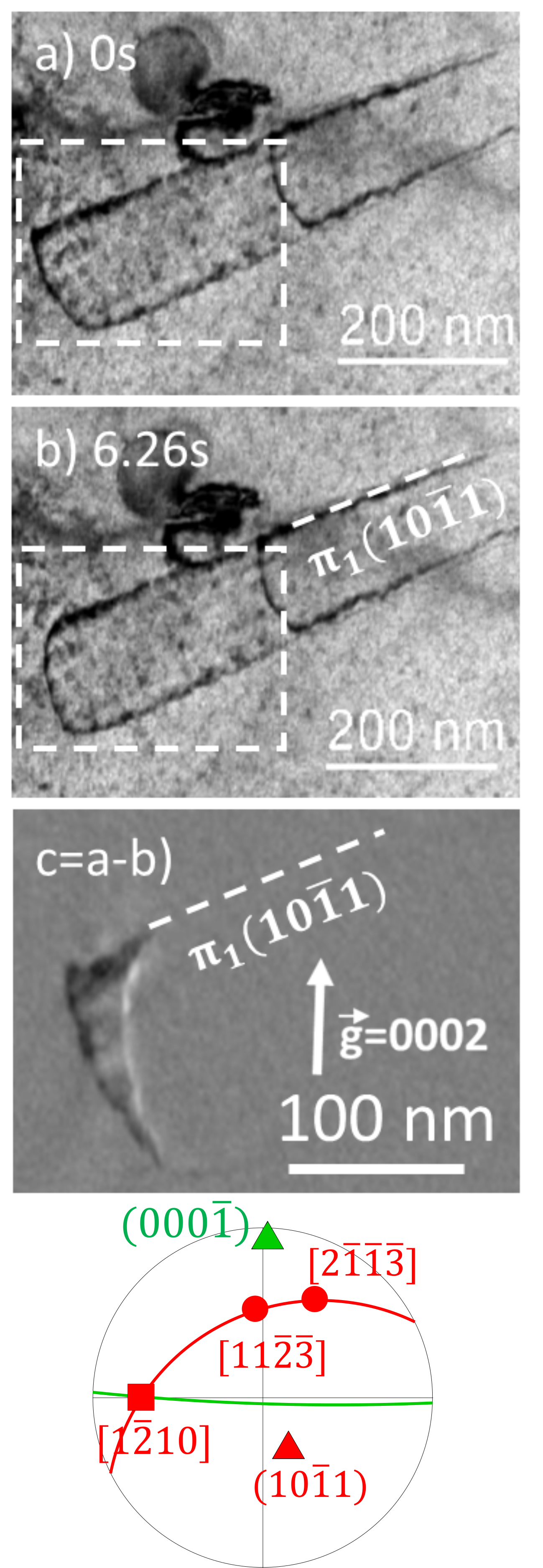
TEM observation with a diffraction vector allows the extinction of all \hkl¡a¿ dislocations to image only dislocations with a \hkl¡c¿ component. Such a post mortem observation is shown in Fig. 12. Using other diffraction vectors, in particular for which the dislocation becomes invisible (Fig. 12c), we could evidence that this dislocation is not pure \hkl¡c¿, but is a \hkl¡c+a¿ dislocation with Burgers vector. Stereoscopic analysis of this dislocation further showed that it is lying in the \hkl(10-1-1) first-order pyramidal plane. This \hkl¡c+a¿ is mainly aligned along an \hkl¡a¿ direction corresponding to the intersection of its pyramidal glide plane with the basal plane. All our post mortem observations, like Fig. 12, reveal the same properties for \hkl¡c+a¿ dislocations, in full agreement with the behavior observed during in situ experiments.
Appendix B Twinning
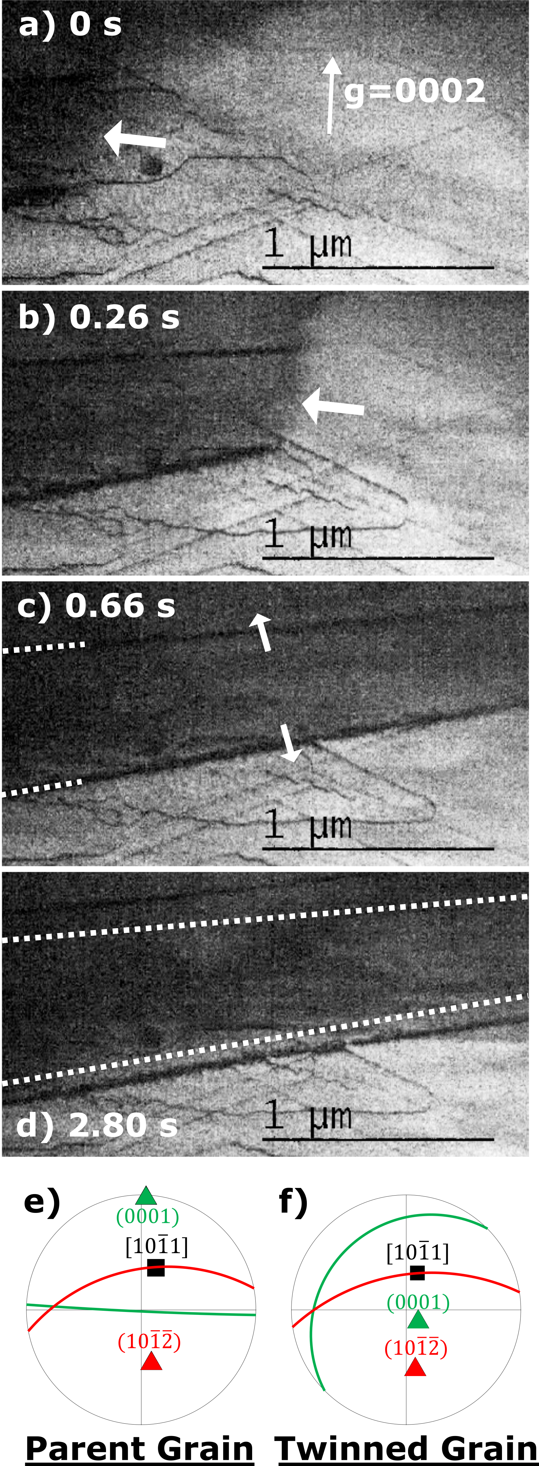
Twining was observed in situ in Zircaloy-4. In one case, the propagation of the twin and its thickening were slow enough to be analyzed (Fig. 13). The forefront of the twin appears to be very diffuse, without any distinct contrast, whereas the edge of the twin exhibits a strong contrast. The velocity of the propagation of the twin forefront was evaluated measuring the distance between each frame, taken every 0.1 s. Because of the rapid velocity of the twin forefront, there are only 6 frames to measure the instantaneous velocity which were equal to 1.24, 1.60, 2.86, 4.27 and 6.03 m/s. Then, after the rapid propagation of the forefront of the twin, the twin is observed to thicken. The thickening velocity in the direction perpendicular to the twin interface is found to be equal to 33.3 nm/s. The twin orientation with respect to the parent grain was analyzed: this is a tension twin, corresponding to the twinning system \hkl[10-11]\hkl(10-1-2).
References
References
- [1] A. T. Motta, D. R. Olander, Light water reactor materials, American Nuclear Society, La Grange Park, Illinois, 2017.
- [2] D. Caillard, J. L. Martin, Thermally activated mechanisms in crystal plasticity, Pergamon, Amsterdam, 2003.
- [3] E. Clouet, D. Caillard, N. Chaari, F. Onimus, D. Rodney, Dislocation locking versus easy glide in titanium and zirconium, Nat. Mater. 14 (2015) 931–936. doi:10.1038/nmat4340.
- [4] D. Caillard, M. Gaumé, F. Onimus, Glide and cross-slip of a -dislocations in Zr and Ti, Acta Mater. 155 (2018) 23–34. doi:10.1016/j.actamat.2018.05.038.
- [5] E. Tenckhoff, Operation of dislocations with type Burgers vector during deformation of zirconium single-crystals, Z. Metallkde. 63 (1972) 192.
- [6] J. A. Jensen, W. A. Backofen, Deformation and fracture of alpha zirconium alloys, Can. Metall. Q. 11 (1972) 39–51. doi:10.1179/cmq.1972.11.1.39.
- [7] A. Akhtar, Compression of zirconium single crystals parallel to the c-axis, J. Nucl. Mater. 47 (1973) 79–86. doi:10.1016/0022-3115(73)90189-X.
- [8] O. T. Woo, G. J. C. Carpenter, S. R. MacEwen, -component dislocations in zirconium alloys, J. Nucl. Mater. 87 (1979) 70–80. doi:10.1016/0022-3115(79)90126-0.
- [9] R. A. Holt, M. Griffiths, R. W. Gilbert, c-component dislocations in Zr-2.5 wt% Nb alloy, J. Nucl. Mater. 149 (1987) 51–56. doi:10.1016/0022-3115(87)90497-1.
- [10] P. Merle, Evidence of pyramidal slip mode in cold-rolled zircaloy-4 sheets, J. Nucl. Mater. 144 (1987) 275–277. doi:10.1016/0022-3115(87)90040-7.
- [11] H. Numakura, Y. Minonishi, M. Koiwa, slip in zirconium, Philos. Mag. A 63 (1991) 1077–1084. doi:10.1080/01418619108213938.
- [12] R. J. McCabe, E. K. Cerreta, A. Misra, G. C. Kaschner, C. N. Tomé, Effects of texture, temperature and strain on the deformation modes of zirconium, Philos. Mag. 86 (2006) 3595–3611. doi:10.1080/14786430600684500.
- [13] F. Long, M. R. Daymond, Z. Yao, Deformation mechanism study of a hot rolled Zr-2.5Nb alloy by transmission electron microscopy. I. Dislocation microstructures in as-received state and at different plastic strains, J. Appl. Phys. 117 (2015) 094307. doi:10.1063/1.4913605.
- [14] F. Long, M. R. Daymond, Z. Yao, M. A. Kirk, Deformation mechanism study of a hot rolled Zr-2.5Nb alloy by transmission electron microscopy. II. In situ transmission electron microscopy study of deformation mechanism change of a Zr-2.5Nb alloy upon heavy ion irradiation, J. Appl. Phys. 117 (2015) 104302. doi:10.1063/1.4913614.
- [15] F. Long, L. Balogh, M. R. Daymond, Evolution of dislocation density in a hot rolled Zr–2.5Nb alloy with plastic deformation studied by neutron diffraction and transmission electron microscopy, Philos. Mag. 97 (2017) 2888–2914. doi:10.1080/14786435.2017.1356940.
- [16] F. Long, J. Kacher, Z. Yao, M. R. Daymond, A tomographic TEM study of tension-compression asymmetry response of pyramidal dislocations in a deformed Zr-2.5Nb alloy, Scr. Mater. 153 (2018) 94–98. doi:10.1016/j.scriptamat.2018.04.043.
- [17] J. Gong, T. B. Britton, M. A. Cuddihy, F. P. Dunne, A. J. Wilkinson, prismatic, basal, and slip strengths of commercially pure Zr by micro-cantilever tests, Acta Mater. 96 (2015) 249–257. doi:10.1016/j.actamat.2015.06.020.
- [18] J. F. Stohr, J. P. Poirier, Étude en microscopie électronique du glissement pyramidal dans le magnésium, Philos. Mag. 25 (1972) 1313–1329. doi:10.1080/14786437208223856.
- [19] J. Geng, M. Chisholm, R. Mishra, K. Kumar, The structure of type dislocation loops in magnesium, Philos. Mag. Lett. 94 (2014) 1–10. doi:10.1080/09500839.2014.916423.
- [20] J. Geng, M. Chisholm, R. Mishra, K. Kumar, An electron microscopy study of dislocation structures in Mg single crystals compressed along [0001] at room temperature, Philos. Mag. 95 (2015) 3910–3932. doi:10.1080/14786435.2015.1108531.
- [21] Z. Wu, W. A. Curtin, The origins of high hardening and low ductility in magnesium, Nature 526 (2015) 62–67. doi:10.1038/nature15364.
- [22] Z. Wu, R. Ahmad, B. Yin, S. Sandlöbes, W. A. Curtin, Mechanistic origin and prediction of enhanced ductility in magnesium alloys, Science 359 (2018) 447–452. doi:10.1126/science.aap8716.
- [23] D. Zhang, L. Jiang, X. Wang, I. J. Beyerlein, A. M. Minor, J. M. Schoenung, S. Mahajan, E. J. Lavernia, In situ transmission electron microscopy investigation on slip in Mg, J. Mater. Res. 34 (2019) 1499–1508. doi:10.1557/jmr.2018.487.
- [24] Y. Minonishi, S. Morozumi, H. Yoshinaga, slip in titanium, Scr. Metall. 16 (1982) 427–430. doi:10.1016/0036-9748(82)90166-1.
- [25] H. Numakura, Y. Minonishi, M. Koiwa, slip in titanium polycrystals at room temperature, Scr. Metall. 20 (1986) 1581–1586. doi:10.1016/0036-9748(86)90399-6.
- [26] F. Long, L. Balogh, D. W. Brown, P. Mosbrucker, T. Skippon, C. D. Judge, M. R. Daymond, Effect of neutron irradiation on deformation mechanisms operating during tensile testing of Zr–2.5Nb, Acta Mater. 102 (2016) 352–363. doi:10.1016/j.actamat.2015.09.032.
- [27] D. Caillard, M. Rautenberg, X. Feaugas, Dislocation mechanisms in a zirconium alloy in the high-temperature regime: An in situ TEM investigation, Acta Mater. 87 (2015) 283–292. doi:10.1016/j.actamat.2015.01.016.
- [28] J. Drouet, L. Dupuy, F. Onimus, F. Mompiou, A direct comparison between in-situ transmission electron microscopy observations and dislocation dynamics simulations of interaction between dislocation and irradiation induced loop in a zirconium alloy, Scr. Mater. 119 (2016) 71–75. doi:10.1016/j.scriptamat.2016.03.029.
- [29] M. Gaumé, P. Baldo, F. Mompiou, F. Onimus, In-situ observation of an irradiation creep deformation mechanism in zirconium alloys, Scr. Mater. 154 (2018) 87–91. doi:10.1016/j.scriptamat.2018.05.030.
- [30] D. Chaubet, J. Fondère, B. Bacroix, Strain-anneal growth of zr 701 large crystals, Mater. Sci. Eng. A 300 (2001) 245–253. doi:10.1016/S0921-5093(00)01785-8.
- [31] K. Y. Zhu, D. Chaubet, B. Bacroix, F. Brisset, A study of recovery and primary recrystallization mechanisms in a Zr–2Hf alloy, Acta Mater. 53 (2005) 5131–5140. doi:10.1016/j.actamat.2005.07.034.
- [32] L. Tournadre, F. Onimus, J.-L. Béchade, D. Gilbon, J.-M. Cloué, J.-P. Mardon, X. Feaugas, O. Toader, C. Bachelet, Experimental study of the nucleation and growth of c-component loops under charged particle irradiations of recrystallized zircaloy-4, J. Nucl. Mater. 425 (2012) 76––82. doi:10.1016/j.jnucmat.2011.11.061.
- [33] N. Gharbi, F. Onimus, D. Gilbon, J.-P. Mardon, X. Feaugas, Impact of an applied stress on c-component loops under Zr ion irradiation in recrystallized Zircaloy-4 and M5®, J. Nucl. Mater. 467 (2015) 785–801. doi:10.1016/j.jnucmat.2015.10.009.
- [34] E. J. Rapperport, C. S. Hartley, Deformation modes of zirconium at 77∘, 575∘, and 1075∘K, Trans. AIME 218 (1960) 869–876.
- [35] M. H. Yoo, J. K. Lee, Deformation twinning in h.c.p. metals and alloys, Philos. Mag. A 63 (1991) 987–1000. doi:10.1080/01418619108213931.
- [36] M. Viltange, M. Biget, O. Dimitrov, Influence de l’oxygène sur le maclage, la production et la restauration de défauts spécifiques dans le zirconium deformé à très basse température, J. Nucl. Mater. 127 (1985) 231––238. doi:10.1016/0022-3115(85)90360-5.
- [37] J. Douin, P. Veyssière, P. Beauchamp, Dislocation line stability in Ni3Ai, Philos. Mag. A 54 (1986) 375–393. doi:10.1080/01418618608240722.
- [38] D. Rodney, L. Ventelon, E. Clouet, L. Pizzagalli, F. Willaime, Ab initio modeling of dislocation core properties in metals and semiconductors, Acta Mater. 124 (2017) 633–659. doi:10.1016/j.actamat.2016.09.049.
- [39] J. Friedel, Dislocations, Pergamon Press, Oxford, 1964.
- [40] B. Escaig, Sur le glissement dévié des dislocations dans la structure cubique à faces centrées, J. Phys. Paris 29 (1968) 225–239. doi:10.1051/jphys:01968002902-3022500.
- [41] S. Agnew, L. Capolungo, C. Calhoun, Connections between the basal I1 “growth” fault and dislocations, Acta Mater. 82 (2015) 255–265. doi:10.1016/j.actamat.2014.07.056.
- [42] H. Numakura, Y. Minonishi, M. Koiwa, Atomistic study of dislocations in h.c.p. crystals. i. structure of the dislocation cores, Philos. Mag. A 62 (1990) 525–543. doi:10.1080/01418619008244917.
- [43] H. Numakura, Y. Minonishi, M. Koiwa, Atomistic study of dislocations in h.c.p. crystals. II. motion of the dislocations, Philos. Mag. A 62 (1990) 545–556. doi:10.1080/01418619008244917.
- [44] Z. Wu, W. Curtin, Intrinsic structural transitions of the pyramidal I dislocation in magnesium, Scripta Mater. 116 (2016) 104–107. doi:10.1016/j.scriptamat.2016.01.041.
- [45] Z. Wu, B. Yin, W. A. Curtin, Energetics of dislocation transformations in hcp metals, Acta Mater. 119 (2016) 203–217. doi:10.1016/j.actamat.2016.08.002.
- [46] S. Sandlöbes, M. Friák, S. Zaefferer, A. Dick, S. Yi, D. Letzig, Z. Pei, L.-F. Zhu, J. Neugebauer, D. Raabe, The relation between ductility and stacking fault energies in Mg and Mg–Y alloys, Acta Mater. 60 (2012) 3011–3021. doi:10.1016/j.actamat.2012.02.006.
- [47] A. M. Garde, E. Aigeltinger, R. E. Reed-Hill, Relationship between deformation twinning and the stress-strain behavior of polycrystalline titanium and zirconium at 77 K, Metall. Trans. 4 (1973) 2461–2468. doi:10.1007/bf02669391.