Magnetism and stability of all primitive stacking patterns in bilayer chromium trihalides
Abstract
Chromium trihalides, CrX3 (with X = Cl, Br, I), are a family of layered magnetic materials that can be easily exfoliated to provide ferromagnetic monolayers. When two layers are stacked together to form a bilayer the interlayer exchange coupling can be either ferromagnetic or antiferromagnetic depending on the stacking sequence. Here we combine crystallographic arguments based on the close-packing condition with first-principles simulations to enumerate all possible stacking patterns in CrX3 bilayers that preserve the spatial periodicity of each layer. We recover all configurations observed in bulk crystals and disclose stacking sequences with no bulk counterpart where the two layers have opposite chirality. Stacking sequences are ranked according to their relative stability and a preferential interlayer magnetic ordering is assigned to each of them. Simulations provide a consistent picture to frame all current experimental observations on bulk and exfoliated CrX3 crystals, with interesting implications for future measurements, including synthetic bilayers with non-standard stacking patterns.
I Introduction
Van der Waals magnetic materials have always been a source of fascinating phenomena deJong1990 that are now attracting revived interest owing to the possibility of exfoliating these compounds down to the monolayer limit Burch_review_2018 ; Gong_review_2019 ; Gibertini_review_2019 ; Mak_review_2019 . Among these, the family of chromium trihalides (CrX3, X = Cl, Br, I) has emerged as a promising playground for experimental Huang2017 ; Song2018 ; Klein2018 ; Wang2018 ; Kim2018 ; Ghazaryan2018 ; Cai2019 ; Klein2019 ; Wang2019 ; Kim2019 ; Kim2019b ; Kim2019hall and theoretical Sivadas2018 ; Soriano2019 ; Jiang2019theory ; Jang2019 ; Lei2019 ; Cardoso2018 ; Tong2018 ; Pizzochero2020 ; Soriano2020 explorations. In particular, the magnetic properties of atomically thin CrI3 Huang2017 ; Song2018 ; Klein2018 ; Wang2018 ; Kim2018 can be easily manipulated by external controls such as electric fields Jiang2018field , doping Huang2018 ; Jiang2018doping , and pressure Song2019pressure ; Li2019 , allowing the realization of spin-sensitive devices Jiang2019 ; Song2019 , although practical applications are limited by the low critical temperature.
Bulk CrX3 crystals are magnetic insulators where spins are ferromagnetically aligned within each layer, while the interlayer exchange coupling depends on the halogen. In CrBr3 and CrI3, all layers share the same spin orientation, giving rise to an overall ferromagnetic (FM) behaviour Tsubokawa1960 ; McGuire2015 , while CrCl3 is a layered antiferromagnet with neighbouring layers having spins pointing in opposite directions (so called “A-type” ordering) Cable1961 ; McGuire2017 . Another difference arises from the lighter atomic number of Cl atoms, which leads to reduced spin-orbit coupling effects, so that spins are oriented parallel to the layers in CrCl3 and perpendicular in CrBr3 and CrI3.
In addition to the magnetic phase transition at low temperature, CrX3 crystals undergo a structural phase transition at higher temperatures from a high-temperature monoclinic phase to a low-temperature rhombohedral phase Morosin1964 ; McGuire2015 ; Djurdjic2018 ; Samuelsen1971 . Across the transition, the structure of each layer remains essentially unaffected, with the main difference between the two phases being the stacking sequence of the layers McGuire2015 . At room temperature, only CrBr3 is already in the low temperature structure, while CrI3 and CrCl3 are still in the monoclinic phase. At temperatures below the magnetic transition, instead, all members of the chromium trihalide family share the same rhombohedral structure (see table 1).
When thinned down to few atomic layers, CrI3 has been reported to display A-type antiferromagnetic (AF) order Huang2017 , giving rise to a strong spin-filtering effect and a large magnetoresistance in tunnelling devices Song2018 ; Klein2018 ; Wang2018 ; Kim2018 . The different magnetic ordering of atomically thin and bulk CrI3 has been long puzzling, especially in view of the apparently similar behaviour of CrBr3 and CrCl3 multilayers with respect to their 3D counterparts Ghazaryan2018 ; Kim2019 ; Kim2019hall ; Klein2019 ; Wang2019 ; Cai2019 . First-principles simulations have provided a possible solution to this conundrum by demonstrating a strong connection between the stacking pattern and the magnetic ground state Wang2018 ; Sivadas2018 ; Soriano2019 ; Jiang2019theory ; Jang2019 ; Lei2019 , predicting that for CrI3 the monoclinic phase should be AF while the rhombohedral phase is FM.
Raman spectroscopy Ubrig2019 and non-linear optical measurements Sun2019 have validated this picture by showing that bulk CrI3 is rhombohedral at low temperature, consistently with the bulk FM ordering, while in atomically-thin samples the stacking sequence is monoclinic, thus explaining the AF interlayer coupling (also present in superficial layers Niu2020 ; Li2020 ). A monoclinic structure has been reported also in thin CrCl3, while keeping the same A-type AF order as in its bulk rhombohedral form, although with an enhanced interlayer coupling Klein2019 . For CrBr3, no experimental result is currently available on the stacking pattern in thin crystals, although clear indications exist that they preserve the bulk FM interlayer coupling Ghazaryan2018 ; Kim2019 ; Kim2019hall .
To close the circle and provide a consistent picture for all current experimental results on atomically thin CrX3 samples, here we combine general crystallographic arguments with first-principles simulations to explore the magnetic ground state and the relative stability of all possible stacking patterns in bilayer chromium trihalides that preserve the spatial periodicity of each layer (i.e. primitive). We extend previous results on CrI3 to CrBr3 and CrCl3 and disclose stacking sequences that have no bulk counterpart but could be relevant in synthetic crystals Chen2019 . The theoretical scenario that arises suggests that atomically thin CrBr3 should display a rhombohedral structure, differently from the other chromium trihalides CrI3 and CrCl3, as a result of the higher critical temperature for the structural phase transition, which makes CrBr3 rhombohedral –and not monoclinic– at the temperatures at which exfoliation takes place.
| CrCl3 | CrBr3 | CrI3 | |
|---|---|---|---|
| bulk | AF36; 37 | FM34 | FM35 |
| rhomb.38 | rhomb.40 | rhomb.35; 39 | |
| multilayers | AF12; 14; 13; 15 | FM11; 17; 15 | AF6; 7; 8; 9; 10 |
| monocl.13 | – | monocl.42; 41 |
II Methods
First-principles simulations are performed within density-functional theory (DFT) using the Quantum ESPRESSO distribution Giannozzi2009 ; Giannozzi2017 . To account for van der Waals interactions between the layers, the spin-polarised extension Thonhauser2015 of the revised vdw-DF2 exchange-correlation functional Hamada2014 ; Lee2010 is adopted, truncating spurious interactions between artificial periodic replicas along the vertical direction Rozzi2006 ; Ismail-Beigi2006 ; Sohier2017 . The Brillouin zone is sampled with a -centered Monkhorst-Pack grid. Pseudopotentials are taken from the Standard Solid-State Pseudopotential (SSSP) accuracy library Prandini2018 ; Garrity2014 ; DalCorso2014 (v1.0) with increased cutoffs of 60 Ry and 480 Ry for wave functions and density, respectively. Total energy calculations as a function of the relative displacement between the layers are performed without atomic relaxations, by taking the structure of DFT-relaxed monolayers with the experimental lattice parameter and interlayer separation. For line scans, atomic positions are relaxed by reducing the force acting on atoms below a threshold of 26 meV/Å, while keeping fixed the in-plane coordinates of Cr atoms. The threshold is reduced to 3 meV/Å without constraints to evaluate the relative stability of the different stacking configurations, while also optimising the lattice parameter and cell angle (for non-hexagonal systems) using an equation-of-state approach. Calculations are managed and automated using the AiiDA materials informatics infrastructure Pizzi2016 ; Huber2020 .
III Results and discussion
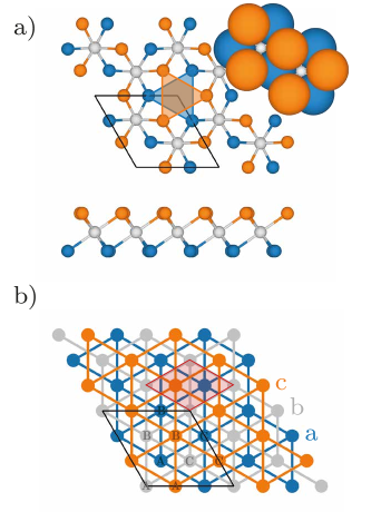
The crystal structure of monolayer CrX3 is reported in Fig. 1a), and consists of three atomic planes: a layer of chromium atoms (grey) sandwiched between halogen layers, reported with different colours (orange and blue) to distinguish the top and bottom plane. The structure can be rationalised by noting that each halogen layer forms a planar triangular sublattice (although slightly distorted) and that the two planes are close-packed (see the top right corner of Fig. 1a). Chromium atoms occupy octahedral interstitials, which themselves form a third triangular lattice, although only 2/3 of the sites are occupied. The three close-packed triangular sublattices are shown in Fig. 1b) with different colours (blue, grey, and orange) and named a, b, and c. Because 1/3 of the octahedral interstitials are empty, the unit cell of CrX3 (black solid line) is larger than the unit cell of a single triangular sublattice (red shade), and represents a supercell rotated by 30∘.
Once the halogen triangular sublattices are specified, the Cr sublattice is enforced by the close-packing condition and the only degree of freedom is the choice of the empty site among three possibilities (marked A, B, and C, in Fig. 1). Thus the structure of a monolayer can be identified by specifying the two halogen triangular sublattices and the empty site in the chromium layer. For instance, in Fig. 1a) the bottom halogen plane corresponds to the “a” sublattice, while the top halogen plane to the “c” sublattice. Cr atoms belong to the “b” sublattice with the “A” site empty. We denote this structure as “aAbc”, where the left (right) small letter denotes the bottom (top) halogen sublattice while the capital letter identifies the empty site in the Cr layer, with a subindex specifying the corresponding sublattice.
We can thus see that CrX3 monolayers can exist in two inequivalent forms. Fixing an arbitrary choice of the origin at the empty site uniquely determines the Cr layer to be Ab. The close-packing condition allows only two possible choices for the halogen planes: aAbc (as in Fig. 1a) and cAba (with top and bottom halogen planes exchanged). The difference between the two can be best visualised by considering the halogen atoms forming the octahedral cage around the empty site. In the aAbc case of Fig. 1a), the top (bottom) halogens make a right (left) pointing triangle, while the opposite is true in the cAba case. We thus have two possibile chiralities for a monolayer, identified by the direction of the triangles in the top plane. The left chirality arises when the labels of the sublattices in the three atomic planes are an even permutation of “abc” (as in Fig. 1a), while the right chirality occurs for odd permutations (e.g. “cba”). The two chiral structures can be obtained one from the other either by exchanging the top and bottom halogen planes, or equivalently by a rotation or a mirror reflection (as it is typical of enantiomers).
| First layer | Chirality | Second Layer | Translation | Short name | Point group |
| aAbc | same | aAbc | (0,0) | AA | m () |
| aBbc | AB | () | |||
| aCbc | AC | ||||
| bAca | HT | () | |||
| bBca | |||||
| bCca | |||||
| opposite | aAcb | rHT | m () | ||
| aBcb | |||||
| aCcb | |||||
| bAac | rHT’ | m () | |||
| bBac | |||||
| bCac |
We now turn our attention to the possible configurations of bilayer CrX3. We restrict to primitive stacking arrangements that preserve the translational invariance of each layer, that is with the same (primitive) unit cell as a monolayer. The most stable configurations of the bilayer are expected to follow the same close-packing conditions of the monolayer. Choosing for definiteness the bottom layer in the aAbc form, the bottom halogen plane of the second layer needs to be in the “a” or “b” sublattice. In each case, we have then two possible choices for the top halogen plane sublattice that are compatible with the close-packing condition, and three possibilities for the empty site of the Cr layer. We thus expect possible stable configurations of the bilayer, listed in table 2. In half of them the two layers share the same chirality, while the chirality is different in the other six cases.
In Fig. 2 we report a schematic picture of the different stacking sequences in table 2, where the orange and blue dashed (solid) lines highlight the triangles corresponding respectively to the top and bottom halogens around the empty site in the first (second) layer. When the chirality is the same, we can interpret the second layer as obtained from the first one by a rigid translation, which has both an in-plane (shown in the figure) and out-of-plane component. When the chirality is different, the second layer can still be obtained from the fist one by a rigid translation, but we need to perform first a rotation by (or a vertical mirror reflection).
In the bulk form, all layers have the same chirality, so we should expect to find the bulk stacking sequences among these cases. Indeed, two consecutive layers in the rhombohedral phase share the same sublattices in the halogen planes, while the position of the empty site is different. In table 2, this situation corresponds to the second layer being either aBbc or aCbc (with the first one being aAbc). Since the information on the halogens is redundant in the two layers, these configurations are typically denoted simply as AB or AC from the position of the empty site, and they are equivalent up to a redefinition of the lattice vectors (and thus have the same point group). In principle, also another possibility arises when the two layers share the same halogen sublattices, that is when also the empty position is the same, thus corresponding to an AA stacking sequence. The high-temperature (HT) monoclinic stacking arrangement can also be recovered. It corresponds to the second layer being bAca, bBca, or bCca, corresponding to a rigid translation along one of three equivalent high-symmetry directions. Translations along the same lines but in opposite directions would give rise to a HT’ configuration (with the second layer being either cAab, cBab, or cCab). This HT’ configuration is indistinguishable from the standard HT bulk arrangement when only Cr atoms are considered. Nonetheless, it does not satisfy the close-packing condition as the halogen planes facing the van der Waals gap share the same “c” sublattice and thus sit on top of each other, so that this configuration is expected to be unstable.
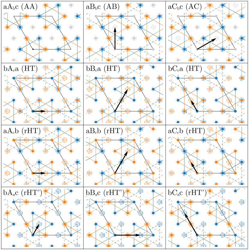
Stacking sequences where the two layers have different chirality do not have a bulk counterpart, although they can be realised in synthetic bilayers grown by molecular beam epitaxy Chen2019 . Among the six possibilities, listed in table 2, that satisfy the close-packing condition, only two are inequivalent up to a redefinition of the lattice vectors. They correspond to the same relative translation between the layers as the HT and HT’ discussed above, but with the second layer now rotated by , and are thus denoted rHT and rHT’. Differently from the case of pure translations when the HT configuration is stable while the HT’ is not, the rHT and rHT’ stacking sequences both satisfy the close-packing condition. Even more compelling, the two arrangements are energetically indistinguishable as they differ only by the definition of the positive vertical direction. The only symmetry element is a vertical mirror plane that contains the translation vector between the layers, so that such configurations are monoclinic.
To verify that the configurations listed in table 2, predicted from crystallographic arguments based on the close-packing condition, are the only (meta)stable primitive stacking sequences for bilayer CrX3, we perform first-principles DFT simulations as a function of the relative in-plane displacement between the two layers, with either the same or opposite chirality. The vertical separation between the layers is either kept fixed or optimised as specified below. Calculations are carried out assuming both a FM and a AF alignment between the layers, with a corresponding total energy and . For each displacement , it is then possible to evaluate the ground-state energy and the energy difference expressing the preference towards a FM/AF alignment. In particular, we can relate the energy difference to an effective interlayer exchange coupling , i.e. , with leading to an AF state while a FM alignment is expected when .
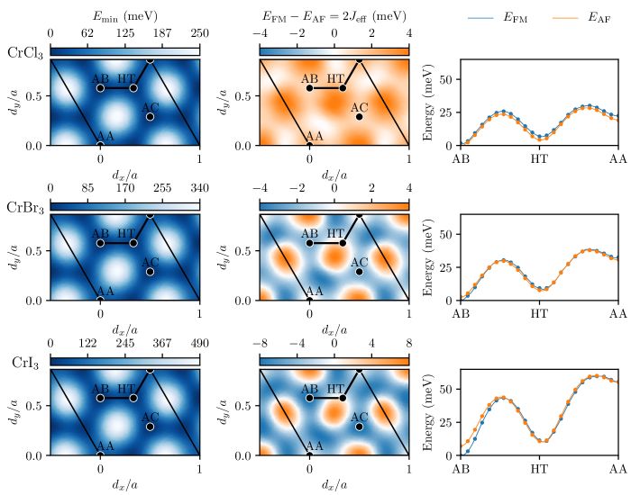
We first consider the case of two layers with the same chirality. The first column of Fig. 3 shows the minimum energy as a function of and while keeping fixed at the bulk (rhombohedral) value for all CrX3 bilayers with X = Cl, Br, and I. In all cases, two equivalent global minima are found at a relative displacement corresponding to the AB and AC configurations, and thus to the rhombohedral stacking sequence. This is consistent with the rhombohedral structure being the most stable phase at low temperature. Additional local minima are present and correspond to the HT and AA configurations. In particular, the monoclinic HT arrangement is very close in energy to the stable AB configuration, consistently with the experimental observation of the monoclinic phase at sufficiently high temperature. As expected, the HT’ configuration is unstable and represents a local maximum for .
In the central panels we show the energy difference between the FM and AF configurations in order to assess the preferential interlayer magnetic order of a given stacking arrangement. As already pointed out Wang2018 ; Sivadas2018 ; Soriano2019 ; Jiang2019theory ; Jang2019 ; Lei2019 , for bilayer CrI3 there is a strong connection between the stacking sequence and the interlayer spin alignment. The AB arrangement is FM, while the AA and HT configurations have a mild preference for an AF order. A similar situation is found for CrBr3, although with a tendency to increase with respect to CrI3, and thus to suppress FM order in favour of the AF state. The suppression is further enhanced for CrCl3, where the AF alignment is preferred irrespective of the relative translation between the layers, although largely depends on and . In all cases, the largest AF interlayer exchange coupling is obtained for a configuration corresponding to , dubbed “special” in Ref. Chen2019, . This is consistent with the AF order measured in Ref. Chen2019 for synthetic CrBr3 bilayers. Nonetheless, it is surprising that this configuration is experimentally accessible since, according to the present simulations, it should not be dynamically stable as it does not represent a local minimum (nor a local maximum) in the energy landscape.
To compare in more detail the energy of the FM and AF alignments, in the right panels we show their dependence on the stacking sequence along a path (passing through the metastable configurations) highlighted with thick black lines in the left and central panels. In this case, the atomic structure is fully relaxed, including the interlayer distance , while keeping fixed the in-plane coordinates of the Cr atoms in order to maintain a given configuration during the force minimisation. All ground-state magnetic orderings discussed above are confirmed, although with a better estimation of the interlayer . These plots also give more insight on energy barriers separating the three metastable configurations. In particular, the very small potential barrier protecting the AA arrangement might be responsible (together with the high energy difference with respect to the AB and HT configurations) for its absence in current experiments under standard conditions, both for bulk and atomically thin samples.
Interestingly we also note that the energy minimum associated with the HT configuration does not necessarily occur for the expected translations in table 2 (e.g. ), and might even be slightly different for the FM and AF state. This is due to the fact that in the HT configuration the symmetry is reduced to monoclinic and the positions of Cr atoms (and thus the relative translation) are not enforced by symmetry, although deviations from the ideal structure are typically small.
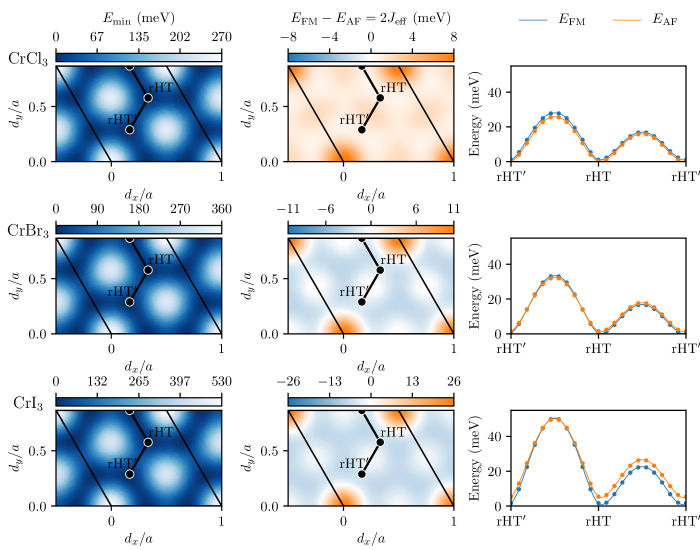
The above situation changes when the two layers have different chirality, i.e. when the second layer is obtained from the first one by performing a rotation (or a vertical mirror reflection) before the relative translation. The corresponding energy landscape is reported in Fig. 4. Although stacking configurations are indistinguishable from the ones in Fig. 3 when only Cr atoms are considered, the energy profile is completely different, signalling the uttermost importance of the halogen arrangement in determining the stability of a stacking sequence. Moreover, also the difference between the FM and AF alignment is largely affected. This means that extending the current results to arbitrary rotation angles and non-primitive unit cells (relevant for twisted bilayers) is far from trivial, as the precise location of the halogens –and not only of the Cr atoms– is crucial in determining the stability and magnetic order of bilayers.
A more detailed analysis shows that the only local minima in correspond to the rHT and rHT’ identified in table 2 using crystallographic arguments. Similarly, the local maxima correspond to the rotated analogues of the AA, AB, and AC arrangements (denoted rAA, rAB, and rAC), which are correctly marked as unstable by the close-packing condition as in this case the halogen layers facing the van-der-Waals gap would sit exactly on top of each other. Allowing for atomic relaxation, including the interlayer distance, provides a more accurate estimation of the energy profile between the local minima at the rHT and rHT’ configurations, as shown in the right panels for configurations along the path highlighted with thick black lines in the other panels. The two rotated monoclinic sequences are energetically equivalent, as expected, but are separated by different barriers. The highest barrier occurs when passing though a saddle point in between the rAB and rAC configurations, while the barrier is lower when the saddle point is between the rAA and the rAB (or rAC) arrangements.
Concerning the magnetic order, bilayer CrCl3 prefers an AF alignment irrespective of the relative translation between the layers also in this case of opposite chirality. CrBr3 and CrI3 behave similarly, with a FM ground state favoured for most configurations, including in particular the locally stable rHT and rHT’, while AF order would be present only close to the unstable rAA stacking sequence. Interestingly, we predict a FM alignment in bilayer CrBr3 for , consistently with the observations in Ref. Chen2019 . Nonetheless, also in this case the experimentally reported stacking sequence, dubbed “bridge I” Chen2019 , is predicted to be dynamically unstable.
| () | |||
|---|---|---|---|
| CrCl3 | CrBr3 | CrI3 | |
| AB | () | () | () |
| HT | () | () | () |
| AA | () | () | () |
| rHT | () | () | () |
Having verified that the locally stable primitive stacking configurations are only the ones expected from the close-packing condition in table 2, it is of uttermost importance to provide more accurate estimates of the relative stability and effective interlayer exchange coupling for each of them. We thus perform full structural relaxations with tight thresholds for all metastable stacking sequences, allowing also for the lattice parameter and the cell angle (for monoclinic structures) to be optimised. Final results are summarised in table 3. In all cases, the rhombohedral AB stacking sequence is the most stable, followed by HT and rHT (or equivalently rHT’). The AA arrangement is typically quite high in energy, consistently with its absence in experiments.
Although numerical values might depend on details of the calculations Jang2019 ; Soriano2020 , general trends can be clearly identified concerning the magnetic ground state of different stacking sequences. Irrespective of the configuration, AF order is suppressed –possibly in favour of FM order– as we go from Cl to Br, to I, with decreasing and even going from positive to negative. All metastable configurations are AF for CrCl3, while the AB and rHT arrangements are preferably FM for CrBr3 and CrI3, with an effective exchange coupling more negative for the iodide than for the bromide. For all halides, the effective interlayer exchange coupling is largest and positive (i.e. AF) for the AA configuration, followed by the HT sequence, and further decreases for the AB and rHT arrangements (possibly becoming negative for Br- and I-based bilayers).
These trends are consistent with all current experimental observations and have strong implications for future measurements. The AB configuration has a negative for Br- and I- based bilayers, while it is positive for CrCl3, consistent with the magnetic ordering measured at low temperature in bulk rhombohedral structures. The interlayer alignment becomes AF for CrI3 when considering the HT configuration, in agreement with the AF state observed in atomically thin samples Song2018 ; Klein2018 ; Wang2018 ; Kim2018 with a monoclinic stacking sequence Ubrig2019 ; Sun2019 . Even more compelling, the increase in the AF for CrCl3 when comparing the AB (rhombohedral) and HT (monoclinic) configurations is perfectly compatible with recent experimental observations of an enhanced interlayer exchange coupling in thin (monoclinic) samples with respect to bulk (rhombohedral) crystals Klein2019 . Finally, although no experimental information is available on the stacking sequence of CrBr3 bilayers, the current results suggest that the measured FM order Ghazaryan2018 ; Kim2019hall ; Kim2019 would be compatible only with a AB rhombohedral configuration. This prediction is consistent with the fact that CrBr3 is in the rhombohedral phase at the temperatures at which exfoliation takes place, and the same AB arrangement is inherited by the exfoliated multilayers. On the contrary CrI3 and CrCl3 are monoclinic when exfoliated, and apparently thin samples are not able to undergo the bulk structural phase transition Ubrig2019 ; Klein2019 ; Sun2019 and remain monoclinic also at the low temperatures at which magnetism sets in.
IV Conclusions
We consider chromium trihalide bilayers and investigate all possible stacking sequences that preserve the translational symmetry of each layer. We first identify a set of configurations based on crystallographic arguments by imposing a close-packing condition. This analysis not only recovers the stacking patterns observed in bulk structures but also predicts configurations with no bulk counterpart where the two layers have different chirality, which have been recently observed in synthetic bilayers. By performing first-principles simulations we validate that these configurations are the only (meta)stable primitive stacking sequences and we associate to each of them a preferential interlayer magnetic ordering. These predictions are consistent with (and provide an explanation for) all current experiments on bulk and exfoliated CrX3 crystals, ranging from the different magnetic order in thin and bulk CrI3 to the enhanced antiferromagnetic interlayer exchange coupling in CrCl3 bilayers. For CrBr3, our simulations suggest that atomically thin samples should display a rhombohedral stacking sequence to account for the observed FM order, consistently with the fact that bulk crystals are already in the rhombohedral phase when exfoliated. Our results are also compatible with the magnetic ordering observed in non-standard stacking sequences observed in CrBr3 bilayers grown by molecular beam epitaxy, although we predict that such configurations should not be dynamically stable. Finally, the dramatic differences between bilayers where the two layer have the same or opposite chirality clearly shows the importance of the precise arrangement of also the halogen atoms in determining the stability and magnetic ground state of a given configuration, so that caution should be used in extending the current results to arbitrary stacking sequences and twist angles.
V Acknowledgements
Alberto Morpurgo, Zhe Wang, Nicolas Ubrig, and Ignacio Gutiérrez-Lezama are greatly acknowledged for useful discussions. Support has been provided by the Italian Ministry for University and Research through the Levi-Montalcini program. I acknowledge support during the early stage of this project also by the Swiss National Science Foundation (SNSF) through the Ambizione program (grant PZ00P2_174056) and by the NCCR MARVEL funded by the SNSF. Simulation time was provided by CSCS on Piz Daint (production project s917).
References
- (1) de Jongh L 1990 Magnetic Properties of Layered Transition Metal Compounds (Springer Netherlands)
- (2) Burch K S, Mandrus D and Park J G 2018 Nature 563 47–52
- (3) Gong C and Zhang X 2019 Science 363 eaav4450
- (4) Gibertini M, Koperski M, Morpurgo A F and Novoselov K S 2019 Nature Nanotechnology 14 408–419
- (5) Mak K F, Shan J and Ralph D C 2019 Nature Reviews Physics 1 646–661
- (6) Huang B, Clark G, Navarro-Moratalla E, Klein D R, Cheng R, Seyler K L, Zhong D, Schmidgall E, McGuire M A, Cobden D H, Yao W, Xiao D, Jarillo-Herrero P and Xu X 2017 Nature 546 270–273
- (7) Song T, Cai X, Tu M W Y, Zhang X, Huang B, Wilson N P, Seyler K L, Zhu L, Taniguchi T, Watanabe K, McGuire M A, Cobden D H, Xiao D, Yao W and Xu X 2018 Science 360 1214–1218
- (8) Klein D R, MacNeill D, Lado J L, Soriano D, Navarro-Moratalla E, Watanabe K, Taniguchi T, Manni S, Canfield P, Fernández-Rossier J and Jarillo-Herrero P 2018 Science 360 1218–1222
- (9) Wang Z, Gutiérrez-Lezama I, Ubrig N, Kroner M, Gibertini M, Taniguchi T, Watanabe K, Imamoğlu A, Giannini E and Morpurgo A F 2018 Nature Communications 9 2516
- (10) Kim H H, Yang B, Patel T, Sfigakis F, Li C, Tian S, Lei H and Tsen A W 2018 Nano Letters 18 4885–4890
- (11) Ghazaryan D, Greenaway M T, Wang Z, Guarochico-Moreira V H, Vera-Marun I J, Yin J, Liao Y, Morozov S V, Kristanovski O, Lichtenstein A I, Katsnelson M I, Withers F, Mishchenko A, Eaves L, Geim A K, Novoselov K S and Misra A 2018 Nature Electronics 1 344–349
- (12) Cai X, Song T, Wilson N P, Clark G, He M, Zhang X, Taniguchi T, Watanabe K, Yao W, Xiao D, McGuire M A, Cobden D H and Xu X 2019 Nano Letters 19 3993–3998
- (13) Klein D R, MacNeill D, Song Q, Larson D T, Fang S, Xu M, Ribeiro R A, Canfield P C, Kaxiras E, Comin R and Jarillo-Herrero P 2019 Nature Physics 15 1255–1260
- (14) Wang Z, Gibertini M, Dumcenco D, Taniguchi T, Watanabe K, Giannini E and Morpurgo A F 2019 Nature Nanotechnology 14 1116–1122
- (15) Kim H H, Yang B, Li S, Jiang S, Jin C, Tao Z, Nichols G, Sfigakis F, Zhong S, Li C, Tian S, Cory D G, Miao G X, Shan J, Mak K F, Lei H, Sun K, Zhao L and Tsen A W 2019 Proceedings of the National Academy of Sciences 116 11131–11136
- (16) Kim H H, Yang B, Tian S, Li C, Miao G X, Lei H and Tsen A W 2019 Nano Letters 19 5739–5745
- (17) Kim M, Kumaravadivel P, Birkbeck J, Kuang W, Xu S G, Hopkinson D G, Knolle J, McClarty P A, Berdyugin A I, Ben Shalom M, Gorbachev R V, Haigh S J, Liu S, Edgar J H, Novoselov K S, Grigorieva I V and Geim A K 2019 Nature Electronics 2 457–463
- (18) Sivadas N, Okamoto S, Xu X, Fennie C J and Xiao D 2018 Nano Letters 18 7658–7664
- (19) Soriano D, Cardoso C and Fernández-Rossier J 2019 Solid State Communications 299 113662
- (20) Jiang P, Wang C, Chen D, Zhong Z, Yuan Z, Lu Z Y and Ji W 2019 Phys. Rev. B 99(14) 144401
- (21) Jang S W, Jeong M Y, Yoon H, Ryee S and Han M J 2019 Phys. Rev. Materials 3(3) 031001
- (22) Lei C, Chittari B L, Nomura K, Banerjee N, Jung J and MacDonald A H 2019 arXiv:1902.06418
- (23) Cardoso C, Soriano D, García-Martínez N A and Fernández-Rossier J 2018 Phys. Rev. Lett. 121(6) 067701
- (24) Tong Q, Liu F, Xiao J and Yao W 2018 Nano Letters 18 7194–7199
- (25) Pizzochero M and Yazyev O V 2020 The Journal of Physical Chemistry C 124 7585–7590
- (26) Soriano D, Katsnelson M I and Fernández-Rossier J 2020 Nano Letters
- (27) Jiang S, Shan J and Mak K F 2018 Nature Materials 17 406–410
- (28) Huang B, Clark G, Klein D R, MacNeill D, Navarro-Moratalla E, Seyler K L, Wilson N, McGuire M A, Cobden D H, Xiao D, Yao W, Jarillo-Herrero P and Xu X 2018 Nature Nanotechnology 13 544–548
- (29) Jiang S, Li L, Wang Z, Mak K F and Shan J 2018 Nature Nanotechnology 13 549–553
- (30) Song T, Fei Z, Yankowitz M, Lin Z, Jiang Q, Hwangbo K, Zhang Q, Sun B, Taniguchi T, Watanabe K, McGuire M A, Graf D, Cao T, Chu J H, Cobden D H, Dean C R, Xiao D and Xu X 2019 Nature Materials 18 1298–1302
- (31) Li T, Jiang S, Sivadas N, Wang Z, Xu Y, Weber D, Goldberger J E, Watanabe K, Taniguchi T, Fennie C J, Fai Mak K and Shan J 2019 Nature Materials 18 1303–1308
- (32) Jiang S, Li L, Wang Z, Shan J and Mak K F 2019 Nature Electronics 2 159–163
- (33) Song T, Tu M W Y, Carnahan C, Cai X, Taniguchi T, Watanabe K, McGuire M A, Cobden D H, Xiao D, Yao W and Xu X 2019 Nano Letters 19 915–920
- (34) Tsubokawa I 1960 Journal of the Physical Society of Japan 15 1664–1668
- (35) McGuire M A, Dixit H, Cooper V R and Sales B C 2015 Chemistry of Materials 27 612–620
- (36) Cable J, Wilkinson M and Wollan E 1961 Journal of Physics and Chemistry of Solids 19 29 – 34
- (37) McGuire M A, Clark G, KC S, Chance W M, Jellison G E, Cooper V R, Xu X and Sales B C 2017 Phys. Rev. Materials 1(1) 014001
- (38) Morosin B and Narath A 1964 The Journal of Chemical Physics 40 1958–1967
- (39) Djurdji ć Mijin S, Šolajić A, Pešić J, Šćepanović M, Liu Y, Baum A, Petrovic C, Lazarević N and Popović Z V 2018 Phys. Rev. B 98(10) 104307
- (40) Samuelsen E J, Silberglitt R, Shirane G and Remeika J P 1971 Phys. Rev. B 3(1) 157–166
- (41) Ubrig N, Wang Z, Teyssier J, Taniguchi T, Watanabe K, Giannini E, Morpurgo A F and Gibertini M 2020 2D Materials 7 015007
- (42) Sun Z, Yi Y, Song T, Clark G, Huang B, Shan Y, Wu S, Huang D, Gao C, Chen Z, McGuire M, Cao T, Xiao D, Liu W T, Yao W, Xu X and Wu S 2019 Nature 572 497–501
- (43) Niu B, Su T, Francisco B A, Ghosh S, Kargar F, Huang X, Lohmann M, Li J, Xu Y, Taniguchi T, Watanabe K, Wu D, Balandin A, Shi J and Cui Y T 2020 Nano Letters 20 553–558
- (44) Li S, Ye Z, Luo X, Ye G, Kim H H, Yang B, Tian S, Li C, Lei H, Tsen A W, Sun K, He R and Zhao L 2020 Phys. Rev. X 10(1) 011075
- (45) Chen W, Sun Z, Wang Z, Gu L, Xu X, Wu S and Gao C 2019 Science 366 983–987
- (46) Giannozzi P, Baroni S, Bonini N, Calandra M, Car R, Cavazzoni C, Ceresoli D, Chiarotti G L, Cococcioni M, Dabo I, Dal Corso A, de Gironcoli S, Fabris S, Fratesi G, Gebauer R, Gerstmann U, Gougoussis C, Kokalj A, Lazzeri M, Martin-Samos L, Marzari N, Mauri F, Mazzarello R, Paolini S, Pasquarello A, Paulatto L, Sbraccia C, Scandolo S, Sclauzero G, Seitsonen A P, Smogunov A, Umari P and Wentzcovitch R M 2009 Journal of Physics: Condensed Matter 21 395502
- (47) Giannozzi P, Andreussi O, Brumme T, Bunau O, Buongiorno Nardelli M, Calandra M, Car R, Cavazzoni C, Ceresoli D, Cococcioni M, Colonna N, Carnimeo I, Dal Corso A, de Gironcoli S, Delugas P, DiStasio R A, Ferretti A, Floris A, Fratesi G, Fugallo G, Gebauer R, Gerstmann U, Giustino F, Gorni T, Jia J, Kawamura M, Ko H Y, Kokalj A, Küçükbenli E, Lazzeri M, Marsili M, Marzari N, Mauri F, Nguyen N L, Nguyen H V, Otero-de-la Roza A, Paulatto L, Poncé S, Rocca D, Sabatini R, Santra B, Schlipf M, Seitsonen A P, Smogunov A, Timrov I, Thonhauser T, Umari P, Vast N, Wu X and Baroni S 2017 Journal of Physics: Condensed Matter 29 465901
- (48) Thonhauser T, Zuluaga S, Arter C A, Berland K, Schröder E and Hyldgaard P 2015 Phys. Rev. Lett. 115(13) 136402
- (49) Hamada I 2014 Phys. Rev. B 89(12) 121103
- (50) Lee K, Murray E D, Kong L, Lundqvist B I and Langreth D C 2010 Phys. Rev. B 82(8) 081101
- (51) Rozzi C A, Varsano D, Marini A, Gross E K U and Rubio A 2006 Phys. Rev. B 73(20) 205119
- (52) Ismail-Beigi S 2006 Phys. Rev. B 73(23) 233103
- (53) Sohier T, Calandra M and Mauri F 2017 Physical Review B 96 075448
- (54) Prandini G, Marrazzo A, Castelli I E, Mounet N and Marzari N 2018 npj Computational Materials 4 72
- (55) Garrity K F, Bennett J W, Rabe K M and Vanderbilt D 2014 Computational Materials Science 81 446 – 452
- (56) Dal Corso A 2014 Computational Materials Science 95 337 – 350
- (57) Pizzi G, Cepellotti A, Sabatini R, Marzari N and Kozinsky B 2016 Computational Materials Science 111 218–230
- (58) Huber S P, Zoupanos S, Uhrin M, Talirz L, Kahle L, Häuselmann R, Gresch D, Müller T, Yakutovich A V, Andersen C W, Ramirez F F, Adorf C S, Gargiulo F, Kumbhar S, Passaro E, Johnston C, Merkys A, Cepellotti A, Mounet N, Marzari N, Kozinsky B and Pizzi G 2020 arXiv:2003.12476