Verniered Optical Phased Arrays for Grating Lobe Suppression and Extended FOV
Abstract
Optical phased arrays (OPAs) which beam-steer in 2D have so far been unable to pack emitting elements at spacing, leading to grating lobes which limit the field-of-view, introduce signal ambiguity, and reduce optical efficiency. Vernier schemes, which use paired transmitter and receiver phased arrays with different periodicity, deliberately misalign the transmission and receive patterns so that only a single pairing of transmit/receive lobes permit a signal to be detected. A pair of OPAs designed to exploit this effect thereby effectively suppress the effects of grating lobes and recover the system’s field-of-view, avoid potential ambiguities, and reduce excess noise. Here we analytically evaluate Vernier schemes with arbitrary phase control to find optimal configurations, as well as elucidate the manner in which a Vernier scheme can recover the full field-of-view. We present the first experimental implementation of a Vernier scheme and demonstrate grating lobe suppression using a pair of 2D wavelength-steered OPAs. These results present a route forward for addressing the pervasive issue of grating lobes, significantly alleviating the need for dense emitter pitches.
1 Introduction
Optical phased arrays (OPAs), which use an array of emitting elements to project (or receive from) a controlled illumination pattern, are of current interest to the academic and industrial communities due to the ever-increasing demand for smaller, lighter, and more energy-efficient devices for communications and sensing. Integrated photonic OPAs have been a particular focus of recent research efforts due to the promise of dense OPA designs, agile beam steering, and co-integration with advanced electronics. Additionally, with full phase and amplitude control [1], or 2D wavelength-steered designs [2, 3], OPAs can emit multiple independently controlled beams simultaneously. These OPA beam-steering systems have been used for applications such as free-space communication links [4], imaging systems [5, 6, 7, 8], or LIDAR [4, 9].
While integrated photonic OPAs enable significant improvements over bulk-optic beam-steering, they also suffer from grating lobes. Grating lobes are undesired beams which mirror the main (desired) beam, arising in OPAs with element pitches larger than . Even high-index platforms such as silicon have not been able achieve the waveguide pitch required for grating lobe-free operation of 2D beam steering without significant cross-talk between adjacent waveguides. To our knowledge, the densest pitch achieved so far for 2D beam steering is 1.3 µm [10, 11]. For most applications such as LIDAR, these grating lobes limit the field-of-view (FOV) of the system to the grating lobe spacing, introduce spurious signals, and reduce optical power emitted into the main lobe. The spurious signals, resulting from back-scattered light excited from/received by the grating lobes, is a particularly grievous issue that cannot be compensated for post-measurement [3]. Additionally, limitations on FOV generally restrict to less than the oft-quoted 70∘ desired for automotive LIDAR applications; in most cases a much smaller FOV is achieved. An approach to alleviating both of these issues, spurious signals and limited FOV, would therefore benefit all OPAs immensely.
Several approaches to suppressing grating lobes have been proposed or demonstrated in OPAs, specifically sparse arrays [12, 13, 14], Vernier arrays [15], and element pitches below [16]. Simply avoiding grating lobes entirely, and avoiding the associated power loss, is clearly the ideal solution. A recent paper [16] has demonstrated this high-density pitch by varying waveguide widths in order to suppress adjacent waveguide cross-talk and achieved grating lobe-free operation. However, using this approach for 2D beam steering likely requires significant limitations on both grating length and operation bandwidth to avoid significant cross-talk, leaving the issue of grating lobes an open question. The preferred approach of several groups to avoiding grating lobes has been to use aperiodic or ‘random’ arrays to avoid the periodicity that gives rise to grating lobes [12, 13, 14]. Such an approach spreads the power in the grating lobes across the entire FOV of the OPA, forming only one beam and recovering the full FOV. However, this power radiated to all angles can still create spurious signals when back-scattered that will reduce the fidelity of an imaging or LIDAR system. The Vernier approach, which has been recently proposed [15], can both recover the full FOV and avoid these spurious signals by co-design of a pair of transmitter (TX) and receiver (RX) OPAs. The Vernier transceiver, which can only transmit and receive along a single, aligned pair of lobes, thereby effectively suppresses grating lobes at the system level.
In this work, we discuss the Vernier approach and find a Vernier transceiver configuration which optimally suppresses spurious signals while recovering the full FOV. We consider a common 2D OPA geometry and analytically examine the relation between array pitch and grating lobe suppression, and determine the phase functions required to achieve full FOV recovery without ambiguity. We then consider the geometry of our example implementation, a serpentine optical phased array (SOPA) which uses wavelength-steering along both dimensions [3], and derive the design constraints for the Vernier conditions. We experimentally demonstrate grating lobe suppression for improved SNR and reduced ambiguity in a pair of SOPAs, the first experimental demonstration of the Vernier transceiver approach.
2 Vernier Transceiver Concept
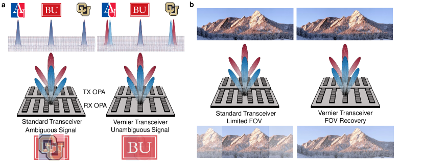
The improved performance of a Vernier OPA transceiver over the ‘standard’ transceiver design, using identical TX and RX OPAs, is shown in Fig. 1. The standard transceiver (center, left) uses periodic OPAs, here with both TX and RX OPAs having 6 gratings. The identical periodicity of both OPAs results in a far-field set of grating lobes (top) which is identical for both the transmitted intensity (red) and reception pattern (blue). A Vernier transceiver (center, right) has different grating pitches, here using the same TX OPA with 6 gratings whereas the RX OPA has 5 gratings. This results in two different far-field patterns, where for proper grating phases the TX and RX main (center) lobes are aligned where as their grating lobes to either side are not aligned.
One capability of a Vernier transceiver is to reduce the ambiguity created by grating lobes, shown schematically in Fig. 1a. A transceiver using identical TX and RX OPAs (left) projects a set of overlapping lobes into the far-field. A transmitted pulse would hit every location within the red lobes, scatter off the target, and can be received by the blue lobes. For our example targets, AU/BU/CU, this creates an ambiguous signal. This ambiguity is shown schematically at the bottom for the case of imaging these targets, where even though more power is received along the main lobe it is difficult to distinguish the desired target. This contrasts with the Vernier transceiver case, where the main lobes of the TX and RX OPAs overlap but the grating lobes are misaligned. This results in significantly less signal received from the targets sampled by the grating lobes, and a far less ambiguous signal.
The other desired capability of a Vernier transceiver is to increase the FOV beyond the grating lobe spacing, which limits the FOV for a standard transceiver. This capability is shown in Fig. 1b (left), where only the central portion of the scene can be imaged with a standard transceiver (the grating lobe-limited FOV). When attempting to image the scene past the limited FOV, the a lobe (which was previously a grating lobe) scrolls into the central FOV and becomes the effective main lobe, contributing a stronger signal than the lobe directed outside the central FOV. A Vernier transceiver (right) allows the same lobe to be used across the entire FOV due to the lobe alignment, ensuring the desired lobe is always distinguished from the other lobes.
3 Vernier Scheme Theoretical Analysis
We begin by analytically examining the most common geometry for integrated 2D OPAs: a 1D array of long, weak gratings (see for example [12, 4]). Wavelength-steering is used to control the emission angle along the gratings by using the dispersive nature of grating couplers. Along the orthogonal dimension, beam steering is achieved by preceding each grating with a phase shifter which allows arbitrary control of the gratings’ emission phases. We consider the case of designing an RX OPA for some given TX OPA, where we desire to maximally suppress the grating lobes using the Vernier effect. In this regard we will present the derivation from an ‘intuitive’ perspective; a full derivation is provided in the Supplemental Materials which arrives at the same conclusions.
Examination of the far-field patterns of both the TX and RX, and use of the reciprocity principle, allows us to calculate the optical efficiency for different angles. We calculate the improvement in ambiguity, SNR, and scan range of the Vernier arrangement by comparison to two reference cases: a standard incoherent detector, and identical TX/RX arrays. Additionally, we consider two distinct phase-steering functions, a ‘naive’ phase function and a FOV-recovering phase function, and demonstrate the latter allows for a full semi-circle FOV which, until now, has been limited to the grating lobe pitch.
As a final theory component, we address the question of recreating the optimal RX array conditions and phase steering functions in a 2D wavelength-steered OPA. Because the geometry along the Vernier dimension is not decoupled from the phase of each grating, the implementation of the phase steering functions in a 2D wavelength-steered OPA is non-trivial.
3.1 Grating Lobe Suppression with a Vernier Transceiver
Here we consider two 2D OPAs used as the TX and RX ends of a transceiver with gratings of width and spaced with pitch forming apertures of widths . For single-mode operation of the gratings, and negligible cross-talk between adjacent gratings, the aperture emission is separable and therefore we consider the 1-D case along the grating-orthogonal direction, denoted here as the -axis. Furthermore, we assume monochromatic input and excitation only of the in-plane electric field component; therefore we leave the polarization implicit and use the scalar wave equation approximation [17].
For simplicity we assume uniform emission across the width of the grating, such that the field at the grating interface can be accurately described by a normal plane wave impinging on a rectangular aperture with width . While the mode profile or full-field simulations can be used to calculate more accurate emission profiles, they do not affect grating lobe suppression (relative to the identical TX/RX case). Each grating is assumed to have an arbitrary (controlled) phase and identical amplitude, corresponding to a uniformly apodized aperture along the -dimension. It should be noted that most common apodization strategies, such as windowed Gaussians, will only increase sidelobe and grating lobe suppression, so we consider the ‘worst-case’ scenario of uniform/no apodization.
In most applications, both the number of gratings, array size, and grating pitch of the TX array have been limited by some external factors, e.g. number of controllable phase-shifters and minimum waveguide pitch to avoid cross-talk. We therefore restrict the RX array such that , , and .
We begin with the scalar effective aperture function for the TX array
| (1) |
Because we are interested in the angular distribution of the light to find the far-field radiation pattern, we take the spatial Fourier transform of the aperture which yields
| (2) |
where we have used the definition , dropped normalization factors, and identified as the spatial frequency of the Fourier transform.
We now use the principle of reciprocity [18] to identify the field which will be coupled into the RX array, a coherent receiver, as the field which the RX array would radiate if light is injected into the output of the array [3]. The RX array has similar effective aperture and angular distribution of radiation as the TX array with appropriate exchanging of subscripted variables
| (3) |
| (4) |
In the far-field regime, at angles near broadside (the direction normal to the chip plane), the Fraunhofer approximation can be used for both TX and RX arrays to convert the spatial frequency to a spatial coordinate on a plane at distance as . For a diffuse target in this plane with field reflectivity profile , the power received by the RX array can be written as
| (5) |
In order to suppress grating lobes, we need to minimize the portion of due to grating lobes; for a uniform-reflectivity target, theoretically perfect suppression can be achieved for each grating lobe individually by aligning the peak of the RX grating lobe with a null of the corresponding TX grating lobe. See supplementary materials for further details. This peak-null alignment is controlled by the difference in grating pitches , where for identical pitches (non-Verniered TX/RX pair) the peaks are always aligned and there is no grating lobe suppression. This identical TX/RX case provides a reference value with which we can compare the Vernier design to determine the extra suppression provided by the Vernier transceiver.
The sidelobe nulls of a single beam are spaced at intervals of in the angular domain. To align the peak of every th RX grating lobe with the th null of each corresponding (th) TX grating lobe then requires
| (6) |
which is automatically satisfied when . Considering as an example the case of , such that is the number of rows different between the TX and RX arrays, it can be seen that the first () grating lobe pair has the RX peak aligned with the null, the second () RX grating lobe is aligned to the null, and so on. Notably, while the detected power is identically null for each grating lobe pair in isolation regardless of the value of , the grating lobe suppression will not be perfect in realistic situations with non-uniform reflectivity and finite targets. Larger values of increase grating lobe suppression in realistic scenarios by further separating the grating lobe peaks.
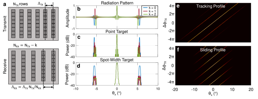
This choice of geometry, the corresponding radiation patterns, and detected power is shown in Fig. 2. In Fig. 2a we depict the restricted geometry, identical OPA widths but where the RX OPA has fewer gratings than the TX OPA, for an example 6-grating TX OPA and . The theoretical radiation patterns of the fabricated OPAs, discussed further in Sec. 4, are shown in Fig. 2b. This design uses a 32-grating TX OPA with 16 µm grating pitch and 6.5 µm wide gratings, which results in grating lobes at . The TX OPA radiation pattern (and identical RX OPA pattern for the , standard transceiver case) is shown in blue, while the RX OPA radiation pattern for a Vernier transceiver design with , is shown in red and blue respectively. The Vernier transceiver suppresses returns from the grating lobes to avoid signal ambiguity, which is depicted in Fig. 2c-d for broadside emission and plotted in terms of detected optical power. The point target case is shown in Fig. 2c, where the and Vernier transceivers have peak grating lobe returns 8.6 dB and 17.7 dB lower than the standard transceiver (). A uniform target which is exactly one spot width (Fig. 2d) will have grating lobe returns 17 dB and 20.8 dB lower than the standard transceiver.
3.2 Beam Steering with Vernier: Tracking and Sliding Vernier Steering
In addition to choosing the geometry of the TX and RX OPAs, there is also the question of steering a Vernier transceiver’s beam. The main lobes must remain aligned, corresponding to ideally misaligned grating lobes enforced by the geometry. Considering first a plane wave emitting from an aperture radiating to an angle relative to broadside, the phase-function in a the aperture plane is simply where . For an OPA, with discrete emitters, we steer the main lobe to the same angle by sampling this phase function at the emitter locations. For the th emitter the phase is then
| (7) |
and the phase difference between adjacent emitters is . Notably, because for our grating lobe suppression geometry, the phase difference between adjacent emitters is not identical between the TX and RX OPAs. Rather, the ‘phase rate’ is preserved in order to keep the main lobes aligned so that the RX lobe ‘tracks’ the corresponding TX lobe. As an alternative choice, one might maintain the same ‘phase step’ (phase difference ) for both TX and RX OPAs. This choice forces the main lobes to ‘slide’ into and out of alignment while the beam is steering such that two lobes are always aligned near broadside. We denote these two conditions as the tracking and sliding steering modes, both of which will be of interest in this paper for wavelength-steered OPAs. For an OPA with phase-shifter steering, only the tracking mode is desirable.
For the prescribed relation of grating pitches, we can write these two steering modes (tracking and sliding, respectively) as
| (8) |
These two steering modes are depicted in Fig. 2e-f, respectively, for the case. Notably, the tracking mode maintains lobe alignment at all angles, enabling the full FOV to be recovered as desired in addition to grating lobe suppression. The sliding mode does not expand the FOV beyond the grating lobe spacing, but does suppress grating lobes. Arbitrary steering modes, and discussion of the advantages of different steering modes in wavelength-steered OPAs, can be found in the supplementary materials.
3.3 Wavelength Beam Steering
With the generic beam steering functions determined, we are now interested in determining the more restrictive conditions of Vernier steering in wavelength-steered OPAs. The analysis of wavelength steering is linear for optical frequency and therefore we use the frequency rather than the wavelength to analyze wavelength-steering.
The simplest wavelength-steered OPAs uses an individual delay line input to each grating [2], with each successive delay line incrementally longer than the previous my some length . The phase of each grating is therefore tied to the wavelength via the delay line, allowing wavelength to be used to control the beam emission angle. For simplicity we assume all delay lines have identical effective and group indices , and we analyze the phase profile relative to a central frequency at which a lobe is emitted at broadside. For a frequency shift and small group velocity dispersion the phase step is then
| (9) |
Noting that the quantity is the group delay accumulated in the incremental length, we can write the phase step as simply
| (10) |
the product of the extra group delay and the frequency shift.
Using (8) we can find the relation of incremental lengths required in the wavelength steering case for tracking and sliding, respectively, as
| (11) |
For both of these relations, we could replace the incremental length with the incremental delay and find equally valid relations. Hence, since slow light waveguides can also be used to manipulate the steering (via the group index). One could also use the group index (with cross-section design) rather than length to produce the Vernier steering modes.
4 Serpentine Optical Phased Array
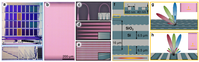
To demonstrate a Vernier transceiver, we use a 2D wavelength-steered OPA design demonstrated previously [3] which we call a serpentine OPA (SOPA). We fabricated an array of SOPAs, shown in Fig. 3a, of which two (highlighted) are used to demonstrate a Vernier transceiver with approximately 2 mm center-to-center spacing. Optical micrographs of the TX SOPA can be found in Fig. 3b-e, and design dimensions are shown in Fig. 3f. The SOPA routes the output of a grating to the input of the adjacent grating, thereby using the entire aperture has a single delay line. This is results in 2D wavelength-steering shown schematically in Fig. 3g-h where coarse wavelength shifts steer the beam along the grating dimension and fine wavelength shifts steer the beam along the grating-orthogonal dimension.
For the demonstration in this paper we designed a pair of SOPAs, one TX SOPA and one RX SOPA, to create a Vernier transceiver. The TX SOPA uses 6.5 µm wide waveguides for both the grating and flyback waveguides to achieve an ultra-low propagation loss (measured to be dB/cm) [3]. Our initial designs used a 16 µm grating-to-grating pitch to ensure minimal cross-talk, resulting in a grating lobe spacing. A variety of grating variants were fabricated; for this demonstration we use a silicon-sidewall grating with 50% duty cycle, 40 nm teeth, and 460 nm period (see Fig. 3f, inset). The TX SOPA has 32 gratings while the Rx SOPA has 31 gratings (), both approximately 800 µm long (sliding mode). A sliding mode was chosen to ensure a fully-populated FOV. See supplementary materials for additional discussion on implementation details for Vernier transceiver steering modes specific to SOPAs and design trade-offs.
5 Results
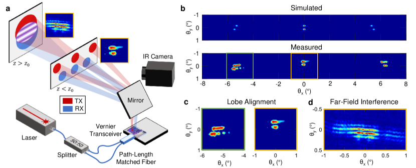
To demonstrate the Vernier transceiver, with and a sliding mode, we transmit from both TX and RX SOPAs simultaneously to measure their overlap patterns. The experimental setup is shown in Fig. 4a, where the radiation pattern is measured either in a ‘mid-field’ plane at approximately the Rayleigh range of a single aperture ( m) or in a far-field plane at a distance much greater than the Rayleigh range of the total, 3 mm long aperture. While the Rayleigh range of a single aperture can be easily accessed on a table top, the far-field plane of the composite aperture is approximately 20 m and we therefore use a Fourier lens to focused onto an IR detector to access the far-field plane.
The mid-field plane allows for easily distinguishable lobe alignment by simultaneously transmitting from both SOPAs, shown in Fig. 4b. The grating lobe spacing, as predicted by theory, is approximately . The lobes are slightly bleached by overexposure of the detector and we have applied a threshold to the image to suppress spurious noise. The increase in spot width over the simulated spot size is mainly a result of phase errors accumulated across the 6.4 cm path length of each SOPA. For additional details, see [3].
The mid-field plane allows one to see clearly see the alignment of the main lobes and misalignment of the grating lobes (Fig. 4c). However, the far-field plane is needed in order to accurately measure the overlap of the two lobes, which requires transmission from only one SOPA at a time. The overlap of the main lobes transmitted from both SOPAs in the far-field is shown in Fig. 4d, where the the high visibility and uniformity of the fringes demonstrates the high phase-coherence between the two SOPAs.
In this initial demonstration we did not measure LIDAR returns, so we calculate grating lobe suppression with a proxy metric, the overlap of the grating lobes. By transmitting from only the TX SOPA and measuring the far-field radiation pattern at each wavelength, and repeating this procedure for the RX SOPA, we measure the intensity distribution of each SOPA and calculate an overlap. Without direct access to the radiated field, only the intensity, we therefore calculate the intensity overlap of the radiated lobes and compare to the theoretical case. This intensity overlap is simply . This allows measurement of the grating lobe suppression (by proxy) and demonstration of the sliding mode implemented here.
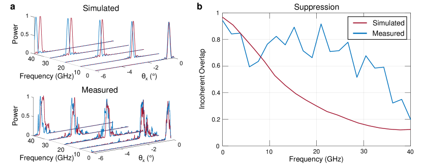
In Fig. 5 we demonstrate the sliding mode and grating lobe suppression. The sliding steering mode, discussed further in Sec. 3, ensures the main lobes are aligned at broadside but slide apart as they are scanned across the FOV. At the edge of the FOV, these two lobes have slide partially out of alignment; at the other edge of the FOV, two grating lobes are equally misaligned and will enter the FOV as the scan continues, becoming effectively the main lobes. As can be seen in Fig. 5a, the measured scanning pattern agrees well with predictions. While the imperfect radiation patterns partially obscure this sliding, the centroids of the spots are misaligned for the grating lobes (40 GHz). The desired suppression can be more easily seen by computing the intensity overlap for various frequency shifts, which agrees well with predictions for the main and grating lobes for the broadside emission case (main lobe at 0 GHz, grating lobe at 40 GHz). The increasing suppression with detuning demonstrates that the lobes slide out of alignment as they are scanned across the FOV, as desired. Notably, we measured an incoherent overlap as low as 20%, close to the theoretical value of 12%. This predicts a 6.4 dB grating lobe suppression (compared to 8.6 dB ideal suppression), to be verified in future work.
6 Discussion
These initial results indicate a Vernier transceiver is a promising approach to suppressing the ambiguous signals associated with grating lobes, and with improved designs can increase the FOV beyond the grating lobe spacing. The measured lobe suppression indicates the current demonstration is already useful for improving signal fidelity with regards to erroneous contributions from grating lobes. Additionally, this ambiguity suppression does not incur any additional loss for the return signal. By avoiding radiating out the power to all angles as with aperiodic OPA approaches [12], the Vernier transceiver can fully recover the signal while also avoiding the white noise background which inevitably results from aperiodic approaches.
The presented results are, however, very preliminary. Further work is needed to fully demonstrate grating lobe suppression by either directly measuring the radiated field or detecting a back-scattered signal for an imaging or LIDAR measurement. Such a setup would directly measure the suppression of grating lobes due to the Vernier transceiver as compared to a standard transceiver, whereas here we measure a proxy value – the incoherent overlap. Furthermore, higher grating lobe suppression can be achieved using a design, which will be the subject of later experiments. Notably, up to 18 dB of grating lobe suppression (21 dB for a large target) can be achieved with a design, increasing as increases. This is an order of magnitude higher than the theoretical suppression of 8.6 dB, and with the presented data indicating 6.4 dB of suppression it is reasonable to expect a design to achieve upwards of 15 dB suppression. The most important aspect of increasing grating lobe suppression, however, is improving spot quality so that lobe alignment/misalignment can better suppress erroneous returns. Future iterations of the SOPA will either include phase-shifters to correct for the fabrication variations which degrade the spot quality, or be smaller in size so as to be unaffected by these variations. Additionally, the low risk sliding design we demonstrate in this paper does not increase the FOV beyond the grating lobe spacing; future iterations will use Vernier transceivers with a tracking design so as to increase the FOV as discussed in Sec. 3. A tracking mode is particularly easy to implement in a phase-shifter steered OPA, and we expect that future demonstrations of Vernier transceivers in that subset of OPAs will use the tracking mode directly.
This paper presents a theoretical evaluation and experimental demonstration of a Vernier transceiver for reducing signal ambiguity and increasing FOV. We detail the optimal geometry for maximum grating lobe suppression, and the relative phases of emitters required to achieve different steering patterns. In particular, we discuss the non-trivial question of implementing a Vernier transceiver in 2D wavelength-steered OPAs and fabricate an example Vernier transceiver using our SOPA design. By simultaneously or alternately transmitting from a pair of SOPAs, we demonstrate alignment of main lobes at broadside, ensuring high signal detection, and misalignment of the grating lobes, ensuring rejection of erroneous signals. The measured spot patterns indicate up to 6.4 dB of grating lobe suppression, close to the theoretical value of 8.6 dB. Further improvements to the demonstrated design could suppress grating lobes by nearly 20 dB, and can widen the FOV up to the theoretical limit (the radiation pattern of a single emitter). We expect that Vernier transceivers will be a useful system-level design enabling improved OPA-based LIDARs and imagers, allowing these integrated photonic technologies to compete with traditional system designs.
Funding. U.S. Government; National Defense Science and Engineering Graduate Fellowship Program (NDSEG) (GS00Q14OADS139); National Science Foundation (NSF) (1144083); Packard Fellowship for Science & Engineering (2012-38222).
Acknowledgments. Portions of this work were presented at CLEO 2019 in the paper Vernier Si-Photonic Phased Array Transceiver for Grating Lobe Suppression and Extended Field-of-View, AW3K.2 [9]. Chip layout was carried out using an academic license of Luceda Photonics IPKISS.
See supplementary materials for supporting content.
References
- [1] H. Abediasl and H. Hashemi, “Monolithic optical phased-array transceiver in a standard soi cmos process,” Optics express, vol. 23, no. 5, pp. 6509–6519, 2015.
- [2] K. Van Acoleyen, W. Bogaerts, and R. Baets, “Two-dimensional dispersive off-chip beam scanner fabricated on silicon-on-insulator,” IEEE photonics technology letters, vol. 23, no. 17, pp. 1270–1272, 2011.
- [3] N. Dostart, B. Zhang, A. Khilo, M. Brand, K. A. Qubaisi, D. Onural, D. Feldkhun, K. H. Wagner, and M. A. Popović, “Serpentine optical phased arrays for scalable integrated photonic lidar beam steering,” Optica, vol. 7, pp. 726–733, Jun 2020.
- [4] C. V. Poulton, M. J. Byrd, P. Russo, E. Timurdogan, M. Khandaker, D. Vermeulen, and M. R. Watts, “Long-range lidar and free-space data communication with high-performance optical phased arrays,” IEEE Journal of Selected Topics in Quantum Electronics, 2019.
- [5] F. Aflatouni, B. Abiri, A. Rekhi, and A. Hajimiri, “Nanophotonic projection system,” Optics express, vol. 23, no. 16, pp. 21012–21022, 2015.
- [6] M. Raval, A. Yaacobi, D. Coleman, N. M. Fahrenkopf, C. Baiocco, G. Leake, T. N. Adam, D. Coolbaugh, and M. R. Watts, “Nanophotonic phased array for visible light image projection,” in 2016 IEEE Photonics Conference (IPC), pp. 206–207, IEEE, 2016.
- [7] R. Fatemi, B. Abiri, A. Khachaturian, and A. Hajimiri, “High sensitivity active flat optics optical phased array receiver with a two-dimensional aperture,” Optics express, vol. 26, no. 23, pp. 29983–29999, 2018.
- [8] H. A. Clevenson, S. J. Spector, L. Benney, M. G. Moebius, J. Brown, A. Hare, A. Huang, J. Mlynarczyk, C. V. Poulton, E. Hosseini, et al., “Incoherent light imaging using an optical phased array,” Applied Physics Letters, vol. 116, no. 3, p. 031105, 2020.
- [9] N. Dostart, M. Brand, B. Zhang, D. Feldkhun, K. Wagner, and M. A. Popović, “Vernier si-photonic phased array transceiver for grating lobe suppression and extended field-of-view,” in CLEO: Applications and Technology, pp. AW3K–2, Optical Society of America, 2019.
- [10] Y. Zhang, Y.-C. Ling, K. Zhang, C. Gentry, D. Sadighi, G. Whaley, J. Colosimo, P. Suni, and S. B. Yoo, “Sub-wavelength-pitch silicon-photonic optical phased array for large field-of-regard coherent optical beam steering,” Optics express, vol. 27, no. 3, pp. 1929–1940, 2019.
- [11] S. A. Miller, Y.-C. Chang, C. T. Phare, M. C. Shin, M. Zadka, S. P. Roberts, B. Stern, X. Ji, A. Mohanty, O. A. J. Gordillo, et al., “Large-scale optical phased array using a low-power multi-pass silicon photonic platform,” Optica, vol. 7, no. 1, pp. 3–6, 2020.
- [12] D. N. Hutchison, J. Sun, J. K. Doylend, R. Kumar, J. Heck, W. Kim, C. T. Phare, A. Feshali, and H. Rong, “High-resolution aliasing-free optical beam steering,” Optica, vol. 3, no. 8, pp. 887–890, 2016.
- [13] T. Komljenovic, R. Helkey, L. Coldren, and J. E. Bowers, “Sparse aperiodic arrays for optical beam forming and lidar,” Optics express, vol. 25, no. 3, pp. 2511–2528, 2017.
- [14] R. Fatemi, A. Khachaturian, and A. Hajimiri, “A nonuniform sparse 2-d large-fov optical phased array with a low-power pwm drive,” IEEE Journal of Solid-State Circuits, vol. 54, no. 5, pp. 1200–1215, 2019.
- [15] S. Pinna, B. Song, L. A. Coldren, and J. Klamkin, “Vernier transceiver architecture for side-lobe-free and high-entendue lidar,” in CLEO: Applications and Technology, pp. ATu3R–3, Optical Society of America, 2018.
- [16] C. T. Phare, M. C. Shin, S. A. Miller, B. Stern, and M. Lipson, “Silicon optical phased array with high-efficiency beam formation over 180 degree field of view,” arXiv preprint arXiv:1802.04624, 2018.
- [17] J. W. Goodman, Introduction to Fourier optics. Roberts and Company Publishers, 2005.
- [18] H. A. Haus, Waves and fields in optoelectronics. Prentice-Hall,, 1984.