∎
22email: drobin@kent.edu 33institutetext: S. Author 44institutetext: Kent State University, Kent, Ohio, USA
44email: javed@kent.edu
Toward an Abstract Model of Programmable Data Plane Devices
Abstract
SDN divides the networking landscape into 2 parts: control and data plane. SDN expanded it’s foot mark starting with OpenFlow based highly flexible control plane and rigid data plane. Innovation and improvement in hardware design and development is bringing various new architectures for data plane. Data plane is becoming more programmable then ever before. A common abstract model of data plane is required to develop complex application over these heterogeneous data plane devices. It can also provide insight about performance optimization and bench-marking of programmable data plane devices. Moreover, to understand and utilize data plane’s programmability, a detailed structural analysis and an identifiable matrix to compare different devices are required. In this work, an improved and structured abstract model of the programmable data plane devices is presented and features of its components are discussed in detail. Several commercially available programmable data plane devices are also compared based on those features.
Keywords:
Programmable data plane Abstract model Hardware abstraction layer P4 Software Defined Network (SDN)1 Introduction
From the very beginning, behavior of data plane devices were rigid and ruled by TCP/IP protocol stack. Different efforts Feamster:2014:RSI:2602204.2602219 for making this rigid environment more programmable haven’t gain momentum until OpenFlow protocol McKeown:2008:OEI:1355734.1355746 came to the theater. But, with it’s ever growing protocol field set, OpenFlow can not achieve the goal of real programmable network Bosshart:2014:PPP:2656877.2656890 . For true network programmability, data plane hardware architecture should be decoupled from protocol and programmable in nature. Various technologies openFlowSwitchSpecV135 ; ODP ; hoiland2018express ; dpdk ; VPP ; choi2018fboss ; SAI ; Bosshart:2013:FMF:2486001.2486011 ; Chole:2017:DDP:3098822.3098823 have been developed to program the run time behavior of a data plane device ‘on the fly’. They are becoming more computationally capable and various complex application layer processing tasks are being pushed to data plane Sivaraman:2017:HDE:3050220.3063772 ; Dang:2015:NCN:2774993.2774999 ; Kohler:2018:PTI:3229591.3229593 . This is enabling emergence of a new paradigm ‘in-network computation’ Sapio:2017:ICD:3152434.3152461 ; Benson:2019:ICC:3317550.3321436 . Enabling such cross layer behavior and protocol independence in data plane makes OSI layer based definition of switch (L2, L3, L4 switch etc.) obsolete. This raises the necessity of structured discussion on: how to define programmable switch/data plane device and how to define it’s programmability features? (Through rest of the paper, programmable switch and programmable data plane (PDP) device, these two terms are used interchangeably.)
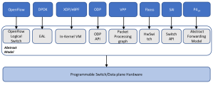
Programmable switch needs a software stack for programming the data plane. Abstraction layer (Device and resource Abstraction Layer (DAL) rfc7426 ) is one of the key component of these stacks. It provides a uniform view of the hardware and a convenient way to develop complex constructs rather than directly dealing with actual hardware instructions. Prominent programmable data plane technologies have heterogeneous hardware internals and corresponding hardware abstraction layer (HAL). They are different from each other (Fig. 1). But, without a common abstraction layer both data and control plane application become tightly bound to target architecture. For example, a program developed for RMT based architectures can not be executed directly over a DPDK based smart-NIC. Lack of common abstraction layer increases cost and complexity of development, testing, performance bench-marking and formal verification of any novel network functionality built over it. Besides this, a well designed hardware abstraction layer (Logical Forwarding Plane casado2010virtualizing ) is center piece for successful use of network virtualization, network function virtualization and service chain composition Casado:2014:ASN:2661061.2661063 . Though a common abstraction layer over heterogeneous hardware architecture has various advantages, but restricting to a single abstract model of hardware closes the door for future innovation in both hardware and abstraction layer design. PDP programming stacks should be decoupled from hardware architecture and capable of accommodating multiple hardware architecture.
Majority of the data plane programming stacks are tightly coupled with their own abstraction. Whereas, P4 (dominant data plane programming language) decoupled hardware architecture definition from packet processing behavior in it’s latest version (P416 p4v16 ). P416 provides separate language constructs to express abstract hardware architecture and develop program based on those architectures. Taking advantage of this feature, most of the data plane programming stacks have already developed interface with P4 choi2017pvpp ; voros2018t4p4s ; tu2018linux ; patra2017macsad ; switchsai ; shahbaz2016pisces . Besides this, several other architectures are also being proposed P4targets ; psaSpec ; Chole:2017:DDP:3098822.3098823 ; Rim:2018:HPP:3302425.3302435 ; he2018p4nfv . PSA psaSpec is one of the most matured among them. But majority of them lacks programmability of two important components: buffer and scheduler. Moreover, these hardware architecture definitions and how they process a packet are described in an informal language. It creates several issues. Most important among them are- I1) identifying clear definition of various components of a hardware architecture become hard I2) boundary between 2 components and how they connect with each other become unclear I3) exact details of how a packet is processed inside a component may differ from one hardware vendor to another I4) developing a formal structure or framework for data plane programs become hard. As consequence of I1) and I2), modular hardware/simulator/test-bed design become hard. As consequence of I3) application layer suffers. For example, if 2 hardware architecture not agree about packet processing states inside the components, taking snapshot of a network or testing/validating a data plane program for multiple architecture become extremely hard. As a result of I4), understanding and comparing various PDP devices and their programmability features become difficult. Moreover without a structural notion, formal analysis of data plane programs become hard. To tackle these challenges, a generalized but flexible yet abstract model of the programmable data plane is necessary. It should be modular in nature with well defined structure of the components. Besides this, well defined interface among the components are necessary for independent development and designing new packet processing architectures based on these components. Moreover, there should be a high level work flow of the components for ensuring uniform behavior across different hardware architectures.
Considering importance of an abstract model and current technology landscape, we think it is important to start discussion on a better model of abstraction layer for programmable switches. In this work, we have attempted to shed light on this topic. In doing so, we make a number of important contributions. After discussing background and related state of the art (in sec. 2), we provided a unified definition of programmable switch (in sec. 3) which is independent of any protocol stack. Then we presented the design of AVS, an example model of Device and resource Abstraction Layer (DAL)/Hardware Abstraction Layer (HAL) for programmable data plane devices (in sec. 4). It is modular in design and components are defined with a uniform and structured functional interface. In discussing details of the components (in sec. 5), at first a generic structure for the components with well defined type of pogrammability features (Compile Time Programmability (CTP) and Run Time Configurability (RTP)) are laid out. Then a detailed analysis of structure, workflow and progammability features of each components are discussed (in sec. 5.2 - 6.11). To present their workflow in a unambiguous and hardware independent manner, we have followed EFSM approach. After discussing components of AVS in details, a novel approach to compare programmability level of selected set of PDP devices based on programmability featues of AVS components are also presented (in sec. 7). We have also presented 4 important use cases of AVS (in sec. 8).
We do not claim the novelty of underlying components design. We are influenced by several existing work on this domain Bosshart:2013:FMF:2486001.2486011 ; 6665172 ; Mittal:2015:UPS:2834050.2834085 ; 8117533 ; Lin:2018:PRN:3185467.3185473 . We believe our achievement is providing a broader picture with an improved and structured abstract model for the programmable switches.
2 Background and Related Works
OpenFlow McKeown:2008:OEI:1355734.1355746 protocol is the most successful name in SDN paradigm. It is described over an abstract model of switch named ‘OpenFlow Logical Switch’ openFlowSwitchSpecV135 . OpenFlow decoupled control plane (CP) and data plane (DP). It provides limited programmability in data plane by controlling DP behavior from CP through dynamically configuring a broad set of protocol header fields. Soon academia and industry realized that, with it’s ever growing protocol field set OpenFlow can not achieve the goal of true programmable network. True potential of SDN can be leveraged only if data plane is fully programmable.
After the initial wave of OpenFlow based switches, work on programmable data plane device has gained significant momentum bifulco2018survey ; kaljic2019survey . The first consolidated effort for data-plane programmability can be attributed to RMT Bosshart:2013:FMF:2486001.2486011 , which proposed an architecture for programmable data plane devices. Based on RMT’s architecture, an ‘abstract forwarding model’ for data plane devices has been presented in Bosshart:2014:PPP:2656877.2656890 . In this work, authors have also presented a data plane programming language named P4 Bosshart:2014:PPP:2656877.2656890 to write program for RMT based programmable switches. Based on success of RMT and P4, several commercial programmable data plane devices has been emerged in the market BarefootTofino ; agilioCX . In initial version (version 14) of P4 (P414) p4v14 , data plane programs (DPP) were developed based on ‘abstract forwarding model’ of Bosshart:2014:PPP:2656877.2656890 . P414 was strictly coupled with the proposed abstract forwarding model. Although P414 came out with an abstract model and related programming construct to program them, it’s high cohesion with proposed hardware with limited programmability made it unsuitable for design of new data plane hardware architectures. This clearly shows the requirement of dis-aggregation between hardware architecture and programming language for programmable data plane devices.
Currently RMT is the dominant programmable data plane architecture. But it has few limitations. each pipeline stage of RMT architecture can only access memory allocated for it. As a result cross component access of memory/data is also not possible Chole:2017:DDP:3098822.3098823 . Moreover, as components of RMT pipeline are connected linearly, a packet can not skip unnecessary stages in the pipeline. To overcome these limitations, authors have proposed dRMT architecture in Chole:2017:DDP:3098822.3098823 . It improves RMT architecture by dis-aggregating memory and compute resources inside switch. In Rim:2018:HPP:3302425.3302435 authors presented a conceptual model of data plane for supporting parallel processing. It is heavily based on RMT and dRMT architecture. But these works, do not provide concrete hardware abstraction layer.
Efforts for making server based networking environment more programmable have also seen massive growth. DPDK dpdk and eBPF/XDP hoiland2018express are the two major framework for userspace and in-kernel packet processing. They rely on two abstraction layers: EAL for DPDK and in-kernel virutal machine for eBPF/XDP. Though they are able to work in conjunction with smart-NIC but they are not suitable for core switches. Another important category of programming stack is API based abstraction layer ODP ; SAI . Instead of providing an abstraction layer they provide an API through which data plane can be programmed. These APIs not provide any guideline about how to implement a feature. All conforming hardware vendors provide their own implementation of the API. As a result I3 (sec. 1) is not solved by API based solutions. Moreover to interface with data plane programming language (ex. P4), it needs more than one step. At first step, P4 codes are transformed to abstract API calls and then API calls are transformed to hardware specific instructions. Thus this style abstraction increases complexity.
Among all those data plane programming technologies, P4 and relevant tool-sets emerged as the most dominant programming stack. Nearly all the major programmable data plane platform have a P4 implementation or P4 interfacing choi2017pvpp ; voros2018t4p4s ; tu2018linux ; patra2017macsad ; switchsai ; shahbaz2016pisces . As P4 is becoming more matured, several works 188956 ; Dang:2017:WPL:3050220.3050231 ; Hancock:2016:HUP:2999572.2999607 ; 8038396 ; Liu:2018:PPV:3230543.3230582 ; Notzli:2018:PAT:3185467.3185497 ; Abhashkumar:2017:PPO:3050220.3050235 ; patra2017macsad ; he2018p4nfv focusing on various high level aspects of data plane is rolling out. But, as all of these works depends on P4, they are limited by the abstract forwarding model of P414 or few of the present hardware model P4targets supported by P416.
Initial version of P4 () was strictly coupled with the proposed ‘abstract forwarding model’ and RMT architecture. But later, P4 community have taken a clean state approach and followed the proven path of virtual machine world. In current version (version 16) of P4 (P416) p4v16 language constructs for expressing data plane device architecture and hardware specific features are decoupled from the constructs for expressing packet processing logic. Currently in a P416 based data plane program, developer needs to define a model of hardware (in form of include file) and the actual packet processing logic separately. This decoupling gives 4 crucial advantage: a) new hardware architecture can be supported any time b) common hardware architecture or abstraction layer can be created by all relevant stake holders c) top down design of programmable data plane hardware become possible d) high level language constructs for packet processing can be developed independently from hardware design . As a result, P4 can keep the path open for hardware innovation yet promoting interoperability through common hardware architectures. On the other hand P416 enables writing data plane behavior in a flexible and portable manner based on abstraction layers.
P4 community is actively working toward developing a common hardware architecture that can cover various programmable data plane devices ranging from core switches to smart-NIC. PSA psaSpec is the most matured attempt from P4 community toward that goal. It aims to list several common packet processing paths inside programmable switch and smart-NIC. These paths are composed from multiple programmable P4 blocks. It also lists several related stateful data structure and functions for use in data plane. PSA can be identified as the first structured effort toward a standard abstraction layer of data plane. But PSA specification describes the components and their work flow in a descriptive way. As a result there is always chance of confusion among various implementation of PSA and it suffers from problem I1,I2,I3 (section 1). Besides, PSA has no option of programmablity for buffer Lin:2018:PRN:3185467.3185473 and scheduler Mittal:2015:UPS:2834050.2834085 ; Sivaraman:2015:TPP:2834050.2834106 in the architecture. In this work, we intend to overcome these limitations by proposing a better abstract model (AVS) for programmable data plane devices by extending PSA architecture.
Our approach is aligned with P4 community, as the proposed abstract model (AVS) is inspired by PSA and P4. It also enhances the PSA architecture, firstly by adding programmability to buffer and scheduler components. Secondly, by providing a common functional structure for each components and expressing work flow of each components as hardware architecture agnostic extended finite state machine. These enhancements can help in designing various innovative applications (sec. 8 AVSTechReport )). Moreover, P4 doesn’t impose any restriction on use of hardware architecture and it has decoupled hardware dependent compiler back end for various architectures. Hence, use of AVS like abstract model doesn’t restrict use of other hardware architectures and the scope of innovation in hardware design remains wide open.
3 Programmable Switch
A packet ()’s life inside a switch starts with reaching through incoming (ingress) port as few bits of data and ends with exiting through outgoing (egress) port.
How a data plane device acts is defined by
-
•
S1- Interpreting Packet: how to interpret incoming set of bits () as different meaningful fields.
-
•
S2- Packet Metadata: a data plane device keeps few hardware dependent information about a packet (metadata) for use in different stages of the packet’s life cycle. Example: arrival time of a packet, this is necessary for packet scheduling.
-
•
S3- Packet Processing Work-flow: Set of operations executed based on different fields of packet and various data structures.
-
•
S4- Control Plane Configuration Parameters: data plane lacks of global knowledge about the network. Control plane needs to configure parameters so that S3 can be adapted with dynamic network conditions.
-
•
S5- Emitting Packet: What’s the structure of the packet emitted by the device.
In legacy switches, S1-S3 & S5 are static. Though S4 is available, they are rather configuring parameters for fixed S3. Hence, in legacy switches, once S1-S5 are loaded, they can’t be changed. These switches are optimized for specific protocol. But in programmable switch, S1-S5 are not static and they can be modified at switch lifetime. Formally, any combination of hardware and/or software is a programmable switch or programmable data plane device, if it fulfills following properties
-
•
P1: Not bound to any specific protocol
-
•
P2: Can execute any program, which
-
–
P2-1: contains logic and interface for S1-S5
-
–
P2-2: is not coupled to hardware architecture
-
–
P2-3: can be loaded and unloaded at runtime
-
–
Any logical abstraction that can provide an uniform view and functionality of a ‘programmable switch’ can be termed as an abstract model of programmable switch.
4 The Abstract Model (AVS)
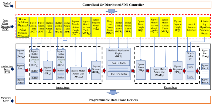
Processing path of a packet inside a programmable switch can be modeled as an abstract pipeline of serially connected programmable components. Our proposed pipeline based abstract model of programmable switch (‘Abstract Virtual Switch (AVS)’) is represented along with other components of SDN stack in Fig. 2. Components () of AVS are a) ingress port () b) ingress parser () c) ingress buffer engine () d) ingress match action unit () e) ingress deparser () f) buffer and replication engine () g) egress parser () h) egress match action unit () i) egress deparser () j) scheduler () k) egress port ().
Based on egress port selection for a packet, the AVS pipeline is logically divided into 2 stages: ingress stage- before selecting the egress port and egress stage- after selecting egress port. After entering egress stage a packet’s egress port can not be changed. This is particularly important when packets are replicated (clone, broadcast, multicast etc.) in egress stage. On such cases, packets may require further match action processing in egress stage. For example, traffic rate controlling at each outgoing port requires action at egress stage. If egress processing is not required in a hardware implementation, vendors may skip that part.
AVS may represent a single non virtualized programmable switch or a slice in a virtualized programmable switch or just a software switch. It is compiler’s duty to map components of AVS to actual hardware resources. AVS provides a uniform view of data plane over heterogeneous programmable switches. How the data plane will behave is defined by data plane program (DPP) (Fig. 2). Management plane handles (un)loading of DPP. On the other hand control plane controls runtime behavior of AVS by configuring parameters.
5 AVS Components
5.1 Generic Structure Of The Components
Each component () of AVS represents a programmable unit and they are needed to be programmed from outside before a packet processing starts. These are supplied as DPP. On the other hand CP controls each component’s behavior by configuring parameters through southbound interface. Degree of programmability of AVS and it’s components depend on following 2 kind of features.
-
•
Compile Time Programmability (CTP) Features: Set of instructions a programmable component can execute (comparable to cpu instruction set). How will behave at run time is defined through these features.
-
•
Run Time Configurability (RTC) Features: Capability of adjusting run-time behavior of CTP features through configuring parameters. Control plane uses these to manage the behavior of a component .
Irrespective of hardware implementation, CTP and RTC features can be exposed to upper layer as an uniform API. Compiler translates these API call to actual hardware instruction. DPP is a program expressed through CTP features and contains runtime processing logic of a component . And control plane application controls behavior of those processing logic at run time through features. DPP also contains data structures for facilitating control plane communication with through RTC features.
Formally, a component () can be represented as a component function ,
| (1) |
Here,
-
•
is the domain of , it represents the set of all possible values that accepts.
-
•
is the co-domain (range) of , it represents the set of all possible values that can return as output.
-
•
is the processing logic to be executed by the component. It is represented using , and control flow
-
•
is the input to the component,
-
•
is the output of the component, . If modifies and returns the result as variable of , notation is used. Ex. ingress match action unit (sec. 6.4)take as input and returns result as a modified .
-
•
is the set of parameters CP can configure to control the behavior of the component at run time. This is a subset of features
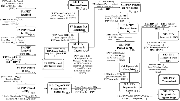
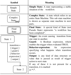
In next few subsections, each component of AVS are discussed in details. How they work and their programmability features are also discussed. For expressing work-flow of the components extended finite state machine (EFSM) approach is used. In figure 4, an EFSM is presented to define how a packet (PKT) goes through different components of the AVS. Separate sub state machines are used when necessary. Table 1 contains complex states of this state machine (figure 4) and reference to corresponding sub-state-machine with section number where the components are discussed. Notations used in the EFSMs are described in Fig. 3. Parser, match action unit and deparser exists both in ‘ingress’ and ‘egress’ stage. Their internal structure and parameters structures are same for both the stage but parameter names are different. To differentiate between ingress and egress stage components and parameters In and E subscripts are used respectively.
5.2 Related Terminology
Before driving into details of each component, few relevant terminologies and notations are discussed in this section.
5.2.1 Bit Space ( )
Upon receipt a packet () is a sequence of one and zero.
Formally, a packet () is a point in the space
.
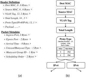
5.2.2 Header Definition ()
To do meaningful operation on a , it is needed to be interpreted as fields of different protocols. Header definition provides structure of these fields. Definition of i’th header field
Here,
Starting position of provides relative order of the field in packet. All together from packet header,
Rest of the packet is considered as payload.
5.2.3 Packet Metadata ()
Depending on actual hardware implementation, switches maintain some metadata () about a packet (ingress or egress port, time of arrival, packet unicast or multicast type etc.). I’th metadata field
Here,
All together from packet metadata,
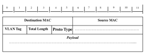
A sample packet format is shown in Fig. 5, corresponding header definition & a packet metadata are shown in Fig. 6. (a).
5.2.4 Packet Header Vector (PHV) and Space (PHVS)
Header definition and metadata defines a dimensional space named Packet Header Vector Space (PHVS). Each point in this space is termed as packet header vector (PHV). PHV can be considered as a container for all the attributes of a packet in key-value format. Where, key represents a header field () or metadata field () or any other field derived in the pipeline and value represents corresponding data.
Each PHV represents a point and flow represents a region in PHVS. In a PHV, all the fields in definition may not be present at some point in AVS. They may be filled up by different components in pipeline at different stage of the packet’s life-cycle.
5.2.5 Ordered PHV Set ()
Let is a set of . An ‘Ordered PHV Set’ is an ordered pair () of set and the binary relation contained in , such that
-
•
Reflexive:
-
•
Transitive:
-
•
Anti-symmetry:
Here the relation is defined based on one or more fields of such that, for a field
and 2 elements of the set ,
. If
then another filed can be used to break tie. As packets received from each port have distinct arrival time, and each port has different number in a switch, a total order on a set of is always possible.
Header Definition & Packet Metadata () together forms PHVS. Metdata is fixed for an architecture. PHVS is mainly dependent on Header definition. Nearly all the component’s of AVS domain and range is PHVS. Hence it is a crucial part of DPP.
6 Analysis of Components
6.1 Ingress Port ()
In AVS, sole task of an ingress port () is to receive a set of bits () and store as a PHV. How a hardware level frame is received and format of the frame is out of the scope of our discussion. After receiving, a new is initiated and is stored in data_buffer variable of PHV. data_buffer is a storage for an array of bits. In this phase, necessary metadata (ingress port, arrival time etc.) are also stored in the PHV. Then the is passed to next component in pipeline. In AVS, ingress ports do not have any kind of programmability in terms of and features.
6.2 Ingress Parser ()
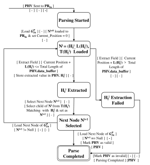
parses array of bits stored in to different header fields. Parsing logic is provided through parse graph (). Each node () contains: a) Header field information: to be parsed, starting position in and length of () and b) Parse table 6665172 ( (): Lists possible values of and corresponding next node. Work-flow of a programmable parser is shown in Fig. 7 as EFSM. After parsing, PHV is passed to next component in pipeline.
CTP features: a) maximum length limit: maximum length of that can be parsed by . This limit is important for bounded runtime. b) supported data types: different data types (including all the standard primitive data types: int, float, char etc) that can be supported by the parser c) granularity of field parsing: can the parser circuit parse individual bit or variable number number of bits to a field.
RTC features: a) modifiability of : is the parse graph () and it’s nodes contents are modifiable at runtime by CP.
6.3 Ingress Buffer Engine ()
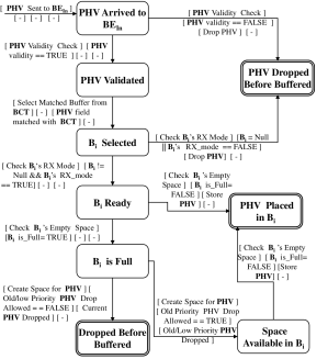
General role of a buffer is to temporarily hold packets. Though a programmable buffer can be expressed under match-action semantics, but its significance in various important applications Lin:2018:PRN:3185467.3185473 ; kogan2017programmable warrants a separate component for buffer. Ingress buffer engine () consists of a set of buffer (). Assuming individual buffers () in the engine, . Their size may be fixed or programmable. CP can control these sizes through configuring ‘Buffer Parameter Table ()’ (Table 3). There are 2 possible positions of in AVS. Any one or both can be used.
First one () is just after the . holds PHV received from ports. CP controls PHV from which ingress port should be stored to which buffer through ‘Buffer Configuration Table ()’.
Second one () is after ingress parser. This is a more generalized and useful implementation which can store PHV to a buffer based on PHV fields. Here, instead of only ingress port, CP configures based on which header/metadata field, a PHV should be sent to which buffer through ‘Buffer Configuration Table ()’ (Table 2). Priority for matching PHV’s also can be assigned through .
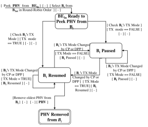
Buffer engine’s work-flow can be expressed as 2 threads: a) Receiver Thread (Fig. 8): for inserting PHV in buffers and b) Sender Thread (Fig. 9 ): for moving out PHV from buffers and sending to next component in pipeline. These 2 threads behavior are controlled by 2 separate state variable for each of the buffer (). These are configurable from control plane via ‘Buffer Parameter Table ()’. These 2 are: a) RX mode: when RX of a is true, receiver thread either receive PHV and store them (from port or ingress parser) or drop them if false b) TX mode: hold flow from buffer (buffer in pause state) when TX is false or release (buffer in resume state) packet/PHV to next component in pipeline when TX of the buffer () is true.
| PHV field Name | PHV field Value | Buffer ID | Priority |
|---|---|---|---|
| VLAN Tag | 0x 00 15 25 | 3 | 1 |
| VLAN Tag | 00 45 25 | 6 | 0 |
| Buffer ID | Size | RX | TX |
|---|---|---|---|
| 1 | 2048 | True | False |
| 5 | 3072 | False | True |
Receiver thread of buffer engine can be expressed as
and sender thread as (assuming a round-robin order for selecting next buffer from where next PHV will be peeked)
CTP features: a) buffer size & number controlling: number of buffers and corresponding size are programmable or not b) creation: is fixed or can be declared (size and definition) in compile time c) global access of buffer property: can other components of access buffer properties?
RTC features: a) BPT modifiability: can manipulate buffer size through b) modifiability: can add, modify or delete entry in table.
6.4 Ingress Match Action Unit ()
This component can be considered as the computational unit of a data plane device. What is cpu in a server, match-action unit can be considered as that unit for programmable data plane devices. Increasingly, more complex and generalized processing units (FPGA, CPU, GPU) are being proposed as the main computational unit for PDP devices. but match-action base hardware are still dominating. In this work, we have expressed the generic packet header based computations in match-action semantics. hardware implementations may use CPU/GPU/RMT circuit for implementing the actual logic. But the concept is generalized for the component.
In this component, values of field or any other data derived from them are matched with either a) control plane configured data or b) data collected by data plane itself. Based on matching result different actions are executed. Control plane configured data are kept in a table like data structure. Control plane can store, modify or delete data from these tables at runtime through southbound API. Data plane’s collected(or derived) data can be of 3 types a) stateful information about a flow(meter, register, counter etc.) b) stateless metadata about a packet and c) any constant value supplied at compile time in DPP.
Programmability and performance of a switch mostly depends on the set of actions it allows programmer to use. Actions can be of different types : stateless - only access and modify current PHV fields, stateful - access and update previously stored data about a flow and use them to to update PHV.
Different data plane programming language may represent match action semantics in different syntax. But fundamentally, match-action block requires 4 information, a) name/id of the PHV field which will be matched/compared b) control or data plane supplied value, against which PHV field values are matched or compared c) matching/comparison method (exact, ternary, <, > , != etc.) d) one or more action(action block) to execute based on comparison result.
| Match Type | Values to be Matched | Action[s] |
|---|---|---|
| Exact | 4 | Increase IPv4 counter |
| Exact | 6 | Drop Packet |
Without loosing generality, here we assumed that, storing computational logic for packet processing can be represented as graph. In current literature, generic data structure for storing processing logic information is termed as Bosshart:2013:FMF:2486001.2486011 . Processing logic for a match-action-unit can be represented as a match-action graph (), where each node() represents match-action logic for a specific field in PHV and edges are control flow. Let, a protocol field , it’s value in PHV is and data structure for storing it’s match-action information is .
. Corresponding is a tuple . Result of match-action processing for each field can be stored in stateful memory in case of stateful operations. Or they can simply update some fields in PHV(ex. updating destination port according to routing table). An example for ‘Proto Type’ field of sample packet (Figure 5) is presented in Table 4.
Let, = Set of for all the nodes() in . Formally ,
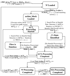
Work-flow of ingress match action unit() is presented in Fig. 10.
CTP features: a) data type support in MAT: data types (int, float, bit pattern, string etc.) allowed for lookup in MAT b) matching type support in MAT: type of look ups (longest prefix match, ternary, exact, range etc.) are supported c) MAT size & number controlling: MAT size are fixed length or their size can be declared in compile time d) availability of stateful action: is it possible to maintain state information about the flows e) availability of stateful data structure: what are the data structures for keeping state information about the flows (register, counter etc.). Custom data structure can be created or not f) state sharing among different components: are the flow states shareable among different components of AVS. g) MAT modifiability from DPP: is the MAT tables modifiable from the data plane program. This is necessary for advanced and faster decision making in data plane (Turkovic:2018:FNC:3229574.3229581, ). h) available action types: what are the different type of actions that can be done on the fields of a PHV.
RTC features: a) MAT controlling: can the CP add/ remove/update match-action tables entries b) stateful data access from CP: can the CP read/write stateful data of a flow from/to the DP.
6.5 Ingress Deparser()
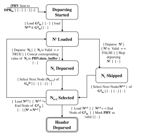
This component deserializes a . All the fields of a may not be necessary for emitting to next component. Some may be dropped or some may be included more than once. Moreover all the header fields declared in may not be valid for all the packets. In deparser definition, it is defined which of the valid header fields will be included in the outgoing packet. Besides the fields, constant data also can be included in the packet. Deparser definition is transformed to a graph() in compilation stage. In this graph each node represents a field of or any arbitrary data to be emitted. checks validity of each node and concatenates the field data in data_buffer(a per packet buffer for storing bits). This also inherently defines each fields relative position in the packet to be emitted. After deparsing all the nodes of , payload is concatenated to the data_buffer. Work-flow of an ingress deparser unit is represented as EFSM in Figure 11.
CTP features: a) maximum length limit: maximum length of a packet that can be created through the deparser unit b) data type support: data types that can be emitted by the deparser.
RTC features: a) modifiability: can CP modify at run time.
6.6 Buffer and Replication Engine()
is the bridge between ingress and egress stage. It contains buffer for each egress port. These buffers can be just simple FIFO buffer or fully programmable buffer (sec. 6.3 ). But header/metadata based buffer assignment of programmable buffer ( section 6.3) is not needed here, because we assume BRE buffers will be reserved as per port resource. Moreover, adding extra programmable circuit increases the packet processing delay.
For a , egress port selection is done in ingress match action unit. After ingress deparser, the PHV may be destined toward either a single egress port(unicast) or more than one egress port (manycast - multicast, broadcast).
-
•
For unicast port, PHV is simply moved to egress port’s buffer with all of its metadata.
-
•
For manycast port, control plane needs to configure group membership of the ports through ‘Manycast Group Table(MGT)’. BRE will make necessary number of copies of the PHV for each member of the group. Those PHV are placed to buffer of relevant egress ports.
Insertion of to port buffer () are handled by receiver thread of buffer. Sender thread of buffer removes from port buffer() and either drops or passes to egress stage. Work-flow of these 2 threads are same as of ingress buffer engine discussed in section 6.3.
Formally
Here, n = total number of egress port in a manycast group. For unicast packets n = 1.
CTP features: a) all of the features of (except )
RTC features: a) all of the features of (except configuration) b) Manycast group membership table configuration: can CP modify manycast group and their members at runtime.
6.7 Egress Parser ()
After PHV are removed from , they are sent to egress parser. Structurally it is same as ingress parser. Only difference is, after finishing egress parsing of packet header, instead of sending to a buffer, PHVs are sent to egress match-action unit.
6.8 Egress Match Action Unit ()
Same as ingress match action. Only restriction is, egress port can not be changed in this stage. Formally ,
6.9 Egress Deparser ()
Same as ingress deparser. Only difference is, after egress deparsing a PHV is sent to scheduler instead of buffer and replication engine.
6.10 Scheduler()
After egress processing is complete, a is passed to Scheduler() for transmission to next hop. Scheduling defines order and time Sivaraman:2015:TPP:2834050.2834106 of a PHV’s transmission. To achieve these goals, PHV is needed to be stored in specified order (according to scheduling algorithm) inside an appropriate scheduler data structure (SDS) (i.e. Queue, collection of queue, tree etc.). Different hardware implementation can use different data structure. From an abstract point of view, SDS maintains an ordered PHV Set (Section 5.2.5). From SDS PHV’s are selected according to scheduling algorithm for transmission at appropriate time. As there is no universal scheduling algorithm Sivaraman:2013:NSB:2535771.2535796 to match all kind of application goals, there is no common implementation of scheduler unit also.
To create a common and generalized abstract model, 2 abstract interfaces are assumed in conjunction with SDS. Different scheduling algorithm will implement these 2 interfaces differently based on data structures provided by the hardware. CP can adjust behavior of through configuring scheduling algorithm parameters(). Example: table for configuring weights of weighted fair queuing algorithm. These 2 abstract interface are following:
-
•
Insert(PHV): Implementation of this interface calculates the relative order of a inside SDS and places it in corresponding position. Let, is the metadata field that contains the PHV’s order in . Now assume, is a set of ordered by (in reality this order may depend in more than one field) stored in SDS.
Finding a new PHV()’s scheduling order requires computation of from following types of data.
-
–
value in ’s header fields() and/or metadata ()
-
–
stateful information about the flow, computed and stored by switch
-
–
CP configured parameter such as weight for a weighted fair queuing scheduling
Insert interface provides a total order (Section 5.2.5) on based on where,
Therefore, insert interface can be functionally represented as
Computing can be done either in match-action stage and result can be carried to scheduler unit through PHV. Or also can be computed in scheduler unit alone. After that, scheduler will insert the packet at appropriate location in the data structure. In case of storage shortage a low priority packet can be dropped or the packet in consideration itself can be dropped depending on scheduling algorithm.
-
–
-
•
Remove(): This interface’s implementation picks the next to be transmitted from and decides when the packet will be actually transmitted through .
CTP features: a) custom insert and remove interface: is it possible to provide implementation of these 2 interfaces for custom scheduling algorithm b) custom SDS creation: custom SDS can be created for complex scheduling algorithm or not c) cross component access: can other components in the pipeline access SDS (ex. clear a queue based on certain event detected at match action unit) or it’s properties (occupancy rate, priority etc.).
RTC features: a) insert and remove interface parameter modifiability: can the control plane configure parameters for controlling behavior of insert and remove functions b) SDS property access: can control plane access SDS properties c) controlling: can CP control scheduling algorithm parameters at run time.
6.11 Egress Port ()
After a PHV is selected for emitting, egress port () transmits the content of . How a hardware level frame is created and transmitted is out of the scope of our discussion. Like ingress ports, egress ports also do not have any kind of programmability in terms of and features.
| Application |
|
|
FlexPipe | Arista 7170 | Agilio CX | ||||||||
|
|
Parser and deparser | No | Yes | Yes | ||||||||
|
|
|
No | Partial | Yes | ||||||||
|
|
Scheduler | No | No | No | ||||||||
| Video streaming; | Manycast packet transfer |
|
Partial | Partial | Yes | ||||||||
|
|
|
Partial | Yes | Yes |
7 Programmability Level Comparison
PDP devices enables complex computation on packets in data plane. But limited memory, limited set of actions and requirement of maintaining line rate makes core switches unsuitable for complex algorithm. On the other hand, smart-NIC based packet processing in slow path (cpu based processing) provides opportunity for more complex computation. But achieving high speed line rate in such environments still remains a big issue. To understand what kind of algorithms can be implemented in data plane with available programmable switches in the current market, we have selected following representative platforms for comparison. FlexPipeflexpipeDatasheet is Intel’s Openflow supported programmable switching platform. It is selected as one of the early generation programmable switch of recent times. TofinoBarefootTofino is the most prominent and commercially successful programmable switching chip based on RMT architecture. It is being used by various switch vendors BarefootTofinoPartnerss . It’s various features are protected under barefoot non disclosure agreement. For comparison, we have chosen Arista 7170 arista7170 platform. It is based on Tofino chip and supports P416. Netronome Agilio Cx agilioCX (with 4000/6000 family NFP) is selected as a smnart-NIC based programmable switching platform. It can be programmed using micro-C and P4.
In table 5, we have listed few important types of algorithms, what are their crucial tasks that needs support from programmable switches (not achievable with traditional switches) and whether these tasks are supported by selected set of devices. From table 5, it is clear that, all the devices in the market are not equally programmable. To better understand their programmability level, we have scored those selected platforms in table 6 considering AVS components as base. Besides the selected programmable data plane platforms we have also included PSA psaSpec . PSA is the most matured switch architecture by P4 community and it is based on P416. AVS is also inspired by PSA. Until now, there is no hardware that follows full specification of PSA. But any architecture can be simulated in software level. Bmv2bmv2 is the reference implementation of P4, which can simulate various switch architectures including PSA. PSA is still not fully supported in bmv2. For comparison purpose, we assumed that PSA will support P416 and it will run on bmv2 simulation platform. Though PSA is still not realized, we believe comparison of existing hardware architecture with PSA (on bmv2) can give a clear picture of current state of the art. We have also included T-switch which represents most common category of traditional non-programmable L2/L3 switches for better understanding of the scores.
| , , , | |||||
| Features | |||||
| Component | Products | ||||
| Parser | FlexPipe | NA | 1 | NA | 1 |
| Arista 7170 | NA | 2 | NA | 2 | |
| Agilio Cx | NA | 2 | NA | 2 | |
| PSA | NA | 2 | NA | 2 | |
| T-switch | NA | 0 | 0 | 0 | |
| Ingress Buffer Engine | FlexPipe | 1 | 1 | 1 | 0 |
| Arista 7170 | 2 | 2 | 1 | 0 | |
| Agilio Cx | 2 | 2 | 2 | 2 | |
| PSA | NA | 2 | NA | NA | |
| T-switch | 0 | 0 | 0 | 0 | |
| Ingress Match Action Unit | FlexPipe | 1 | 1 | 1 | 1 |
| Arista 7170 | 2 | 2 | 2 | 3 | |
| Agilio Cx | 2 | 2 | 2 | 3 | |
| PSA | 2 | 2 | 2 | 3 | |
| T-switch | 0 | 0 | 0 | 0 | |
| Deparser | FlexPipe | 1 | 2 | NA | 1 |
| Arista 7170 | 2 | 2 | NA | 2 | |
| Agilio Cx | 2 | 2 | NA | 2 | |
| PSA | 2 | 3 | NA | 2 | |
| T-switch | 0 | 3 | NA | 0 | |
| Buffer & Replication Engine (BRE) | FlexPipe | 1 | 1 | 1 | 0 |
| Arista 7170 | 2 | 2 | 1 | 0 | |
| Agilio Cx | 2 | 2 | 2 | 2 | |
| PSA | 2 | 2 | 1 | 0 | |
| T-switch | 0 | 0 | 0 | 0 | |
| Scheduler | FlexPipe | 1 | 1 | 1 | 1 |
| Arista 7170 | 2 | 2 | 1 | 1 | |
| Agilio Cx | 2 | 2 | 2 | 3 | |
| PSA | 2 | 2 | 1 | 1 | |
| T-switch | 0 | 0 | 0 | 0 | |
Table 6, gives a 2-dimensional comparison among the selected platforms. Firstly, each component of AVS provides a specific type of programmablity in data plane. Comparing any platform on the basis of whether equivalent AVS components exists or not says whether equivalent functionality can be achieved in a platform or not. Secondly, eqn. 1 gives a functional structure for each of the component. Scoring the platforms based on parameters (, , and ) of this equation gives a fine grained view of each platform’s progammability level. Details comparison behind the scoring can be found in our full technical report AVSTechReport .
The scoring system is following: and represents some abstract data types.
-
•
NA- Programmability is not applicable here. Example: for all of the selected platforms, input () to ingress parser is a set of bits (). Programmability is not needed for input to an ingress parser.
-
•
0- The component is non programmable (ex. T-switch).
-
•
1- Selectable from a set of predefined data types. Example: FlexPipe flexpipeDatasheet hardware can only parse selected set of L2-L4 header fields.
-
•
2- New abstract data type (i.e. struct. class etc.) can be created. Example: in P4 supported devices, packet header definition can be created from struct, enum etc.
FOR :
-
•
NA- Programmability is not applicable here. Example: PSA has no provision for ingress buffer engine.
-
•
0- Non programmable component. Ex, traditional switch not supports any programmability for match-action units.
-
•
1- Only selectable from a set of pre-implemented logic /algorithm. Ex, in Flexpipe logic for match-action units are not programmable, only selectable from a predefined set of OpenFlow based actions.
-
•
2- New algorithms () can be implemented but stateful actions (any action that can fetch and store a flow state) not supported. Ex. parser of P4 supported switches can be programmed to parse headers but no stateful memory is not available here .
-
•
3- New algorithms () can be implemented with stateful actions support. Ex. P4 supported switches can perform action and store results in counter or register.
8 Motivating Use Cases
Abstraction plays very important role in SDN rfc7426 . Abstractions used in SDN are hierarchical in nature and used in different layers Casado:2014:ASN:2661061.2661063 . Hardware abstraction layer is placed over programmable hardware layer and provides a uniform view to other layers (‘Device and resource Abstraction Layer (DAL)’ rfc7426 ). As an instance of hardware abstraction layer, AVS hides low level hardware complexity and it can provide a uniform view of hardware layer to both control plane and data plane application. Hence its use cases can be found in every aspect of a truly programmable data plane device. We are mentioning few important use cases here.
8.1 Modular Architecture Design & Development
Modular architecture design is the goal of good design. But majority of the programmable data plane architecture in literature are expressed in informal language. This makes modular design harder for 3 major reasons: a) lack of clear description about the role of a component b) lack of clear boundary between 2 components c) how the components connect with each other in pipeline. These shortcomings create bottleneck in independent design and optimization of components. It also brings disadvantages in designing new pipeline based on reuse of those components. A modular abstraction layer can solve these issues.
Consider a PDP architecture, where boundary between Ingress Buffer Engine () and Ingress Match Action Unit () is not clear . As both the components have match-action semantics, can be designed as a part of . After header matching, storing in and removing packet from buffer can be designed as one of the actions of . Now, consider a smart-NIC based packet processing architecture, where packets are moved to userspace and processed in CPU and/or GPU. Also assume is implemented on CPU and GPU . GPUs perform better in parallel and batch processing, where buffering is a per packet processing task not best suitable for GPU. Implementing buffer engine as part of match-action unit using GPU needs costly data transfer to and from memory to GPU. Or for smart-NIC based environments packets are needed to be moved from smart-NIC buffer to GPU. This data movement often loses the GPU performance gain. Hence it is better to implement buffer engine as a separate component. If buffer engine functionality is merged with optimal hardware performance can not be achieved in this case. In this example, if AVS like abstraction layer is used, data plane application developers can write logic without thinking about underlying CPU and/or GPU based implementation. AVS components to actual hardware mapping is done by the compilers. Thus tasks of can be executed on CPU only and can be mapped to CPU and/or GPU depending on performance goal. Moreover, new hardware (ex. specialized chip or FPGA) can be designed and optimized independently for each of the components.
8.2 Virtualization & New Pipeline Design
Equation 1 provides a structured framework for each component. It clearly defines the input, output, packet processing logic and parameters for how to configure run-time behavior of a component through control plane (). Communication among the components is only through passing parameters. It removes control dependency among components. This gives several advantages: a) AVS gives a hardware independent and portable representation of data plane device which can be used to slicing the hardware layer b) DPPs can be developed based on machine model provided by AVS c) AVS can be used to create a virtual switch (VM like entity) for data plane d) switch hypervisor like entities can execute or migrate same DPP to different hardware architecture.
Consider a smart-NIC based scenario where the datapath is moved to userspace using DPDK. Also assume, the data plane prorgam (DPP) is assigned to do both IPv4/6 packet processing and running an algorithm for accelerating ML algorithms through in network aggregation technique sapio2019scaling ; wang2019high . Aggregation is basically mathematical processing and computationally expensive which can be executed in parallel fashion. Let, IPv4/6 packet processing is expressed as and aggregation based packet processing logic is expressed as . Now, to make packet aggregation faster, is assigned to be executed on GPU. And IPv4/6 packet processing ( ) tasks are executed on CPU. Also assume, CPU can process 1 IPv4/6 packet in 1 cycle where as GPU can aggregate 10 packets in a single cycle and produce result of aggregation as one packet. As CPU and GPU run in different speed, synchronizing and scheduling the packet processing over them is very important. Without a clear definition and structure of and , synchronizing packet processing over CPU and GPU is not possible. Moreover based on underlying server capability number of CPU cores may differ and GPUs may not be available at certain time. To handle these kind of scenarios, a VM like entity for data plane is mandatory. AVS can works as a virtual switch for data plane.Moreover, modular representation provided by AVS, can also enable switch hypervisors to assign and synchronize execution of DPP over various types of hardware.
8.3 Testing & Verification
Earlier data plane devices were mainly designed for executing network protocol. But in programmable data plane devices, more and more application layers tasks are pushed toward data plane. These devices can be loaded with new data plane program at any period of their life time. Testing them or validating some property at run time over these programs are very important. Without a common abstraction layer and workflow, testing programs and verifying properties over heterogeneous hardware architecture increases the cost and complexity. To write test cases, a common set of packet processing state among switches are required. Without a common abstraction layer and a common set of packet processing states, how various hardware vendors implements packet processing logic can differ.
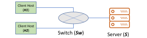
Consider client-server scenario of Fig. 12. At a certain time H1 got disconnected from server (S) due to H1-Sw link failure. Detecting the link failure switch (Sw) stores all packets directed for H1 in of ingress buffer engine (section 6.3) . When becomes full, Sw sends a notification to controller. Upon receiving this notification, controller initiates migration of the whole network (migration including switch state a packet stored in buffer Keller:2012:LME:2390231.2390250 ) from one data center to another. Clearly, this kind of DPP depends on the " is Full" state of buffer receiver thread (sec. 6.3, Fig. 8). For testing them and ensuring uniform behavior, switch vendor of both the data center need to support ingress buffer engine with common packet processing states. Use of AVS as an abstraction layer provides a common abstract switch over heterogeneous architecture and DPP developer gets a uniform view of the hardware. Moreover AVS expresses behavior of the components through EFSM. Common abstraction of the components and common set of packet processing states of the components can be leveraged together to write portable code and testing them.
8.4 Network Function Modeling
Eq. (1) enables representation of each components of AVS in a uniform and hardware independent manner. Composing for all the components and concatenating them represents AVS as a transfer function () (180587, ). Compiler translates this functional representation to hardware instruction. Any network function (NF) programmed on AVS can be expressed as , where , , , are different for each NF . Each link of a network transfers a from one hop to another. Link also can be represented as a function () of same structure.
can be considered as the functional representation of data link layer. Depending on medium, corresponding
(i.e. ring/mesh/star networks, CSMA, CSMA/ CD etc.) and (i.e. persistent level for CSMA) can be different. Based on these, a ’s transmission and propagation delay can be different. These delays can be derived from time stamp (passed as ) at sender node and receiver node. Again applying and a whole network topology can be represented as a topology function () 180587 . These functional representation are based on abstraction layer and they are hardware independent representation with well defined parameters for each component. This kind of representation provides various benefits. Few of them are
-
•
Network algebra: Network algebra is an old and deeply studied topics. With rise of programmable data plane device, it is more relevant and applicable for today’s network. Expressing network functions and networks in a functional paradigm allows usage of formal methods of network algebra Anderson:2014:NSF:2578855.2535862 180587 .
-
•
Network Delay Modeling: Time-stamping 7562197 packet in data plane is a strong concept with many usage mymb-sfc-nsh-allocation-timestamp-05 . But maintaining time-stamp only at entry and exit point of a switch can’t provide deep information about various type of delay. Time-stamp can be maintained at entry () and exit () point of each component in packet metadata (). Delay inside a component () can be calculated as
Thus, fine grained information about various delay can be collected. One of the most simple but powerful model of delay is Network Delay. It can be computed as following
Complex data plane processing with time stamp can be used for further complex measurement of various types of delay categorized by source 6967689 .
9 Conclusion
In this work, we proposed the design of AVS, a modular hardware abstraction layer for programmable data plane devices. We are working on a bmv2 bmv2 based implementation of AVS. Our work on representing components of abstraction layer for data plane devices with a well defined functional structure and their work flow in EFSM can provide a strong base for optimizing, bench marking and comparing different programmable data plane devices. We invite research community to investigate how to improve this formal structure and develop frameworks for using it. We have also analyzed the programmability features of different components and compared few important products based on them. Deriving formal relation between what set of programmability features can support a specific class of algorithms in data plane can be a promising research direction. Besides this, designing chip directly from abstract model also can be a very promising research scope.
References
- (1) Abhashkumar, A., Lee, J., Tourrilhes, J., Banerjee, S., Wu, W., Kang, J.-M., and Akella, A. P5: Policy-driven optimization of p4 pipeline. In Proceedings of the Symposium on SDN Research (New York, NY, USA, 2017), SOSR ’17, ACM, pp. 136–142.
- (2) Anderson, C. J., Foster, N., Guha, A., Jeannin, J.-B., Kozen, D., Schlesinger, C., and Walker, D. Netkat: Semantic foundations for networks. SIGPLAN Not. 49, 1 (Jan. 2014), 113–126.
- (3) Benson, T. A. In-network compute: Considered armed and dangerous. In Proceedings of the Workshop on Hot Topics in Operating Systems (New York, NY, USA, 2019), HotOS ’19, ACM, pp. 216–224.
- (4) Bifulco, R., and Rétvári, G. A survey on the programmable data plane: Abstractions architectures and open problems. In Proc. IEEE HPSR (2018), pp. 1–7.
- (5) Bosshart, P., Daly, D., Gibb, G., Izzard, M., McKeown, N., Rexford, J., Schlesinger, C., Talayco, D., Vahdat, A., Varghese, G., and Walker, D. P4: Programming protocol-independent packet processors. SIGCOMM Comput. Commun. Rev. 44, 3 (July 2014), 87–95.
- (6) Bosshart, P., Gibb, G., Kim, H.-S., Varghese, G., McKeown, N., Izzard, M., Mujica, F., and Horowitz, M. Forwarding metamorphosis: Fast programmable match-action processing in hardware for sdn. In Proceedings of the ACM SIGCOMM 2013 Conference on SIGCOMM (New York, NY, USA, 2013), SIGCOMM ’13, ACM, pp. 99–110.
- (7) Briscoe, B., Brunstrom, A., Petlund, A., Hayes, D., Ros, D., Tsang, I., Gjessing, S., Fairhurst, G., Griwodz, C., and Welzl, M. Reducing internet latency: A survey of techniques and their merits. IEEE Communications Surveys Tutorials 18, 3 (thirdquarter 2016), 2149–2196.
- (8) Casado, M., Foster, N., and Guha, A. Abstractions for software-defined networks. Commun. ACM 57, 10 (Sept. 2014), 86–95.
- (9) Casado, M., Koponen, T., Ramanathan, R., and Shenker, S. Virtualizing the network forwarding plane. In Proceedings of the Workshop on Programmable Routers for Extensible Services of Tomorrow (2010), ACM, p. 8.
- (10) Choi, S., Burkov, B., Eckert, A., Fang, T., Kazemkhani, S., Sherwood, R., Zhang, Y., and Zeng, H. Fboss: building switch software at scale. In Proceedings of the 2018 Conference of the ACM Special Interest Group on Data Communication (2018), ACM, pp. 342–356.
- (11) Choi, S., Long, X., Shahbaz, M., Booth, S., Keep, A., Marshall, J., and Kim, C. Pvpp: A programmable vector packet processor. In Proceedings of the Symposium on SDN Research (2017), ACM, pp. 197–198.
- (12) Chole, S., Fingerhut, A., Ma, S., Sivaraman, A., Vargaftik, S., Berger, A., Mendelson, G., Alizadeh, M., Chuang, S.-T., Keslassy, I., Orda, A., and Edsall, T. drmt: Disaggregated programmable switching. In Proceedings of the Conference of the ACM Special Interest Group on Data Communication (New York, NY, USA, 2017), SIGCOMM ’17, ACM, pp. 1–14.
- (13) Consortium, P. L. Behavioral model version 2, 2017.
- (14) Consortium, P. L. Switchsai, Dec 21, 2016.
- (15) Consortium, T. P. L. The p4 language specification version 1.0.4, 2017.
- (16) Consortium, T. P. L. P4 16 language specification:version 1.1.0, 2018.
- (17) Consortium, T. P. L. Behavioral model targets, 2019.
- (18) Corporation, N. D. I. Intel ethernet switch fm5000/fm6000(datasheet), 2017.
- (19) Dang, H. T., Sciascia, D., Canini, M., Pedone, F., and Soulé, R. Netpaxos: Consensus at network speed. In Proceedings of the 1st ACM SIGCOMM Symposium on Software Defined Networking Research (New York, NY, USA, 2015), SOSR ’15, ACM, pp. 5:1–5:7.
- (20) Dang, H. T., Wang, H., Jepsen, T., Brebner, G., Kim, C., Rexford, J., Soulé, R., and Weatherspoon, H. Whippersnapper: A p4 language benchmark suite. In Proceedings of the Symposium on SDN Research (New York, NY, USA, 2017), SOSR ’17, ACM, pp. 95–101.
- (21) Feamster, N., Rexford, J., and Zegura, E. The road to sdn: An intellectual history of programmable networks. SIGCOMM Comput. Commun. Rev. 44, 2 (Apr. 2014), 87–98.
- (22) Foundation, L. Data plane development kit, 2018.
- (23) FOUNDATION, O. Open data plane (odp).
- (24) FOUNDATION, O. Vector packet processing (vpp).
- (25) Foundation, O. N. Openflow switch specification: Version 1.3.5, 2015.
- (26) Gibb, G., Varghese, G., Horowitz, M., and McKeown, N. Design principles for packet parsers. In Architectures for Networking and Communications Systems (Oct 2013), pp. 13–24.
- (27) Group, T. P. A. W. P416 portable switch architecture (psa)(working draft), 2018.
- (28) Haleplidis, E., Pentikousis, K., Denazis, S., Salim, J. H., Meyer, D., and Koufopavlou, O. Software-Defined Networking (SDN): Layers and Architecture Terminology. RFC 7426, Jan. 2015.
- (29) Hancock, D., and van der Merwe, J. Hyper4: Using p4 to virtualize the programmable data plane. In Proceedings of the 12th International on Conference on Emerging Networking EXperiments and Technologies (New York, NY, USA, 2016), CoNEXT ’16, ACM, pp. 35–49.
- (30) He, M., Basta, A., Blenk, A., Deric, N., and Kellerer, W. P4nfv: An nfv architecture with flexible data plane reconfiguration. In 2018 14th International Conference on Network and Service Management (CNSM) (2018), IEEE, pp. 90–98.
- (31) Høiland-Jørgensen, T., Brouer, J. D., Borkmann, D., Fastabend, J., Herbert, T., Ahern, D., and Miller, D. The express data path: Fast programmable packet processing in the operating system kernel. In Proceedings of the 14th International Conference on Emerging Networking EXperiments and Technologies (2018), ACM, pp. 54–66.
- (32) Jose, L., Yan, L., Varghese, G., and McKeown, N. Compiling packet programs to reconfigurable switches. In 12th USENIX Symposium on Networked Systems Design and Implementation (NSDI 15) (Oakland, CA, 2015), USENIX Association, pp. 103–115.
- (33) Kaljic, E., Maric, A., Njemcevic, P., and Hadzialic, M. A survey on data plane flexibility and programmability in software-defined networking. IEEE Access 7 (2019), 47804–47840.
- (34) Kazemian, P., Varghese, G., and McKeown, N. Header space analysis: Static checking for networks. In Presented as part of the 9th USENIX Symposium on Networked Systems Design and Implementation (NSDI 12) (San Jose, CA, 2012), USENIX, pp. 113–126.
- (35) Keller, E., Ghorbani, S., Caesar, M., and Rexford, J. Live migration of an entire network (and its hosts). In Proceedings of the 11th ACM Workshop on Hot Topics in Networks (New York, NY, USA, 2012), HotNets-XI, ACM, pp. 109–114.
- (36) Kogan, K., Menikkumbura, D., Petri, G., Noh, Y., Nikolenko, S., Sirotkin, A., and Eugster, P. A programmable buffer management platform. In 2017 IEEE 25th International Conference on Network Protocols (ICNP) (Oct 2017), pp. 1–10.
- (37) Kogan, K., Menikkumbura, D., Petri, G., Noh, Y., Nikolenko, S., Sirotkin, A., and Eugster, P. A programmable buffer management platform. In 2017 IEEE 25th International Conference on Network Protocols (ICNP) (2017), IEEE, pp. 1–10.
- (38) Kohler, T., Mayer, R., Dürr, F., Maaß, M., Bhowmik, S., and Rothermel, K. P4cep: Towards in-network complex event processing. In Proceedings of the 2018 Morning Workshop on In-Network Computing (New York, NY, USA, 2018), NetCompute ’18, ACM, pp. 33–38.
- (39) Lin, Y., Kozat, U. C., Kaippallimalil, J., Moradi, M., Soong, A. C., and Mao, Z. M. Pausing and resuming network flows using programmable buffers. In Proceedings of the Symposium on SDN Research (New York, NY, USA, 2018), SOSR ’18, ACM, pp. 7:1–7:14.
- (40) Liu, J., Hallahan, W., Schlesinger, C., Sharif, M., Lee, J., Soulé, R., Wang, H., Caşcaval, C., McKeown, N., and Foster, N. P4v: Practical verification for programmable data planes. In Proceedings of the 2018 Conference of the ACM Special Interest Group on Data Communication (New York, NY, USA, 2018), SIGCOMM ’18, ACM, pp. 490–503.
- (41) Malloy, D., Maltz, D., Williams, C., Manickam, A. S., Daparthi, A., Wichmann, C., Lazar, M., Sane, S., Baldonado, O., Fang, T., Simpkins, A., Gale, B., Cummings, U., Daly, D., Penner, M., Kadosh, M., Baz, I., and Raveh, A. Switch abstraction interface v0.9.2, 2015.
- (42) McKeown, N., Anderson, T., Balakrishnan, H., Parulkar, G., Peterson, L., Rexford, J., Shenker, S., and Turner, J. Openflow: Enabling innovation in campus networks. SIGCOMM Comput. Commun. Rev. 38, 2 (Mar. 2008), 69–74.
- (43) Mittal, R., Agarwal, R., Ratnasamy, S., and Shenker, S. Universal packet scheduling. In Proceedings of the 14th ACM Workshop on Hot Topics in Networks (New York, NY, USA, 2015), HotNets-XIV, ACM, pp. 24:1–24:7.
- (44) Mizrahi, T., and Moses, Y. The case for data plane timestamping in sdn. In 2016 IEEE Conference on Computer Communications Workshops (INFOCOM WKSHPS) (April 2016), pp. 856–861.
- (45) Mizrahi, T., Yerushalmi, I., Melman, D. T., and Browne, R. Network Service Header (NSH) Context Header Allocation: Timestamp. Internet-Draft draft-mymb-sfc-nsh-allocation-timestamp-05, Internet Engineering Task Force, Oct. 2018. Work in Progress.
- (46) NETRONOME. Agilio cx smartnics, 2018.
- (47) Networks, A. Arista 7170 series, 2018.
- (48) Networks, B. Barefoot partners, 2018.
- (49) Networks, B. Barefoot tofino, 2019.
- (50) Nötzli, A., Khan, J., Fingerhut, A., Barrett, C., and Athanas, P. P4pktgen: Automated test case generation for p4 programs. In Proceedings of the Symposium on SDN Research (New York, NY, USA, 2018), SOSR ’18, ACM, pp. 5:1–5:7.
- (51) Patra, P. G., Rothenberg, C. E., and Pongracz, G. Macsad: High performance dataplane applications on the move. In 2017 IEEE 18th International Conference on High Performance Switching and Routing (HPSR) (2017), IEEE, pp. 1–6.
- (52) Rim, S. Y., Cui, Z., and Qian, L. High performance packet processor architecture for network virtualization: Programmable packet processor architecture as a data flow machine. In Proceedings of the 2018 International Conference on Algorithms, Computing and Artificial Intelligence (New York, NY, USA, 2018), ACAI 2018, ACM, pp. 6:1–6:5.
- (53) Robin, D. D., and I.Khan, D. J. Toward an abstract model of programmable data plane devices (technical report).
- (54) Sapio, A., Abdelaziz, I., Aldilaijan, A., Canini, M., and Kalnis, P. In-network computation is a dumb idea whose time has come. In Proceedings of the 16th ACM Workshop on Hot Topics in Networks (New York, NY, USA, 2017), HotNets-XVI, ACM, pp. 150–156.
- (55) Sapio, A., Canini, M., Ho, C.-Y., Nelson, J., Kalnis, P., Kim, C., Krishnamurthy, A., Moshref, M., Ports, D. R., and Richtárik, P. Scaling distributed machine learning with in-network aggregation. arXiv preprint arXiv:1903.06701 (2019).
- (56) Shahbaz, M., Choi, S., Pfaff, B., Kim, C., Feamster, N., McKeown, N., and Rexford, J. Pisces: A programmable, protocol-independent software switch. In Proceedings of the 2016 ACM SIGCOMM Conference (2016), ACM, pp. 525–538.
- (57) Sivaraman, A., Subramanian, S., Agrawal, A., Chole, S., Chuang, S.-T., Edsall, T., Alizadeh, M., Katti, S., McKeown, N., and Balakrishnan, H. Towards programmable packet scheduling. In Proceedings of the 14th ACM Workshop on Hot Topics in Networks (New York, NY, USA, 2015), HotNets-XIV, ACM, pp. 23:1–23:7.
- (58) Sivaraman, A., Winstein, K., Subramanian, S., and Balakrishnan, H. No silver bullet: Extending sdn to the data plane. In Proceedings of the Twelfth ACM Workshop on Hot Topics in Networks (New York, NY, USA, 2013), HotNets-XII, ACM, pp. 19:1–19:7.
- (59) Sivaraman, V., Narayana, S., Rottenstreich, O., Muthukrishnan, S., and Rexford, J. Heavy-hitter detection entirely in the data plane. In Proceedings of the Symposium on SDN Research (New York, NY, USA, 2017), SOSR ’17, ACM, pp. 164–176.
- (60) Tu, W., Ruffy, F., and Budiu, M. Linux network programming with p4. In Linux Plumbers’ Conference 2018 (2018).
- (61) Turkovic, B., Kuipers, F., van Adrichem, N., and Langendoen, K. Fast network congestion detection and avoidance using p4. In Proceedings of the 2018 Workshop on Networking for Emerging Applications and Technologies (New York, NY, USA, 2018), NEAT ’18, ACM, pp. 45–51.
- (62) Vörös, P., Horpácsi, D., Kitlei, R., Leskó, D., Tejfel, M., and Laki, S. „t4p4s: A target-independent compiler for protocolindependent packet processors”. In IEEE HPSR (2018), pp. 17–20.
- (63) Wang, S.-Y., Wu, C.-M., Linm, Y.-B., and Huang, C.-C. High-speed data-plane packet aggregation and disaggregation by p4 switches. Journal of Network and Computer Applications (2019).
- (64) Zhang, C., Bi, J., Zhou, Y., Dogar, A. B., and Wu, J. Hyperv: A high performance hypervisor for virtualization of the programmable data plane. In 2017 26th International Conference on Computer Communication and Networks (ICCCN) (July 2017), pp. 1–9.