High-fidelity controlled-Z gate with maximal intermediate leakage operating at the speed limit in a superconducting quantum processor
Abstract
We introduce the sudden variant (SNZ) of the Net Zero scheme realizing controlled- (CZ) gates by baseband flux control of transmon frequency. SNZ CZ gates operate at the speed limit of transverse coupling between computational and non-computational states by maximizing intermediate leakage. The key advantage of SNZ is tuneup simplicity, owing to the regular structure of conditional phase and leakage as a function of two control parameters. We realize SNZ CZ gates in a multi-transmon processor, achieving fidelity and leakage. SNZ is compatible with scalable schemes for quantum error correction and adaptable to generalized conditional-phase gates useful in intermediate-scale applications.
Superconducting quantum processors Kjaergaard et al. (2019) have recently reached important milestones for quantum computing, notably the demonstration of quantum supremacy on a 53-transmon processor Arute et al. (2019). On the path to quantum error correction (QEC) and fault tolerance Fowler et al. (2012), recent experiments have used repetitive parity measurements to stabilize two-qubit entanglement Bultink et al. (2020); Andersen et al. (2019) and to perform surface-code quantum error detection in a 7-transmon processor Andersen et al. . These developments have relied on two-qubit controlled-phase (CP) gates realized by dynamical flux control of transmon frequency, harnessing the transverse coupling between a computational state and a non-computational state such as Strauch et al. (2003); DiCarlo et al. (2009). Compared to other implementations, e.g., cross-resonance using microwave-frequency pulses Sheldon et al. (2016) and parametric radio-frequency pulsing Hong et al. (2020), baseband flux pulses achieve the fastest controlled- (CZ) gates (a special case of CP), operating near the speed limit Barends et al. (2019).
Over the last decade, baseband flux pulsing for two-qubit gating has evolved in a continuous effort to increase gate fidelity and to reduce leakage and residual coupling. In particular, leakage has become a main focus for its negative impact on QEC, adding complexity to error-decoder design Varbanov et al. (2020) and requiring hardware and operational overhead to seep Aliferis and Terhal (2007); Ghosh et al. (2013); Fowler (2013); Suchara et al. (2015); Ghosh and Fowler (2015). To reduce leakage from linear-dynamical distortion in flux-control lines and limited time resolution in arbitrary waveform generators (AWGs), unipolar square pulses DiCarlo et al. (2009, 2010) have been superseded by softened unipolar pulses Barends et al. (2014); Kelly et al. (2015) based on fast-adiabatic theory Martinis and Geller (2014). In parallel, coupling strengths have reduced roughly fourfold (to ) to reduce residual coupling, which affects single-qubit gates and idling at bias points, and produces crosstalk from spectator qubits Krinner et al. (2020). Many groups are actively developing tunable coupling schemes to suppress residual coupling without incurring slowdown Chen et al. (2014); Yan et al. (2018); Mundada et al. (2019); Collodo et al. (2020); Xu et al. (2020).
A main limitation to the fidelity of flux-based CP gates is dephasing from flux noise, as one qubit is displaced below its flux-symmetry point (i.e., sweetspot Schreier et al. (2008)) to reach the - resonance. To address this limitation, Ref. Rol et al., 2019 recently introduced a bipolar variant [termed Net Zero (NZ)] of the fast-adiabatic scheme, which provides a built-in echo reducing the impact of low-frequency flux noise. The double use of the transverse interaction also reduces leakage by destructive interference, as understood by analogy with a Mach-Zehnder interferometer (MZI). Finally, the zero-average characteristic avoids the buildup of long-timescale distortions remaining in flux-control lines after compensation, significantly improving gate repeatability. NZ pulsing has been successfully used in several recent experiments Andersen et al. ; Bultink et al. (2020); Kjaergaard et al. (2020), elevating the state of the art for CZ gate fidelity in a multi-transmon processor to Kjaergaard et al. (2019). However, NZ suffers from complicated tuneup, owing to the complex dependence of conditional phase and leakage on fast-adiabatic pulse parameters. This complication limits the use of NZ for two-qubit gating as quantum processors grow in qubit count.
In this Letter, we introduce the sudden variant (SNZ) of the Net Zero scheme implementing CZ gates using baseband flux pulsing. SNZ offers two key advantages while preserving the built-in echo, destructive leakage interference, and repeatability characteristic of conventional NZ. First, SNZ operates at the speed limit of transverse coupling by maximizing intermediate leakage to the non-computational state. The second and main advantage is greatly simplified tuneup: the landscapes of conditional phase and leakage as a function of two pulse parameters have very regular structure and interrelation, easily understood by exact analogy to the MZI. We realize SNZ CZ gates among four pairs of nearest neighbors in a seven-transmon processor and characterize their performance using two-qubit interleaved randomized benchmarking (2QIRB) with modifications to quantify leakage Magesan et al. (2012); Wood and Gambetta (2018). The highest performance achieved has fidelity with corresponding leakage. Using numerical simulation with experimental input parameters, we dissect an error budget finding SNZ to slightly outperform conventional NZ. SNZ CZ gates are fully compatible with scalable approaches to QEC Versluis et al. (2017). The generalization of SNZ to arbitrary CP gates is straightforward and useful for optimization Lacroix et al. (2020), quantum simulation Barends et al. (2015), and other noisy intermediate-scale quantum (NISQ) applications Preskill (2018).
A flux pulse harnessing the - interaction implements the unitary
in the subspace, neglecting decoherence and residual interaction between far off-resonant levels. Here, and are the single-qubit phases, and , where is the conditional phase. Finally, is the leakage parameter.
In a rotating frame which absorbs the single-qubit phases, the system Hamiltonian is
where is the dynamical detuning between and . Each half of the bipolar NZ pulse implements the unitary
in the subspace, where satisfy and . In the MZI analogy, this unitary is the action of each (ideally identical) beamsplitter.
In SNZ, each half pulse is a square pulse with amplitude and duration . SNZ intentionally adds an idling period between the half pulses to perfect the analogy to the MZI (Fig. 1 inset), allowing accrual of relative phase in between the beamsplitters. The unitary action of this idling is
An ideal CZ gate, our target here, achieves , (phase condition PC), and (leakage condition LC), with arbitrary . Accomplishing both conditions with requires
simultaneously with either one of three conditions: (LC1) ; (LC2) ; or (LC3) . LC1 (LC3) corresponds to perfect reflection (transmission) at each beamsplitter. LC2 corresponds to destructive interference at the second beamsplitter of the leakage produced by the first.
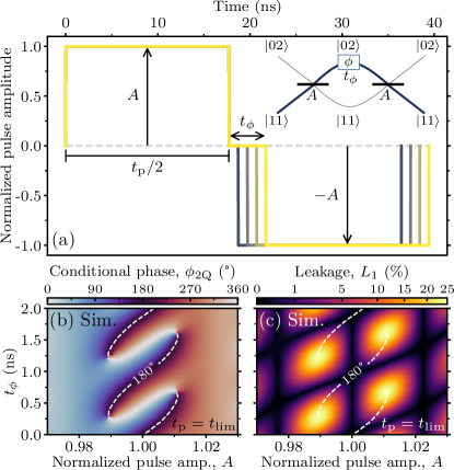
The key advantage of SNZ over conventional NZ is the very straightforward procedure to simultaneously meet PC and LC3. To appreciate this, consider first the ideal scenario where the pulses can have infinite time resolution. For, , (), and () each half pulse implements an iSWAP gate between and . Thus, (meeting LC3) and (meeting PC). In the MZI analogy, the first beamsplitter fully transmits to (producing maximal intermediate leakage), and the second fully transmits to .
Consider now the effect of non-zero . The idealized two-qutrit numerical simulation with infinite time resolution and no decoherence in Fig. 1 shows that the landscapes of and as a function of and have a clear structure and link to each other. Evidently, is -periodic in , so both landscapes are vertically periodic. The landscape shows a vertical leakage valley at , where LC3 is met. LC2 gives rise to additional, diagonally running valleys. Juxtaposing the contour of shows that PC is met at the crossing points between these valleys. In this way, this regular leakage landscape provides useful crosshairs for simultaneously meeting PC. We note that along the LC3 vertical valley, changes monotonically as a function of , allowing the realization of CP gates with any desired . We leave this useful generalization for future work, focusing here on CZ gates.
While in this idealized scenario the idling period is not needed, there are practical reasons to include in experiment: any flux-pulse distortion remaining from the first half pulse during the second (e.g., due to finite pulse rise time) will break the symmetry . Due to the time resolution of the AWG used for flux control, can only increment in steps of , where is the detuning at the bias point. As typically and , one may only use the number of intermediate sampling points for very coarse control. For fine control, we propose to use the amplitude of the first and last sampling points during SOM .
With these considerations, we turn to the experimental realization of SNZ CZ gates between the nearest-neighbor pairs among four transmons in a 7-transmon processor. High- and low-frequency transmons ( and , respectively) connect to two mid-frequency transmons ( and ) using bus resonators dedicated to each pair. Each transmon has a flux-control line for two-qubit gating, a microwave-drive line for single-qubit gating, and a dispersively coupled resonator with Purcell filter for readout Heinsoo et al. (2018); Bultink et al. (2020). All transmons can be measured simultaneously by frequency multiplexing using a common feedline. See SOM for device details and a summary of measured transmon parameters, single-qubit-gate and readout performance. Each transmon is biased at its sweetspot using static flux bias to counter residual offsets. Flux pulsing is performed using a Zurich Instruments HDAWG-8 . Following prior work Rol et al. (2019, 2020), we measure the linear-dynamical distortions in the flux-control lines using the Cryoscope technique and correct them using real-time filters built into the AWG.
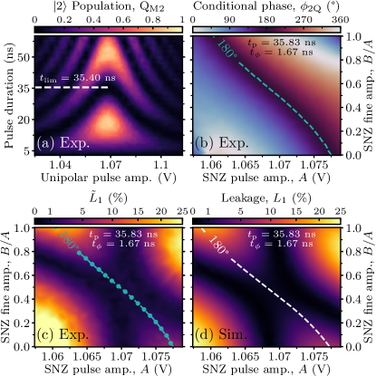
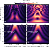
We exemplify the tuneup of SNZ pulses using pair - (Fig. 2). We first identify for the - interaction and the amplitude bringing the two levels on resonance. (The rightmost index indicates the excitation level of the fluxed transmon, here ). These parameters are extracted from the characteristic chevron pattern of -population in as a function of the amplitude and duration of a unipolar square flux pulse acting on [Fig. 2(a)]. The chevron symmetry axis corresponds to and the oscillation period along this axis gives . We set , where is the smallest integer satisfying . Next, we measure the landscapes of and leakage estimate in the range , . These quantities are extracted from the conditional-oscillation experiments described in Rol et al. (2019). As expected, the landscape of [Fig. 2(c)] reveals a vertical valley at and a diagonal valley. Juxtaposing the contour extracted from the landscape [Fig. 2(b)], we observe the matching of PC at the crossing of these valleys. These experimental observations are in excellent agreement with a numerical two-qutrit simulation [Fig. 2(d)].
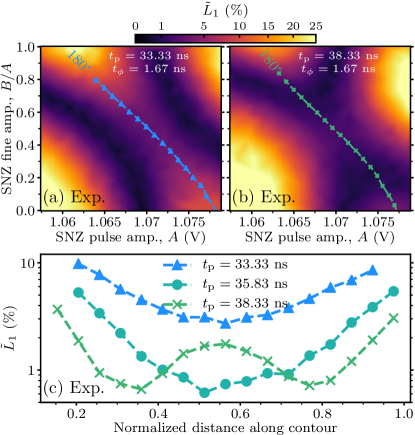
Experimentally, it is nearly impossible to precisely match due to the discrete . To understand the possible consequences of mismatch, we examine the and landscapes for SNZ pulses with intentionally set (Fig. 3). We find that the PC contour remains roughly unchanged in both cases. However, there are significant effects on . In both cases, we observe that lifts at the prior crossing of LC2 and LC3 valleys where . For too-short pulses [Fig. 3(a)], there remain two valleys of minimal , but these are now curved and do not cross the contour. For too-long pulses [Fig. 3(b)], there are also two curved valleys. Crucially, these cross the contour, and it remains possible to achieve PC and minimize leakage at two settings. Extracting along the contours [Fig. 3(c)] confirms that the minimal leakage obtainable for matches that for . The observed impossibility to achieve minimal leakage at for is a clear manifestation of the speed limit set by . In turn, the demonstrated possibility to do so for (even when overshooting by several sampling points) is an important proof of the viability of the SNZ pulse in practice.
With these insights, we proceed to tuning SNZ CZ gates for the four transmon pairs, following similar procedures. Namely, we use final weak bipolar pulses of total duration to null the single-qubit phases in the frame of microwave drives. Also, since our codeword-based control electronics has a timing grid, and for all pairs, we allocate to every CZ gate. However, some pair-specific details must be noted. Owing to the overlap of qubit frequencies between mid-frequency qubits, implementing CZ between and requires parking of during the SNZ pulse on Versluis et al. (2017); Andersen et al. . The parking flux pulse is also bipolar, with each half a square pulse lasting . Its amplitude is chosen to downshift the parked qubit by , and fine tuned to null its single-qubit phase. For most pairs, we employ the - interaction, which requires the smallest flux amplitude (reducing the impact of dephasing from flux noise) and does not require crossing any other interaction on the way to and from it. However, for pair -, we cannot reliably use this interaction as there is a flickering two-level system (TLS) aligned with the qubit transition at this amplitude (See SOM for chevron measurements showing the flickering nature of this TLS). For this pair, we therefore employ the - interaction. Using square pulses is a side benefit of SNZ in this case: it minimizes exchange between and the TLS, and , and and as their resonances are crossed as suddenly as possible.
| Parameter | - | - | - | - |
|---|---|---|---|---|
| 2.92 | 3.75 | 1.25 | 1.67 | |
| Interaction | - | - | - | - |
| Parked qubit | – | – | ||
| Avg. | ||||
| Avg. | ||||
| Max. | ||||
| Min. |
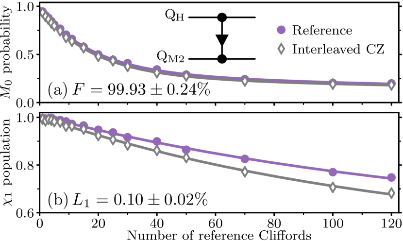
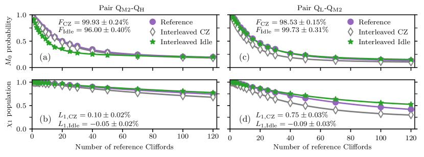
Table 1 summarizes the timing parameters and performance attained for the four SNZ CZ gates. The CZ gate fidelity and leakage are extracted using a 2QIRB protocol modified to quantify leakage Wood and Gambetta (2018); Rol et al. (2019). For each pair, we report the best, average and standard deviation of both values based on at least 10 repetitions of the protocol spanning more than SOM . Several observations can be drawn. First, CZ gates involving perform better on average than those involving . This is likely due to the shorter and correspondingly longer time spent near the sweetspot. Another possible reason is that the frequency downshifting required of to interact with and is roughly half that required of the latter to interact with . This reduces the impact of dephasing from flux noise during the pulse. Not surprisingly, performance is worst for the pair -. Here, the pulse must downshift the most in order to reach the distant - interaction, increasing dephasing from flux noise. Also, there may be residual exchange with the identified TLS and as the - and - resonances are crossed. Overall, there is significant variation in the performance metrics during repeated 2QIRB characterization. We believe this reflects the underlying variability of qubit relaxation and dephasing times, which however were not tracked simultaneously. In addition to having the best average performance, pair - also displays the hero performance based on a single 2QIRB run (Fig. 4). Peaking at , we believe this is the highest CZ fidelity extracted from 2QIRB characterization in a multi-transmon processor.
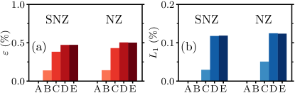
In an effort to identify the dominant sources of infidelity and leakage for SNZ CZ gates, we perform a two-qutrit numerical simulation for pair - with an error model taking parameters from experiment [Fig. 5]. As in our previous work on conventional NZ Rol et al. (2019), the simulation incrementally adds: (A) no noise; (B) energy relaxation; (C) Markovian dephasing; (D) dephasing from low-frequency flux noise; and (E) flux-pulse distortion. The experimental inputs for models B, C and D combine measured qubit relaxation time at the bias point, and measured echo and Ramsey dephasing times ( and ) as a function of qubit frequency. The input to E consists of a final Cryoscope measurement of the flux step response using all real-time filters. The simulation suggests that the main source of is Markovian dephasing (as in Rol et al. (2019)), while the dominant contribution to is low-frequency flux noise. The latter contrasts with Ref. Rol et al. (2019), where simulation identified flux-pulse distortion as the dominant leakage source. We identify two possible reasons for this difference: in the current experiment, the low-frequency flux noise is times larger (in units of ) and the achieved flux step response is noticeably sharper. Finally, we use the simulation to compare performance of SNZ to conventional NZ CZ. For the latter, we fix , , and use the fast-adiabatic pulse shape and optimized by simulation. Overall, the error sources contribute very similarly to the error budget for both cases. The marginally higher overall performance found for SNZ is likely due to the increased time spent at the sweetspot during the allocated for each CZ.
In summary, we have proposed and implemented the sudden variant of the NZ pulsing scheme Rol et al. (2019) realizing flux-based CZ gates by exploiting transverse coupling between computational and non-computation states. SNZ operates at the speed limit of transverse coupling by maximizing the intermediate leakage to the non-computational state. The key advantage of SNZ over conventional NZ is ease of tuneup, owing to the simple structure of error landscapes as a function of pulse parameters. We have demonstrated high-fidelity CZ gates between four transmon pairs in a patch of our 7-transmon processor. To the best of our knowledge, the best fidelity extracted from 2QIRB extends the state of the art. Control architectures without a timing grid will additionally benefit from the increased speed of SNZ over conventional NZ by reducing the total gate time and thus the impact of decoherence. Taking advantage of the tuning simplicity, we already employ SNZ CZ gates in the Starmon-5 quantum processor publicly available via the QuTech Quantum Inspire platform Qua . Moving forwards, the full compatibility of SNZ with our proposed Versluis et al. (2017) scalable scheme for surface coding makes SNZ our choice for CZ gates as we pursue quantum error correction. Finally, the noted straightforward extension of SNZ to arbitrary conditional-phase gates will find immediate application in NISQ applications.
Acknowledgements.
We thank L. Janssen, M. Rol, M. Sarsby, T. Stavenga, and B. Tarasinski for experimental assistance, C. Eichler and B. Terhal for discussions, and G. Calusine and W. Oliver for providing the travelling-wave parametric amplifier used in the readout amplification chain. This research is supported by the Office of the Director of National Intelligence (ODNI), Intelligence Advanced Research Projects Activity (IARPA), via the U.S. Army Research Office Grant No. W911NF-16-1-0071, and by Intel Corporation. The views and conclusions contained herein are those of the authors and should not be interpreted as necessarily representing the official policies or endorsements, either expressed or implied, of the ODNI, IARPA, or the U.S. Government. F. B. is supported by ERC Grant EQEC No. 682726.References
- Kjaergaard et al. (2019) M. Kjaergaard, M. E. Schwartz, J. Braumüller, P. Krantz, J. I. J. Wang, S. Gustavsson, and W. D. Oliver, ArXiv:1905.13641 (2019).
- Arute et al. (2019) F. Arute, K. Arya, R. Babbush, D. Bacon, J. C. Bardin, R. Barends, R. Biswas, S. Boixo, F. G. S. L. Brandao, D. A. Buell, B. Burkett, Y. Chen, Z. Chen, B. Chiaro, R. Collins, W. Courtney, A. Dunsworth, E. Farhi, B. Foxen, A. Fowler, C. Gidney, M. Giustina, R. Graff, K. Guerin, S. Habegger, M. P. Harrigan, M. J. Hartmann, A. Ho, M. Hoffmann, T. Huang, T. S. Humble, S. V. Isakov, E. Jeffrey, Z. Jiang, D. Kafri, K. Kechedzhi, J. Kelly, P. V. Klimov, S. Knysh, A. Korotkov, F. Kostritsa, D. Landhuis, M. Lindmark, E. Lucero, D. Lyakh, S. Mandrà, J. R. McClean, M. McEwen, A. Megrant, X. Mi, K. Michielsen, M. Mohseni, J. Mutus, O. Naaman, M. Neeley, C. Neill, M. Y. Niu, E. Ostby, A. Petukhov, J. C. Platt, C. Quintana, E. G. Rieffel, P. Roushan, N. C. Rubin, D. Sank, K. J. Satzinger, V. Smelyanskiy, K. J. Sung, M. D. Trevithick, A. Vainsencher, B. Villalonga, T. White, Z. J. Yao, P. Yeh, A. Zalcman, H. Neven, and J. M. Martinis, Nature 574, 505 (2019).
- Fowler et al. (2012) A. G. Fowler, M. Mariantoni, J. M. Martinis, and A. N. Cleland, Phys. Rev. A 86, 032324 (2012).
- Bultink et al. (2020) C. C. Bultink, T. E. O’Brien, R. Vollmer, N. Muthusubramanian, M. W. Beekman, M. A. Rol, X. Fu, B. Tarasinski, V. Ostroukh, B. Varbanov, A. Bruno, and L. DiCarlo, Science Advances 6, 10.1126/sciadv.aay3050 (2020).
- Andersen et al. (2019) C. K. Andersen, A. Remm, S. Lazar, S. Krinner, J. Heinsoo, J.-C. Besse, M. Gabureac, A. Wallraff, and C. Eichler, npj Quantum Information 5, 1 (2019).
- (6) C. K. Andersen, A. Remm, S. Lazar, S. Krinner, N. Lacroix, G. J. Norris, M. Gabureac, C. Eichler, and A. Wallraff, Nat. Phys. 16, 875.
- Strauch et al. (2003) F. W. Strauch, P. R. Johnson, A. J. Dragt, C. J. Lobb, J. R. Anderson, and F. C. Wellstood, Phys. Rev. Lett. 91, 167005 (2003).
- DiCarlo et al. (2009) L. DiCarlo, J. M. Chow, J. M. Gambetta, L. S. Bishop, B. R. Johnson, D. I. Schuster, J. Majer, A. Blais, L. Frunzio, S. M. Girvin, and R. J. Schoelkopf, Nature 460, 240 (2009).
- Sheldon et al. (2016) S. Sheldon, E. Magesan, J. M. Chow, and J. M. Gambetta, Physical Review A 93, 060302 (2016).
- Hong et al. (2020) S. S. Hong, A. T. Papageorge, P. Sivarajah, G. Crossman, N. Didier, A. M. Polloreno, E. A. Sete, S. W. Turkowski, M. P. da Silva, and B. R. Johnson, Phys. Rev. A 101, 012302 (2020).
- Barends et al. (2019) R. Barends, C. M. Quintana, A. G. Petukhov, Y. Chen, D. Kafri, K. Kechedzhi, R. Collins, O. Naaman, S. Boixo, F. Arute, K. Arya, D. Buell, B. Burkett, Z. Chen, B. Chiaro, A. Dunsworth, B. Foxen, A. Fowler, C. Gidney, M. Giustina, R. Graff, T. Huang, E. Jeffrey, J. Kelly, P. V. Klimov, F. Kostritsa, D. Landhuis, E. Lucero, M. McEwen, A. Megrant, X. Mi, J. Mutus, M. Neeley, C. Neill, E. Ostby, P. Roushan, D. Sank, K. J. Satzinger, A. Vainsencher, T. White, J. Yao, P. Yeh, A. Zalcman, H. Neven, V. N. Smelyanskiy, and J. M. Martinis, Phys. Rev. Lett. 123, 210501 (2019).
- Varbanov et al. (2020) B. Varbanov, F. Battistel, B. M. Tarasinski, V. P. Ostroukh, T. E. O’Brien, B. M. Terhal, and L. DiCarlo, arXiv:2002.07119 (in prepartion (2020)).
- Aliferis and Terhal (2007) P. Aliferis and B. M. Terhal, Quantum Info. Comput. 7, 139 (2007).
- Ghosh et al. (2013) J. Ghosh, A. G. Fowler, J. M. Martinis, and M. R. Geller, Phys. Rev. A 88, 062329 (2013).
- Fowler (2013) A. G. Fowler, Phys. Rev. A 88, 042308 (2013).
- Suchara et al. (2015) M. Suchara, A. W. Cross, and J. M. Gambetta, Quantum Info. Comput. 15, 997 (2015).
- Ghosh and Fowler (2015) J. Ghosh and A. G. Fowler, Phys. Rev. A 91, 020302 (2015).
- DiCarlo et al. (2010) L. DiCarlo, M. D. Reed, L. Sun, B. R. Johnson, J. M. Chow, J. M. Gambetta, L. Frunzio, S. M. Girvin, M. H. Devoret, and R. J. Schoelkopf, Nature 467, 574 (2010).
- Barends et al. (2014) R. Barends, J. Kelly, A. Megrant, A. Veitia, D. Sank, E. Jeffrey, T. C. White, J. Mutus, A. G. Fowler, B. Campbell, Y. Chen, Z. Chen, B. Chiaro, A. Dunsworth, C. Neill, P. O’Malley, P. Roushan, A. Vainsencher, J. Wenner, A. N. Korotkov, A. N. Cleland, and J. M. Martinis, Nature 508, 500 (2014).
- Kelly et al. (2015) J. Kelly, R. Barends, A. G. Fowler, A. Megrant, E. Jeffrey, T. White, D. Sank, J. Mutus, B. Campbell, Y. Chen, B. Chiaro, A. Dunsworth, I.-C. Hoi, C. Neill, P. J. J. O’Malley, C. Quintana, P. Roushan, A. Vainsencher, A. N. Cleland, J. Wenner, and J. M. Martinis, Nature 519, 66 (2015).
- Martinis and Geller (2014) J. M. Martinis and M. R. Geller, Phys. Rev. A 90, 022307 (2014).
- Krinner et al. (2020) S. Krinner, S. Lazar, A. Remm, C. Andersen, N. Lacroix, G. Norris, C. Hellings, M. Gabureac, C. Eichler, and A. Wallraff, arXiv preprint arXiv:2005.05914 (2020).
- Chen et al. (2014) Y. Chen, C. Neill, P. Roushan, N. Leung, M. Fang, R. Barends, J. Kelly, B. Campbell, Z. Chen, B. Chiaro, A. Dunsworth, E. Jeffrey, A. Megrant, J. Y. Mutus, P. J. J. O’Malley, C. M. Quintana, D. Sank, A. Vainsencher, J. Wenner, T. C. White, M. R. Geller, A. N. Cleland, and J. M. Martinis, Phys. Rev. Lett. 113, 220502 (2014).
- Yan et al. (2018) F. Yan, P. Krantz, Y. Sung, M. Kjaergaard, D. L. Campbell, T. P. Orlando, S. Gustavsson, and W. D. Oliver, Physical Review Applied 10, 054062 (2018).
- Mundada et al. (2019) P. Mundada, G. Zhang, T. Hazard, and A. Houck, Physical Review Applied 12, 054023 (2019).
- Collodo et al. (2020) M. C. Collodo, J. Herrmann, N. Lacroix, C. K. Andersen, A. Remm, S. Lazar, J.-C. Besse, T. Walter, A. Wallraff, and C. Eichler, arXiv preprint arXiv:2005.08863 (2020).
- Xu et al. (2020) Y. Xu, J. Chu, J. Yuan, J. Qiu, Y. Zhou, L. Zhang, X. Tan, Y. Yu, S. Liu, J. Li, F. Yan, and D. Yu, arXiv preprint arXiv:2006.11860 (2020).
- Schreier et al. (2008) J. A. Schreier, A. A. Houck, J. Koch, D. I. Schuster, B. R. Johnson, J. M. Chow, J. M. Gambetta, J. Majer, L. Frunzio, M. H. Devoret, S. M. Girvin, and R. J. Schoelkopf, Phys. Rev. B 77, 180502 (2008).
- Rol et al. (2019) M. A. Rol, F. Battistel, F. K. Malinowski, C. C. Bultink, B. M. Tarasinski, R. Vollmer, N. Haider, N. Muthusubramanian, A. Bruno, B. M. Terhal, and L. DiCarlo, Phys. Rev. Lett. 123, 120502 (2019).
- Kjaergaard et al. (2020) M. Kjaergaard, M. E. Schwartz, A. Greene, G. O. Samach, M. O. A. Bengtsson, C. M. McNally, J. Braumüller, D. K. Kim, P. Krantz, M. Marvian, A. Melville, B. M. Niedzielski, Y. Sung, R. Winik, J. Yoder, D. Rosenberg, S. L. K. Obenland, . T. P. Orlando, I. Marvian, S. Gustavsson, and W. D. Oliver, ArXiv:2001.08838 (2020).
- Magesan et al. (2012) E. Magesan, J. M. Gambetta, and J. Emerson, Phys. Rev. A 85, 042311 (2012).
- Wood and Gambetta (2018) C. J. Wood and J. M. Gambetta, Phys. Rev. A 97, 032306 (2018).
- Versluis et al. (2017) R. Versluis, S. Poletto, N. Khammassi, B. M. Tarasinski, N. Haider, D. J. Michalak, A. Bruno, K. Bertels, and L. DiCarlo, Phys. Rev. Appl. 8, 034021 (2017).
- Lacroix et al. (2020) N. Lacroix, C. Hellings, C. Kraglund Andersen, A. Di Paolo, A. Remm, S. Lazar, S. Krinner, G. J. Norris, M. G. Gabureac, A. B. Blais, C. Eichler, and A. Wallraff, arXiv preprint arXiv:2005.05275 (2020).
- Barends et al. (2015) R. Barends, L. Lamata, J. Kelly, L. García-Álvarez, A. Fowler, A. Megrant, E. Jeffrey, T. White, D. Sank, J. Mutus, B. Campbell, Y. Chen, Z. Chen, B. Chiaro, A. Dunsworth, I.-C. Hoi, C. Neill, P. O’Malley, C. Quintana, P. Roushan, A. Vainsencher, J. Wenner, E. Solano, and J. Martinis, Nat. Commun. 6, 7654 (2015).
- Preskill (2018) J. Preskill, Quantum 2, 79 (2018).
- (37) See supplemental material.
- Heinsoo et al. (2018) J. Heinsoo, C. K. Andersen, A. Remm, S. Krinner, T. Walter, Y. Salathé, S. Gasparinetti, J.-C. Besse, A. Potočnik, A. Wallraff, and C. Eichler, Phys. Rev. Appl. 10, 034040 (2018).
- Rol et al. (2020) M. A. Rol, L. Ciorciaro, F. K. Malinowski, B. M. Tarasinski, R. E. Sagastizabal, C. C. Bultink, Y. Salathe, N. Haandbaek, J. Sedivy, and L. DiCarlo, Applied Physics Letters 116, 054001 (2020).
- Nijholt et al. (2019) B. Nijholt, J. Weston, J. Hoofwijk, and A. Akhmerov, Adaptive: parallel active learning of mathematical functions (2019).
- (41) Qutech Quantum Inspire, https://www.quantum-inspire.com/.
Supplemental material for ’High-fidelity controlled-Z gate with maximal intermediate leakage operating at the speed limit in a superconducting quantum processor’
This supplement provides additional information in support of statements and claims made in the main text. Section I summarizes the main differences between conventional NZ pulses and SNZ pulses. Section II provides further details on the device used and measured transmon parameters. Section III presents the characterization of single-qubit gate performance. Section IV provides evidence for the two-level system affecting the realization of SNZ CZ gates in pair - using the - interaction. Section V presents a characterization of the residual coupling between qubits at the bias point. Section VI summarizes the technical details of the CZ characterization by repeated 2QIRB.
I Comparison of conventional NZ pulses and SNZ pulses
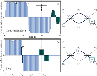
This section highlights the main differences between conventional NZ pulses and the SNZ pulses introduced here. The conventional NZ strong pulse [Fig. S1(a)] consists of two back-to-back half pulses of duration each, applied on the higher-frequency transmon. Typically, . The strong half pulses are formally parametrized as in Martinis and Geller (2014). For the purposes of illustration, here we can loosely lump this parametrization as affecting the amplitude () and curvature () of the strong half pulses. Immediately following the strong pulse, weak bipolar pulses of duration are applied on both the higher- and lower-frequency transmons with amplitudes and , respectively, in order to null the single-qubit phases acquired by each. Typically, . In conventional NZ there is no intermediate idling period between the strong half pulses, so the analogy to the MZI is not exact [Fig. S1(c)]. During tuneup, one searches the space to achieve by only affecting the unitary action of the two beamsplitters. Because for typical conventional NZ produces significant leakage at the first strong pulse, achieving minimal leakage relies on meeting LC2. The structure of the and landscapes and especially their interrelation are not straightforward, so the search for an setting satisfying both PC and LC2 is not easily guided. We point the interested reader to Rol et al. (2019) for examples.
The SNZ pulses introduced here [Fig. S1(b)] differ in two key ways. First, the strong half pulses are replaced by square half pulses each with duration as close as possible to (as allowed by the AWG sampling period) but not shorter. Second, an intermediate idling period is added to accrue relative phase between and , perfecting the analogy to the MZI [Fig. S1(d)]. We use the amplitude of the first and last sampling points in and the number of intermediate zero-amplitude points to achieve fine and coarse control of , respectively. As in conventional NZ, we use weak bipolar pulses on both transmons (also with ) to null the single-qubit phases. During tuneup, we search the space to achieve . As shown in the main text, the SNZ pulse design gives a very simple structure to the and landscapes. Crucially, the crossing point of leakage valleys satisfying LC2 and LC3 matches . This simplicity of tuneup is the key advantage of SNZ over conventional NZ.
Another advantage of SNZ over conventional CZ is the reduced total time required to achieve a CZ gate. However, due to the timing grid of our control electronics and the transverse coupling strengths in our device, this speedup is insufficient to reduce the total time allocated per CZ gate from to . Nonetheless, in SNZ, the fluxed transmon spends more time at its sweetspot, which reduces the dephasing due to flux noise.
II Device and transmon parameters
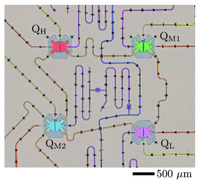
Our experimental study focuses on four transmons in a patch of our 7-qubit processor. An optical image of the device, zoomed in to these four transmons, is shown in Fig. S2. Transmons and both connect to and with a dedicated coupling bus resonator for each connection. Every transmon has a dedicated microwave-drive line for single-qubit gating, a flux-control line used for CZ gating, and a dispersively-coupled readout resonator with dedicated Purcell filter Heinsoo et al. (2018); Bultink et al. (2020) for readout. Readout is performed by frequency multiplexed measurement of a common feedline capacitively connected to all four Purcell filters. Table S1 provides a summary of measured parameters for the four transmons.
| Qubit transition frequency at sweetspot, | 6.4329 | 5.7707 | 5.8864 | 4.5338 |
| Transmon anharmonicity, | -280 | -290 | -285 | -320 |
| Readout frequency, | 7.4925 | 7.2248 | 7.0584 | 6.9132 |
| Relaxation time, | ||||
| Ramsey dephasing time, | ||||
| Echo dephasing time, | ||||
| Residual qubit excitation, | 1.4 | 1.2 | 4.3 | 1.7 |
| Best readout fidelity, (%) | 99.1 | 98.5 | 99.4 | 97.8 |
III Single-qubit gate performance
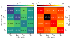
All single-qubit gates are implemented as DRAG-type Motzoi et al. (2009); Chow et al. (2010) microwave pulses with a total duration of , where is the Gaussian width of the main-quadrature Gaussian pulse envelope. We perform two sets of experiments to jointly quantify the infidelity and leakage of these gates. First, we perform individual single-qubit randomized benchmarking (1QRB) keeping the other three qubits in . Second, we perform simultaneous single-qubit randomized benchmarking (S1QRB) on pairs of qubits, keeping the other two qubits in . The results obtained from both types of experiment are reported as diagonal and off-diagonal elements in the matrices presented in Fig. S3.
IV Flickering two-level system
As mentioned in the main text, we were unable to realize the SNZ CZ gate between pair - using the - interaction due to the presence of a two-level system (TLS) interacting intermittently with at the flux amplitude placing and on resonance. Figures S4(a,b) show the negative impact of this TLS when attempting to characterize the - interaction by the standard time-domain chevron measurement. While experience shows that it is probable that such a TLS could be displaced or eliminated by thermal cycling at least above the critical temperature of aluminum, we chose instead to use the more flux distant - interaction to realize the SNZ CZ gate for this pair. For this interaction, a standard, stable chevron pattern is observed [Figs. S4(c,d)].
V Residual ZZ coupling at bias point
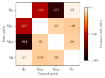
Coupling between nearest-neighbor transmons in our device is realized using dedicated coupling bus resonators. The non-tunability of said couplers leads to residual coupling between the transmons at the bias point. We quantify the residual coupling between every pair of qubits as the shift in frequency of one qubit when the state of the other changes from to . We extract this frequency shift using a simple time-domain measurement: we perform a standard echo experiment on one qubit (the echo qubit), but add a pulse on the other qubit (control qubit) halfway through the free-evolution period simultaneous with the refocusing pulse on the echo qubit. The results are presented as a matrix in Fig. S5. We observe that the residual coupling is highest between and the mid-frequency qubits and . This is consistent with the higher (lower) absolute detuning between () and the mid-frequency transmons, and the higher (lower) transverse coupling for the upper (lower) pairs.
An alternative way to evidence this residual coupling is to extract the fidelity of idling using 2QIRB and to compare this fidelity to that of CZ. To this end, we perform 2QIRB of idling (for ) on pairs - and -. The results, shown in Fig. S6, show striking differences for the two pairs. For -, the pair with strongest residual coupling, the idling fidelity is significantly lower than the CZ fidelity. This is because the residual coupling is a source of error during idling but is absorbed into the tuneup of SNZ. For -, for which the residual coupling is one order of magnitude lower, this trend is not observed.
VI Technical details on 2QIRB
Table S2 details technical aspects of the characterization of CZ gates by repeated 2QIRB runs.
| Parameter | - | - | - | - |
| Number of 2QIRB runs | ||||
| Number of randomization seeds | ||||
| Same randomization seeds | No | No | Yes | No |
| Avg. time per 2QIRB run () | ||||
| Total wall-clock time () |
References
- Martinis and Geller (2014) J. M. Martinis and M. R. Geller, Phys. Rev. A 90, 022307 (2014).
- Rol et al. (2019) M. A. Rol, F. Battistel, F. K. Malinowski, C. C. Bultink, B. M. Tarasinski, R. Vollmer, N. Haider, N. Muthusubramanian, A. Bruno, B. M. Terhal, and L. DiCarlo, Phys. Rev. Lett. 123, 120502 (2019).
- Heinsoo et al. (2018) J. Heinsoo, C. K. Andersen, A. Remm, S. Krinner, T. Walter, Y. Salathé, S. Gasparinetti, J.-C. Besse, A. Potočnik, A. Wallraff, and C. Eichler, Phys. Rev. Appl. 10, 034040 (2018).
- Bultink et al. (2020) C. C. Bultink, T. E. O’Brien, R. Vollmer, N. Muthusubramanian, M. W. Beekman, M. A. Rol, X. Fu, B. Tarasinski, V. Ostroukh, B. Varbanov, A. Bruno, and L. DiCarlo, Science Advances 6, 10.1126/sciadv.aay3050 (2020).
- Krantz et al. (2019) P. Krantz, M. Kjaergaard, F. Yan, T. P. Orlando, S. Gustavsson, and W. D. Oliver, Appl. Phys. Rev. 6, 021318 (2019).
- Bultink et al. (2018) C. C. Bultink, B. Tarasinski, N. Haandbaek, S. Poletto, N. Haider, D. J. Michalak, A. Bruno, and L. DiCarlo, Appl. Phys. Lett. 112, 092601 (2018).
- Motzoi et al. (2009) F. Motzoi, J. M. Gambetta, P. Rebentrost, and F. K. Wilhelm, Phys. Rev. Lett. 103, 110501 (2009).
- Chow et al. (2010) J. M. Chow, L. DiCarlo, J. M. Gambetta, F. Motzoi, L. Frunzio, S. M. Girvin, and R. J. Schoelkopf, Phys. Rev. A 82, 040305 (2010).
- Nijholt et al. (2019) B. Nijholt, J. Weston, J. Hoofwijk, and A. Akhmerov, Adaptive: parallel active learning of mathematical functions (2019).