Controllable supercurrent in mesoscopic superconductor-normal metal-ferromagnet crosslike Josephson structures
Abstract
A nonmonotonic dependence of the critical Josephson supercurrent on the injection current through a normal metal/ferromagnet weak link from a single domain ferromagnetic strip has been observed experimentally in nanofabricated planar crosslike S-N/F-S Josephson structures. This behavior is explained by 0- and -0 transitions, which can be caused by the suppression and Zeeman splitting of the induced superconductivity due to interaction between N and F layers, and the injection of spin-polarized current into the weak link. A model considering both effects has been developed. It shows the qualitative agreement between the experimental results and the theoretical model in terms of spectral supercurrent-carrying density of states of S-N/F-S structure and the spin-dependent double-step nonequilibrium quasiparticle distribution.
I Introduction
The interplay between spin-singlet superconductivity and ferromagnetism in mesoscopic hybrid structures leads to variety of novel effects actively investigated in the last decades. The most remarkable experiments were carried out using nonlocal technique of detection of the spin accumulation and injection in normal metals and superconductors johnson1994 ; Jedema1 ; Poli , coherent effects of crossed Andreev reflection and elastic cotunneling deutscher2000 ; BeckmannCAR ; Beckmann2 ; russo2005 ; Chandrasekhar , Zeeman splitting in superconductors with adjacent ferromagnetic insulators GiazottoEuS , charge and spin imbalance Hubler ; TG2014 ; wolf2013 ; FH2012 ; Quay , specific thermoelectric effects Kolenda2016 ; Kolenda2017 ; Kolenda2016_2 .
An unusual Josephson effect characterized by the inverse current-phase relation , the so called -state of a Josephson junction, was observed in quite macroscopic trilayered SFS systems with a weak ferromagnetic interlayer SFSVR ; Oboznov . There the temperature induced 0- transition was demonstrated. Experimentally feasible lateral superconductor (S)-normal metal (N)-ferromagnet (F) Josephson junctions manifesting the -state under certain conditions were studied in detail theoretically KarmPRB . Implementation of such structures as submicron-scale -phase shifters is of particular interest for superconducting and quantum electronics qbit , which has already been demonstrated with sandwich-type SFS Josephson junctions incorporated in superconducting logical schemes Feofanov and in the qubit loop Scherbakova . The future improvement is associated with the system size reduction by means of the fabrication of submicron lateral hybrid structures.
The driving out of equilibrium conditions makes it possible to achieve 0- transitions even without ferromagnets as it was predicted Wilhelm and demonstrated Baselmans1 for controllable SNS Josephson junctions. The transition into -state occurred there at a certain value of the control voltage across the N-barrier, which corresponds to a sign change in the spectrum of supercurrent-carrying states Im[]. The latter is characterized by the strongly damped oscillations with positive and negative parts which is cut out by the double-step-like electron distribution function or smeared by the thermal distribution function (see Fig.2 in Baselmans2 ).
It is predicted that for similar mesoscopic structures with ferromagnets crossSFS (or under an applied magnetic field Yip ) the spectral supercurrent is shifted due to the presence of the exchange or Zeeman field which leads to the redistribution of current-carrying states. The redistribution results in the suppression of the Josephson current in equilibrium. The recovery of the supercurrent by applying a suitable non-equilibrium distribution of quasiparticles was proposed. The recovery was predicted both for spin-independent Yip and for spin-dependent nonequilibrium quasiparticle distribution Bobkova2012 . The proper spin-dependent quasiparticle distribution is the most efficient way to recover the supercurrent. Moreover, transitions driven by the nonequilibrium quasiparticle distribution can be observed Yip ; Bobkova2010 ; Bobkov2011 .
In this article, we present the first observation of double 0- transition in crosslike S-N/F-S mesoscopic Al-Cu/Fe-Al structures. We claim that this effect is due to spectral supercurrent modification in the presence of the effective exchange field in the hybrid weak link and controllable non-equilibrium distribution of quasiparticles. The corresponding calculations for the geometry of our structures and the parameters obtained from the measurements show qualitative agreement with the experiment.
II Samples and experiment
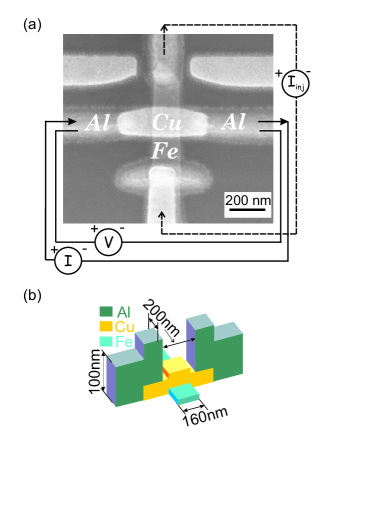
In the investigated structures Al, Cu and Fe were used as a superconductor (S), a normal metal (N), and a ferromagnet (F) correspondingly. Figure 1(a) shows a scanning electron microscopy (SEM) image of one of our samples, together with the measurement scheme, Fig. 1(b) demonstrates a schematic sketch of the structure with its geometrical dimensions. The submicron-scale crosslike S-N/F-S junctions were fabricated by means of electron beam lithography and in situ shadow evaporation. First, a thin (10-15 nm) iron layer was deposited onto an oxidized silicon substrate at the first angle to form a ferromagnetic injector. Then a copper layer of 60 nm (or 30 nm) thickness was evaporated at the second angle to create a complex N/F-weak link in the intersection area of N and F layers. Finally, a thick (100 nm) layer of aluminum was deposited at the third angle to form superconducting banks of the junction and electrical contacts to the perpendicular Fe electrode. All these technological steps were executed without breaking the vacuum, so that all FN and NS interfaces are assumed to be highly transparent. The geometrical dimensions are the same for all structures, i.e. the distance between superconducting banks is 200 nm, the width of iron strip is 160 nm, the width of copper strip is 200 nm (Fig. 1 (b)). Since the resistance of iron film with the specific resistance = 70 cm and thickness =10 nm is much larger than the resistance of thick copper film ( = 4.5 cm, =60 nm), the main part of current flows through the N layer.
The transport measurements were performed in a shielded cryostat at temperatures down to 0.3 K. Low-pass RC filters were incorporated into DC measurement lines directly on the sample holder in order to eliminate the external noise. The current-voltage characteristics of crosslike S-N/F-S junctions were measured by using the standard four-terminal configuration in presence of the injection current via the iron electrode as it is shown in Fig.1(a). The dimensions and thickness of the ferromagnetic strip have provided the single domain state with the practically uniform magnetization aligned parallel to the the strip, as it was demonstrated in our previous work TG2012 .
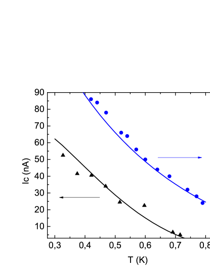
The Josephson supercurrent was observed only for samples with the thickness of copper layer =60 nm. In comparison with a reference S-N-S (Al-Cu-Al) Josephson junction with the same geometrical dimensions (the only difference was the absence of a perpendicular iron strip) the critical current of hybrid S-N/F-S structures was strongly suppressed. The temperature dependencies of the critical currents for both structures are shown in Fig. 2.
The suppression of the Josephson supercurrent in case of S-N/F-S structures is explained by the proximity of the ferromagnetic layer in contact with the copper layer in the weak link. Although the area of intersection of N and F layers in the cross-shaped S-N/F-S structures is much less than in the layer-on-layer weak link TG2012 , the F layer still affects considerably the transport superconducting coherence properties. The effective spin polarization is induced into the N layer due to relatively large spin diffusion length in Cu (=1 m at 1 K Kimura ) in comparison with the dimensions of Cu strip in the weak link (Fig.1). A mechanism of the supercurrent suppression in such systems has already been discussed in theoretical works crossSFS ; Yip and it is related to the modification of equilibrium spectral functions by their shifting with the effective exchange energy or Zeeman field in comparison with the normal metal case.
In the main experiments, the current-voltage (I-V) characteristics of the crosslike S-N/F-S junction were measured for different values of the injection current across the junction (Fig. 1(a)). From the I-V curves we determined the critical current for each value of the injection current as it is shown in Fig.3. One can see a clear nonmonotonic behavior of the critical current with the increasing of the injection current. This behavior does not depend on the injection current sign.
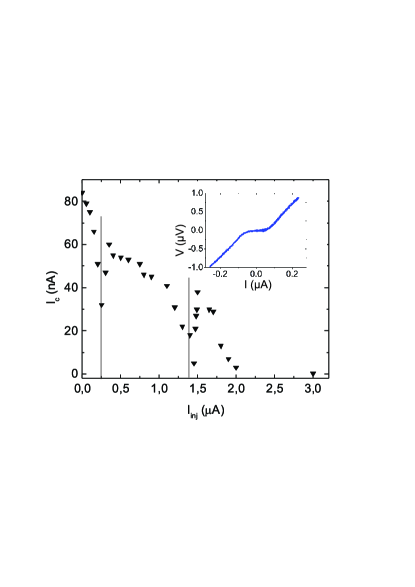
Generally, the dependence demonstrates the critical current decrease with the increasing of the injection current and two local dips at =0.25 A and =1.4 A. We suppose that the observed behavior is due to transitions between 0- and - states at node values and . As noted above, it was predicted that the different types of Josephson junctions with a complex N/F weak link can be in the -state even in equilibrium conditions KarmPRB , however, the -state is also possible in controllable SNS systems with noneqiulibrium electron distribution due to current injection Baselmans1 . In our work, we combine both approaches.
III Discussion
III.1 Quasiparticle distribution in the interlayer
We associate the mechanism of the -state formation with the redistribution in occupied fractions of positive and negative supercurrent-carrying density of states (SCDOS) Baselmans1 ; crossSFS ; Yip ; Bobkova2010 . For the case under consideration an effective exchange field is induced in the normal layer due to the proximity with the ferromagnet KarmPRB . It provides more complicated SCDOS in the interlayer than for the case of a conventional S/N/S Josephson junction (see detailed discussion below). In its turn this more rich structure of SCDOS makes the Josephson current more sensitive to the quasiparticle redistribution allowing for observation of the double-transition behavior.
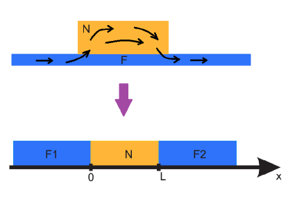
At first we describe the nonequilibrium quasiparticle distribution, which is formed in the normal part of the interlayer due to the current injection from the ferromagnet in our system depicted in Fig. 1. For simplicity, we suppose that no transverse current enters into the superconducting banks of the junction (since the low energy process taking place at energies much less than superconducting gap of aluminum =180 eV is considered, and, apart from this, the S parts are shifted away from the F one and have no intersection with it). We can consider our crosslike N/F system as F/N/F spin valve in parallel configuration (Fig. 4) since the main part of the injection current flows through the N layer, as it was noted above.
The quasiparticle distribution in the F layers can be described in terms of the different electrochemical potentials Jedema2 , while for the N layer such description is inappropriate because the N layer length is shorter than all the inelastic relaxation lengths and the Fermi distribution is not formed here. The spin relaxation length for Cu greatly exceeds the N layer length =200 nm, as it was noted above. Therefore, the spin relaxation term can also be neglected in the kinetic equation, which can be written for the distribution function for the spin subbands separately and takes the form:
| (1) |
This equation should be supplemented by the Kuprianov-Lukichev boundary conditions at :
| (2) |
where are electrochemical potentials for left (right) ferromagnets at the F/N interfaces, respectively and is the conductance of F/N interfaces for the spin subband . The solution of Eqs. (1)-(2) takes the form:
| (3) |
where and are taken at the corresponding N/F interfaces . The electrochemical potentials in the ferromagnets can be found from the appropriate diffusion equation and take the form Rashba2002 ; Jedema2 :
| (4) | |||
| (5) |
where is the spin diffusion length in the ferromagnets, is the ferromagnet conductivity for a given spin subband and for the up (down) subbands, respectively. Constants , and are to be found from the condition of the continuity of the electric current at the N/F interfaces for each of the spin subbands separately. The electric currents in the ferromagnets can be calculated as , while in the normal interlayer it should be calculated according to:
| (6) |
Then the condition at gives us constants , and , and the electrochemical potentials and entering Eq. (3) take the form:
| (7) | |||
| (8) |
with
| (9) |
Experimentally relevant parameters allow for disregarding the incline of the distribution function in the interlayer, described by the second term in Eq. (3). Then the distribution function can be considered as spatially constant and the characteristic example is plotted in Fig. 5 as a function of energy. It is seen that the distribution functions are different for the both spin subbands and exhibit the double-step structure, which is typical for mesoscopic regions between two leads, where the distribution function is not thermalized and is mainly determined by the distributions in the leads.
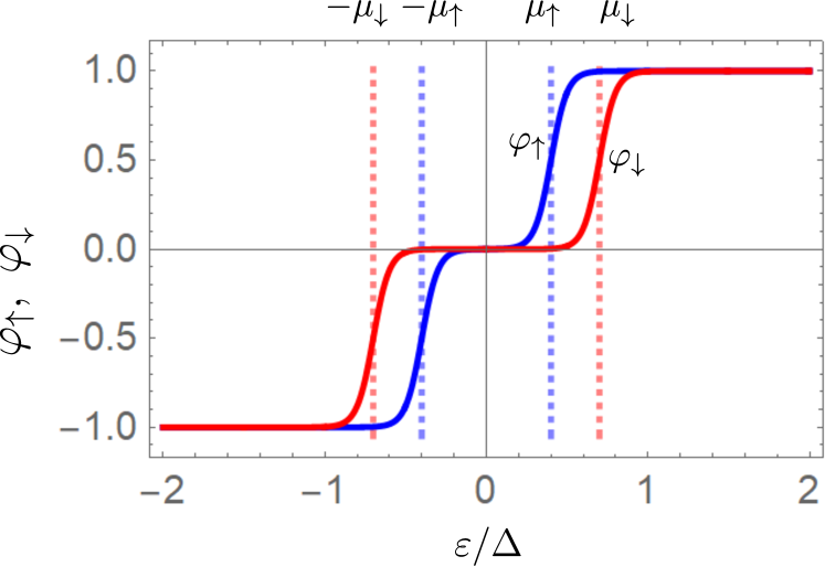
Because of the condition the distribution function is antisymmetric with respect to . Together with the fact that in general this leads to the conclusion that in the system under consideration two physically different modes of nonequilibrium quasiparticle distribution are nonzero. In notations of Refs. RMPBergeret, ; silaev2, they are and . The first one is the energy nonequilibrium mode. In general, it is associated with the nonequilibrium distribution of quasiparticles over energy levels. For example, excess energy can be pumped into the system due to the injection current. The resulting nonequilibrium distribution can be thermalized (the quasiparticle subsystem is overheated) or not thermalized. The latter case is realized in our experiment in the particular form of the double-step structure of the distribution function. is the so-called spin-energy mode, which can be associated with, roughly speaking, different energies pumped into spin-up and spin-down quasiparticles. If the spin-up and spin-down quasiparticle distributions are thermalized separately, it shows up as different effective temperatures for spin-up and spin-down quasiparticles. In our case of non-thermalized quasiparticle distributions it manifests itself by different widths of the double-step structure for spin-up and spin-down subsystems, see Fig. 5. The other two possible nonequilibrium modes (the charge imbalance and spin imbalance) are not excited in the system.
III.2 Critical current of the junction under qusiparticle injection
Below we describe the calculations of a supercurrent in the S-N/F-S contact. We consider S as an ordinary superconductor in equilibrium with the superconducting gap , complex N/F weak link as a normal metal with non-equilibrium distribution and Zeeman splitting and the depairing parameter . The latter parameter accounts for the leakage of the superconducting correlations into the ferromagnet and depairing there Rabinovich2019 . is the length of the N/F area (the distance between superconducting banks), is the specific conductance of the S-N/F boundaries, is the normal state resistance of the N/F area, is the conductivity and is the diffusion coefficient. The calculation is performed in the framework of Usadel equations for Green’s functions in the Keldysh technique. We linearize the Usadel equation in the interlayer region assuming that the S-N/F interfaces are low transparent. The assumption works quite well as it is indicated by further numerical estimates of the interface transparency. The critical current can be expressed via the SCDOS and the distribution function as follows:
| (10) |
where is the SCDOS for a given spin subband with
| (11) |
is the retarded Green’s function and .
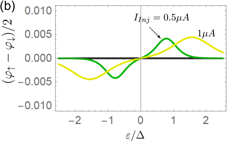
In general, . In our case, due to the antisymmetry of the distribution function this leads to , i.e. the effective quasiparticle distribution, which ”occupies” the SCDOS in Eq. (10), does not depend on spin. Therefore, only the energy nonequilibrium quasiparticle mode is relevant for the current situation.
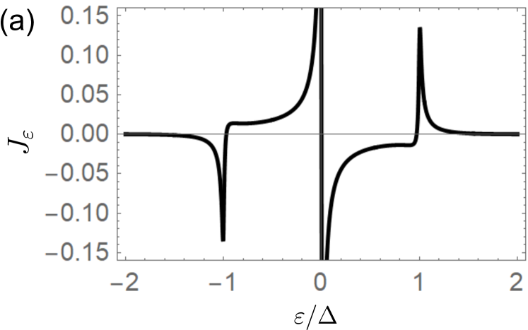
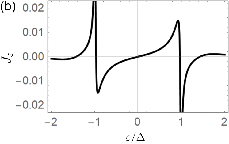
The SCDOS for our N/F interlayer is demonstrated in Fig. 6(b). The plot corresponds to the parameters , , and , where nm. These parameters are found by fitting the experimental data presented in Fig. 2. is an effective length of the normal interlayer, it does not exactly coincides with the actual length of the Cu region because the Cu regions underneath the Al leads and Cu regions between the Al leads and the Fe strip are partially proximitized by the Al superconductivity.
The SCDOS for the N/F interlayer should be compared to the SCDOS for a usual N interlayer corresponding to , [Fig. 6(a)]. It is seen that the SCDOS is a sign changing function. This is the reason providing the possibility for - transitions driven by an external parameter controlling the quasiparticle distribution. For the case of only one zero-crossing point at , as it takes place for the SCDOS in the N interlayer [Fig. 6(a)], no more than one - transition driven by injection, which results in the double-step or overheated quasiparticle distribution, is possible. This situation has been realized experimentally Baselmans1 . On the contrary, the SCDOS for our system manifests two zero-crossing points at due to the Zeeman splitting. This results in the possibility of two - transitions driven by injection.
The evolution of the distribution modes and upon increasing of the injection current is presented in Figs. 7(a,b), respectively. As it was discussed above for the problem under consideration, the critical current is only determined by . At zero temperature it manifests a four-step structure as a function of energy. The steps occur at . According to Eq. (5), the electrochemical potentials are proportional to the injection current . Therefore, , where taking the parameters of our F/N/F structure Soulen ; Stockmaier , , , =8.5 nm Fe we obtain and . It is seen that and are very close for the particular parameters of the structure. As a result, the spin-energy mode is rather small here, as it is demonstrated in Fig. 7(b) and the four-step structure is very close to the double-step one even at . Due to nonzero temperature this step structure is smeared. The temperature smearing is further increased because of the Joule heating by the injection current, which is modelled by with .
As it is seen from Fig. 7(a), upon increasing the injection current the quasiparticles are redistributed to higher energies leaving the low-energy states. This leads to gradual turning off the low-energy parts of the SCDOS. Therefore, the main part of the SCDOS contributing to the critical current changes sign upon increasing the injection current and the maximal number of --transitions is given by the number of zero-crossings in the SCDOS, as it was already mentioned above.
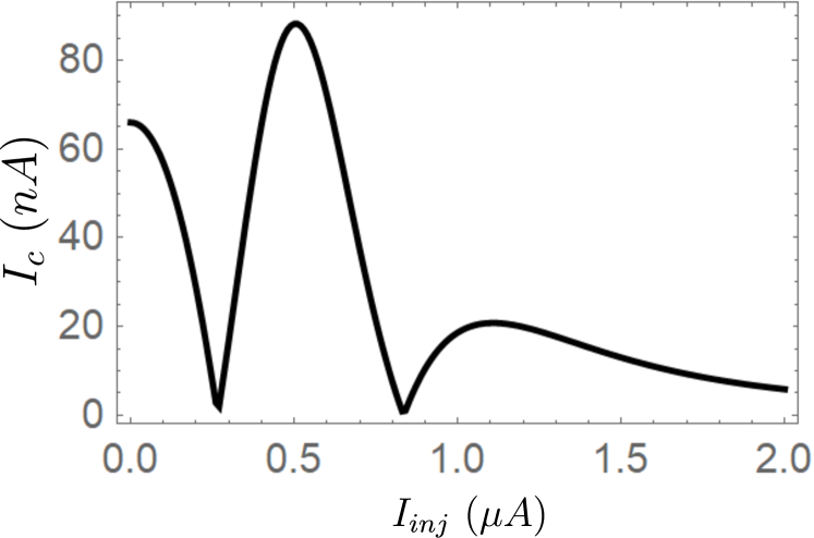
The critical current calculated in the framework of our theoretical model as a function of the injection current is presented in Fig. 8. It manifests two --transitions in qualitative agreement with the experimental results. However, the quantitative agreement is lacking because of the complicated geometry of the experimental structure. To obtain better approximation one should take into account that the real junction is not a simple S-N/F-S junction but contains regions of proximity superconductivity underneath the superconducting leads, which are very sensitive to the nonequilibrium quasiparticle distribution in the interlayer.
IV Conclusion
To conclude, we have demonstrated experimentally the double 0- transition in the crosslike S-N/F-S Josephson junctions driven in non-equilibrium by applying an injection current across the complex weak link. We ascribe this effect to the appearance of two zero-crossing points in the supercurrent-carrying density of states (SCDOS) caused by the Zeeman splitting of the superconducting correlations in the N/F interlayer. The model taking into account SCDOS of a S-N/F-S structure and spin injection into the N layer is developed to describe the observed effect. It has been concluded that the non-equilibrium in our case is not thermal, mainly described by the energy mode with a small amount of the spin-energy nonequilibrium mode without a contamination of charge and spin imbalance. Thus, we have shown that the Zeeman splitting due to N/F proximity has provided the origin of two nodes of the alternating SCDOS, which is practically impossible to realize in simple SNS structures without the F-sublayers used in the pioneering works Baselmans1 ; Baselmans2 . In our particular case, the spin-energy mode turned out to be negligible. To demonstrate the spin-energy mode manifestations, it is necessary that the distribution function has a spin splitting (i.e. the difference between and curves in Fig.5) significantly exceeding its temperature smearing. Our consideration can be applied for a general situation with the step-like distribution function by fabricating an appropriate structures and further temperature decrease, which, in particular, can be used for determination of the effective exchange field of the hybrid S-N-F structures with different transparency of interfaces.
The work was partially supported by grants of Russian Academy of Sciencies and Russian Foundation for Basic Research N 20-02-00864, 19-02-00452, 18-52-45011 and 18-02-00318, as well as by the Basic Research program of the Higher School of Economics.
References
- (1) M. Johnson, Spin coupled resistance observed in ferromagnet‐superconductor‐ferromagnet trilayers, Appl. Phys. Lett. 65, 1460 (1994).
- (2) F. J. Jedema, A. T. Filip, and B. J. van Wees, Electrical spin injection and accumulation at room temperature in an all-metal mesoscopic spin valve, Nature (London) 410, 345 (2001).
- (3) N. Poli, J. P. Morten, M. Urech, A. Brataas, D. B. Haviland and V. Korenivski, Spin Injection and Relaxation in a Mesoscopic Superconductor, Phys. Rev. Lett. 100, 136601 (2008).
- (4) G. Deutscher and D. Feinberg, Coupling superconducting-ferromagnetic point contacts by Andreev reflections, Appl. Phys. Lett. 76, 487 (2000).
- (5) D. Beckmann, H. B. Weber and H.v. Löhneysen, Evidence for Crossed Andreev Reflection in Superconductor-Ferromagnet Hybrid Structures, Phys. Rev. Lett. 93, 197003 (2004).
- (6) J. Brauer, F. Hübler, M. Smetanin, D. Beckmann, and H. v. Löhneysen, Nonlocal transport in normal-metal/superconductor hybrid structures: Role of interference and interaction, Phys. Rev B 81, 024515 (2010).
- (7) S. Russo, M. Kroug, T. M. Klapwijk and A. F. Morpurgo, Experimental Observation of Bias-Dependent Nonlocal Andreev Reflection, Phys. Rev. Lett. 95, 027002 (2005).
- (8) P. Cadden-Zimansky and V. Chandrasekhar, Nonlocal Correlations in Normal-Metal Superconducting Systems, Phys. Rev. Lett. 97, 237003 (2006).
- (9) E. Strambini, V. N. Golovach, G. De Simoni, J. S. Moodera, F. S. Bergeret, and F. Giazotto, Revealing the magnetic proximity effect in EuS/Al bilayers through superconducting tunneling spectroscopy, Phys. Rev. Materials. 1, 054402 (2017).
- (10) F. Hübler, J. Camirand Lemyre, D. Beckmann, and H. v. Löhneysen, Charge imbalance in superconductors in the low-temperature limit, Phys. Rev B 81, 184524 (2010).
- (11) T. E. Golikova, M. J. Wolf, D. Beckmann, I. E. Batov, I. V. Bobkova, A. M. Bobkov, and V. V. Ryazanov, Nonlocal supercurrent in mesoscopic multiterminal SNS Josephson junction in the low-temperature limit, Phys. Rev B 89, 104507 (2014).
- (12) M. J. Wolf, F. Hübler, S. Kolenda, H. v. Löhneysen, and D. Beckmann, Spin injection from a normal metal into a mesoscopic superconductor, Phys. Rev. B 87, 024517 (2013)
- (13) F. Hübler, M. J. Wolf, D. Beckmann,and H. v. Löhneysen, Long-Range Spin-Polarized Quasiparticle Transport in Mesoscopic Al Superconductors with a Zeeman Splitting, Phys. Rev. Lett. 109, 207001 (2012).
- (14) C. H. L. Quay, D. Chevallier, C. Bena, and M. Aprili, Spin imbalance and spin-charge separation in a mesoscopic superconductor, Nat. Phys. 9, 84-88 (2013)
- (15) S. Kolenda, M. J. Wolf, and D. Beckmann, Observation of Thermoelectric Currents in High-Field Superconductor-Ferromagnet Tunnel Junctions, Phys. Rev. Lett. 116, 097001 (2016).
- (16) S. Kolenda, C. Surgers, G. Fischer, and D. Beckmann, Thermoelectric effects in superconductor-ferromagnet tunnel junctions on europium sulfide, Phys. Rev. B 95 224505 (2017).
- (17) S. Kolenda, P. Machon, D. Beckmann, and W. Belzig, Nonlinear thermoelectric effects in high-field superconductor-ferromagnet tunnel junctions, Beilstein J. Nanotechnol. 7 1579 (2016).
- (18) V. V. Ryazanov, V. A. Oboznov, A. Yu. Rusanov, A. V. Veretennikov, A. A. Golubov, and J. Aarts, Coupling of Two Superconductors through a Ferromagnet: Evidence for a Junction, Phys. Rev. Lett. 86, 2427 (2001).
- (19) V. A. Oboznov, V. V. Bol’ginov, A. K. Feofanov, V. V. Ryazanov, and A. I. Buzdin, Thickness Dependence of the Josephson Ground States of Superconductor-Ferromagnet-Superconductor Junctions, Phys. Rev. Lett. 96, 197003 (2006).
- (20) T. Yu. Karminskaya, A. A. Golubov, M. Yu. Kupriyanov, and A. S. Sidorenko, Josephson effect in superconductor/ferromagnet structures with a complex weak-link region, Phys. Rev. B 81, 214518 (2010).
- (21) T. Yamashita, K. Tanikawa, S. Takahashi, and S. Maekawa, Superconducting Qubit with a Ferromagnetic Josephson Junction, Phys. Rev. Lett. 95, 097001 (2005).
- (22) A. K. Feofanov, V. A. Oboznov, V. V. Bol’ginov, J. Lisenfeld, S. Poletto, V. V. Ryazanov, A. N. Rossolenko, M. Khabipov, D. Balashov, A. B. Zorin, P. N. Dmitriev, V. P. Koshelets, and A. V. Ustinov, Implementation of superconductor/ferromagnet/ superconductor -shifters in superconducting digital and quantum circuits, Nature Phys. 6, 593–597 (2010)
- (23) A. V. Shcherbakova, K. G. Fedorov, K. V. Shulga, V. V. Ryazanov, V. V. Bolginov, V. A. Oboznov, S. V. Egorov, V. O. Shkolnikov, M. J. Wolf, D. Beckmann and A. V. Ustinov, Fabrication and measurements of hybrid Nb/Al Josephson junctions and flux qubits with -shifters, Supercond. Sci. Technol. 28, 025009 (2015)
- (24) F. K. Wilhelm, G. Schön, and A.D. Zaikin, Mesoscopic Superconducting–Normal Metal–Superconducting Transistor, Phys.Rev. Lett. 81, 1682 (1998).
- (25) J. J. A. Baselmans, A. F. Morpurgo, B. J. van Wees, and T. M. Klapwijk, Reversing the direction of the supercurrent in a controllable Josephson junction, Nature (London) 397, 43 (1999)
- (26) J. J. A. Baselmans, B. J. van Wees, and T. M. Klapwijk, Nonequilibrium supercurrent transport in controllable superconductor–normal-metal–superconductor junctions, Phys.Rev. B 63, 094504 (2001)
- (27) T. T. Heikkilä, F. K. Wilhelm and G. Schön, Non-equilibrium supercurrent through mesoscopic ferromagnetic weak links, EPL, 51, 434 (2000).
- (28) S.-K. Yip, Phys. Rev. B, Magnetic-field effect on the supercurrent of an SNS junction, 62, R6127 (2000).
- (29) I. V. Bobkova and A. M. Bobkov, Long-Range Proximity Effect for Opposite-Spin Pairs in Superconductor-Ferromagnet Heterostructures Under Nonequilibrium Quasiparticle Distribution, Phys. Rev. Lett. 108, 197002 (2012).
- (30) I. V. Bobkova and A. M. Bobkov, Triplet contribution to the Josephson current in the nonequilibrium superconductor/ferromagnet/superconductor junction, Phys. Rev. B 82, 024515 (2010).
- (31) A.M. Bobkov and I.V. Bobkova, Influence of spin-dependent quasiparticle distribution on the Josephson current through a ferromagnetic weak link, Phys. Rev. B 84, 054533 (2011).
- (32) T. E. Golikova, F. Hübler, D. Beckmann, I. E. Batov, T. Yu. Karminskaya, M. Yu. Kupriyanov, A. A. Golubov, and V. V. Ryazanov, Double proximity effect in hybrid planar superconductor-(normal metal/ferromagnet)-superconductor structures, Phys. Rev. B 86, 064416 (2012).
- (33) M. Hanson, O. Kazakova, P. Blomqvist, R. Wäppling, and B. Nilsson, Magnetic domain structures in submicron-size particles of epitaxial Fe (001) films: Shape anisotropy and thickness dependence, Phys. Rev. B 66, 144419 (2002).
- (34) T. Kimura, T. Sato, and Y. Otani, Temperature Evolution of Spin Relaxation in a NiFe/Cu Lateral Spin Valve, Phys. Rev. Lett. 100, 066602 (2008).
- (35) F. J. Jedema, M. S. Nijboer, A. T. Filip, and B. J. van Wees, Spin injection and spin accumulation in all-metal mesoscopic spin valves, Phys. Rev. B 67, 085319 (2003).
- (36) E.I. Rashba, Diffusion theory of spin injection through resistive contacts, Eur. Phys. J. B 29, 513 (2002).
- (37) F.S. Bergeret, M. Silaev, P. Virtanen, T.T. Heikkilä, Colloquium: Nonequilibrium effects in superconductors with a spin-splitting field, Rev. Mod. Phys. 90, 041001 (2018)
- (38) T. T. Heikkila, M. Silaev, P.Virtanen, and F. S. Bergeret, Thermal, electric and spin transport in superconductor/ferromagnetic-insulator structures, Progress in Surface Science, 94, 100540 (2019).
- (39) D. S. Rabinovich, I. V. Bobkova, A. M. Bobkov, and M. A. Silaev, Magnetoelectric effects in superconductor/ferromagnet bilayers, Phys. Rev. B 99, 214501 (2019).
- (40) R. J. Soulen Jr., J. M. Byers, M. S. Osofsky, B. Nadgorny, T. Ambrose, S. F. Cheng, P. R. Broussard, C. T. Tanaka, J. Nowak, J. S. Moodera, A. Barry, J. M. D. Coey, Measuring the Spin Polarization of a Metal with a Superconducting Point Contact, Science 282, 5386 85-88 (1998)
- (41) M. Stokmaier, G. Goll, D. Weissenberger, C. Sürgers, and H. v. Löhneysen, Size Dependence of Current Spin Polarization through Superconductor/Ferromagnet Nanocontacts, Phys. Rev. Lett. 101, 147005 (2008)
- (42) J. Bass, W. P. Pratt Jr., Spin-diffusion lengths in metals and alloys, and spin-flipping at metal/metal interfaces: an experimentalist’s critical review, J. Phys. Condens. Matter 19, 183207 (2007).