Erratum:
Fast and Simple Horizontal Coordinate Assignment
Abstract
We point out two flaws in the algorithm of Brandes and Köpf (Proc. GD 2001), which is often used for the horizontal coordinate assignment in Sugiyama’s framework for layered layouts. One of them has been noted and fixed multiple times, the other has not been documented before and requires a non-trivial adaptation. On the bright side, neither running time nor extensions of the algorithm are affected adversely.
Keywords:
Sugiyama layout Layered graph drawing Horizontal compaction.1 Introduction
Horizontal coordinate assignment is the final phase of Sugiyama’s framework for drawing directed graphs [sugiyama_etal:81, hn-hgda-13]. By that point, the original graph has been transformed into a directed acyclic graph with its vertices assigned to a sequence of layers, and ordered within these layers. Moreover, the layer assignment is proper, i.e., edges spanning layers are subdivided by dummy vertices so that two vertices are adjacent only if they are assigned to neighboring layers.
Brandes and Köpf [bk-fshca-02] proposed a simple algorithm to determine -coordinates for the vertices such that their order is preserved and the distance between each two vertices is at least some . The algorithm runs in time linear in the size of the input and is implemented and taught widely.
The original publication, however, contains two mistakes. The first is well known and easy to fix. The other, however, is not commonly known, less straightforward, and, to the best of our knowledge, no solution has been proposed.
The purpose of this short paper is to identify clearly where these two mistakes occur, and to provide suitable corrections. Our proposed corrections do not alter the behavior of the algorithm and do not clash with extensions that have been proposed to accommodate, for instance, vertices of varying size, ports, and other constraints [b-rasf-07, rsch-sphnca-15].
2 Background
In this section we sketch the algorithm of Brandes and Köpf. Two mistakes, both occurring in the same subroutine, are identified and corrected in the next section.
In the horizontal coordinate assignment problem, we are given a layered directed acyclic graph , i.e., a directed acyclic graph with two types of vertices (original vertices and potential bend points of edges) and a sequence of layers that forms an ordered partition of . The layering is required to be proper, i.e., adjacent vertices are in neighboring layers. Moreover, the vertices are ordered within each layer , where denotes the th vertex in the th layer. Thus, the topology of the drawing has already been fixed, and the horizontal coordinate assignment algorithm is now to determine the shape and the final metrics.
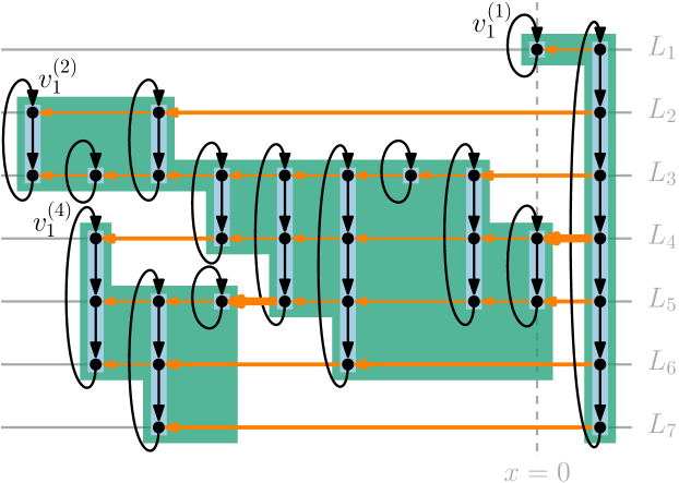
The algorithm of Brandes and Köpf consists of the following three steps, the first two of which are repeated four times, once for each combination of vertical and horizontal orientations. We describe the top-to-bottom, left-to-right case in which vertices are left-aligned conditional on upper neighbors; the other three cases are symmetric. Figure 1 illustrates the subsequent definitions.
-
1.
Vertical alignment: Every vertex is assigned a vertex,