Differential Reflecting Modulation for Reconfigurable Intelligent Surface Based Communications
Abstract
Reconfigurable intelligent surface (RIS) based communications have emerged as a new paradigm. This letter proposes a differential reflecting modulation (DRM) scheme for RIS based communication systems. In DRM, information bits are jointly carried by the activation permutations of the reflecting patterns and the phases of the transmitted signals, leading to that DRM can work without any channel state information (CSI) at the transmitter, RIS or receiver. In other words, DRM can release the intricate and resource-consuming channel estimation in the transmission process. Simulation results show that the proposed DRM pays an acceptable SNR penalty compared to non-differential modulation with coherent detection.
Index Terms:
Reconfigurable intelligent surface, differential reflecting modulation (DRM), differential detectionI Introduction
Reconfigurable intelligent surface (RIS) is a key enabler for configuring favorable wireless communication environment [1, 2]. The research on RIS based communication systems has attracted a lot of interest. In most of RIS based communication systems, information is modulated onto the phases/magnitudes of the transmitted signals[3, 4], where RIS only plays the role of an assister helping improve the communication performance. Recently, there is a large body of literature designing RIS as an information modulator, e.g., [5, 6, 7, 8, 9]. To be more specific, Tang et al designed a RIS enabled phase modulation scheme in [5] and radio frequency (RF) chain-free transmitters based on RIS in [6] and [7]. Basar et al in [8] proposed a RIS-enabled spatial modulation scheme, where information is not only modulated onto the phases/magnitudes of the transmitted signals but also onto the reflecting patterns. Yan et al proposed a passive beamforming and information transfer (PBIT), where RIS acts as a passive beamformer and also as an independent information modulator. [9] has made a comprehensive comparison among these RIS-enabled information transfers and proposed an optimized reflecting modulation (RM) scheme that outperforms all others.
So far, however, all existing schemes need to access the instantaneous/statistic channel state information (CSI) for detection. In RIS-based communication systems, the channel estimations involving transmitter-RIS, RIS-receiver, and the direct transmitter-receiver links are intricate tasks. This is because RIS units has no baseband signal precessing capabilities. Although some works on solving the critical channel estimation problem have been done, e.g., [10, 11], the channel estimation itself still consumes a lot of time and resources. In this letter, we propose a differential reflecting modulation (DRM) scheme. In DRM, information bits are encoded onto the activation permutation order of the reflecting patterns and also the phases of the transmitted signals. Such designs enables differential detection bypassing the resource-consuming channel estimation. The detection complexity and transmission rate are analyzed. Simulations results show that the proposed DRM scheme pays acceptable performance loss compared to non-differential reflecting modulation (NDRM) with perfect CSI. Besides that, we show that DRM can achieve comparable or even better performance than NDRM with channel estimation errors.
II System Model
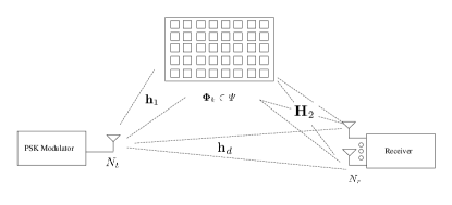
In this letter, a RIS-assisted single-input multiple-output (SIMO) communication system model as illustrated in Fig. 1, where the transmitter is equipped with one antenna; denotes the numbers of receiver antennas; stands for the number of reflecting units on the surface; and stands for the total transmission rate. In the system, the transmitter sends -ary phase shift-keying (PSK) symbols.
Let , , denote the transmitter-RIS channel vector, the RIS-receiver channel matrix, and the direct link channel vector. We assume that the channels are quasi-static Rayleigh fading channels. It is worth noting that Rayleigh fading channels are chosen as an example to demonstrate the performance and the proposed DRM scheme are also applicable to other channel models. Moreover, we assume that a total of reflecting pattern candidates are employed for transmission, which are included in a set . Each reflecting patten can be mathematically expressed as a diagonal matrix as . The diagonal elements of can be expressed as , where indicates the ON/OFF states of the th reflecting unit and represents the phase shift angle at the -th reflecting unit when the th reflecting pattern is activated.
III Differential Reflecting Modulation
III-A Differential Encoding Scheme
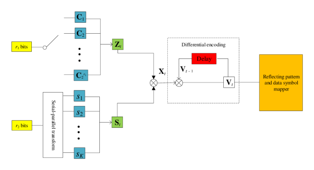
During the transmission, a frame is divided into blocks with each consisting of symbol time slots. The rationale behind this dividing is that reflecting pattern candidates will be activated in a permutation order during a block, which will occupy symbol time slots. At the th block, a total of bits are delivered. As shown in Fig. 2, the first bits are mapped to a permutation matrix . As is well known, there are legitimate permutation matrices. Here, we denote them as , receptively. In the mapping process, only matrices are chosen for the mapping process. To demonstrate the mapping process, an example with and is listed in Table I. In the demonstrated example, permutation matrices are chosen from legitimate candidates for carrying bits. It should be mentioned that different choices will result different performance. The rest bits are mapped to -PSK symbols . By stacking all symbols in a vector and defining , we introduce an information-carrying matrix given by
| (1) |
Based on such an encoding mechanism, the transmitter and RIS can either jointly or separately delivery information. If the transmitter and RIS are connected by backhaul links and share the same information source, they can jointly transmit information of bits. Besides that, the transmitter and RIS can also separately delivery information. In this case, the transmitter and RIS does not need to know the information of each other. At each block, RIS sends bits of its own and the transmitter sends bits of its own. It is noteworthy that the RIS and the transmitter have to be synchronized in a wired or wireless way for both cases. The synchronization is beyond this scope of this letter and we assume that the transmitter and RIS are well synchronized.
Based on , a new matrix can be generated after the differential encoding as
| (2) |
where is the matrix generated in the former block and is an identity matrix for initialization. Based on the definition of , it is easily verified that is a multiplication of a permutation matrix and a diagonal matrix as
| (3) |
where denotes a permutation matrix and represents a diagonal matrix whose symbols are chosen from the -PSK symbol set . This is because . As shown in Fig. 2, next step is to activate the reflecting pattens and modulate the phases of transmit signals according to during the th block, which will be given in the following subsection.
| Bits () | A permutation matrix () |
|---|---|
| 00 | |
| 01 | |
| 10 | |
| 11 |
III-B Signal Transmission
Let being -th column vector of and according to the form of in (3), can be expressed as
| (4) |
where represents the th basis vector with th elements being nonzero; and is the nonzero element of at the th position, which is an -PSK symbol. Then, according to , RIS activates the th reflecting pattern and the transmitter sends the -PSK symbol at the -th slot of the -th block. Thus, the received signal in the -th slot of the -th block can be written as111 In this letter, we consider the transmission is over quasi-static channels and assume that the time spread of multi-paths is not larger than a symbol time duration.
| (5) |
where represents the complex Gaussian noise vector with zero mean and .
By introducing the following matrices
| (6) |
| (7) |
| (8) |
| (9) |
we rewrite the expression of as
| (10) |
By setting , the transmission can be expressed as
| (11) |
where can be regarded as the equivalent channel matrix and can be regarded as the equivalent transmit vector. Thus, during the th block, the received signal matrix can be expressed by
| (12) |
where represents the received signal matrix, and is the complex Gaussian noise matrix.
III-C Detection Method
III-D Transmission Rate and Complexity Analysis
Considering the block for sending does not contain information, the effective transmission rate of DRM can be written as
| (15) |
in bits per channel use (bpcu), where denotes the number of blocks in total. Based on the Stirling formula, i.e., [12], the transmission rate is rewritten as
| (16) |
when is sufficiently large. It can be checked that the transmission rate increases as increases, but the increase rate is not fast. The detection computational complexity can be analyzed to be , since it needs to compute by times and each computation requires multiplications. Recall that , the computational complexity can be expressed as . Based on the expression of , it is found that the detection complexity increases much greatly as increases.
III-E Reflecting Pattern Selection
Above analysis indicates a good choice is to choose a small number of reflecting patterns for DRM, which can enjoy low-complexity detection. Then, how to perform reflecting pattern selection in a finite set for transmission arouses our interest. Since CSI is neither known by the transceivers nor by the RIS, we propose an optimization criterion to maximize the minimum mutual Euclidean distances, which is defined as . In this letter, we adopt the stepwise depletion algorithm proposed in [9]. The detailed procedure of the stepwise depletion algorithm can be found in [9] and we omit it for brevity.
III-F Impact of Channel Variation on DRM
When the channel varies, the proposed DRM will inevitably lead to detection errors like other differential modulation schemes. After the variation, i.e., when the channel becomes static again, the proposed DRM will work well again. To alleviate the impact, the transceiver can adopt bit interlevers/deinterleavers and error correcting codecs to correct the detection errors. Specifically, the bit interlevers/deinterleavers can spread the bit errors during the channel variation to multiple blocks resulting into a few of error bits per block, which can be corrected by error correction codecs.
IV Simulations
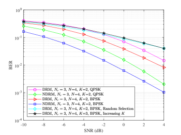
To show the performance of the proposed DRM scheme in RIS-based SIMO communication systems, we compare DRM with NDRM. In NDRM, is an transmission matrix and the received signal matrix . Perfect CSI (i.e., perfect , and ) is adopted for coherent detection. The rationale behind choosing the comparison is that the transmission rate and detection complexity of both schemes are the same. In the comparison, we assume RIS is with units with each unit being -bit encoded. That is, . Based on the assumption, we have legitimate reflecting patterns for DRM and NDRM transmission. We chose two (i.e., ) of them using the stepwise depletion algorithm [9]. The simulation results are depicted in Fig. 3. As the figure shows, DRM is less comparable to NDRM by dB under the given simulation setups. And in the simulations, the SNR is . For more comparison, we include the BER of DRM with an increasing (from to ). Simulation results show that the error performance of DRM decreases as increases. In addition, we also demonstrate the superiority of the proposed reflecting pattern selection over a random selection in Fig. 3.
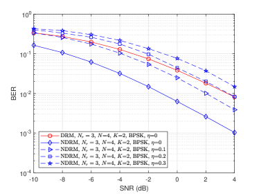
It is worth noting that DRM can work without CSI while NDRM have to spend much resource on channel estimation. Due to the fact that perfect CSI is typically not available, we further compare DRM and NDRM with imperfect CSI, where the imperfect CSI can be expressed by , and . In the error model, , and represent the error terms, with each elements in the matrix or vectors following a complex Gaussian distribution with zero mean and covariance [9], where is the positive proportional coefficient that is related to the number of pilots, the power and the employed algorithms for channel estimation. Simulation results are illustrated in Fig. 4, which demonstrate that the performance of NDRM reduces much as CSI errors increase. The difference between the performance of DRM and that of NDRM becomes small when . When and , DRM can outperform NDRM with coherent detection in the depicted SNR regime.
V Conclusion
In this letter, a differential modulation scheme named as DRM was proposed for RIS-based communication systems. In DRM, the information bits are jointly encoded onto the permutation order of the reflecting patterns and the phases of the transmit signals, which can be detected without knowing the channel state information. Simulation results showed that the difference between the proposed DRM and NDRM with coherent detection is acceptable, especially when there are inevitable channel estimation errors.
References
- [1] M. Di Renzo, M. Debbah, D.-T. Phan-Huy, A. Zappone, M.-S. Alouini, C. Yuen, V. Sciancalepore, G. C. Alexandropoulos, J. Hoydis, H. Gacanin et al., “Smart radio environments empowered by reconfigurable ai meta-surfaces: an idea whose time has come,” EURASIP Journal on Wireless Communications and Networking, vol. 2019, no. 1, pp. 1–20, May 2019.
- [2] S. Dang, O. Amin, B. Shihada, and M.-S. Alouini, “What should 6G be?” Nature Electronics, vol. 3, no. 1, pp. 20–29, Jan. 2020.
- [3] J. Ye, S. Guo, and M. Alouini, “Joint reflecting and precoding designs for SER minimization in reconfigurable intelligent surfaces assisted MIMO systems,” IEEE Trans. Wireless Commun., early access, 2020.
- [4] J. Qiao and M. Alouini, “Secure transmission for intelligent reflecting surface-assisted mmwave and terahertz systems,” IEEE Wireless Communications Letters, early access, 2020.
- [5] W. Tang, X. Li, J. Y. Dai, S. Jin, Y. Zeng, Q. Cheng, and T. J. Cui, “Wireless communications with programmable metasurface: Transceiver design and experimental results,” China Communications, vol. 16, no. 5, pp. 46–61, May 2019.
- [6] W. Tang, M. Z. Chen, J. Y. Dai, Y. Zeng, X. Zhao, S. Jin, Q. Cheng, and T. J. Cui, “Wireless communications with programmable metasurface: New paradigms, opportunities, and challenges on transceiver design,” IEEE Wireless Commun. Mag., vol. 27, no. 2, pp. 180–187, Apr. 2020.
- [7] W. Tang, J. Y. Dai, M. Chen, X. Li, Q. Cheng, S. Jin, K.-K. Wong, and T. J. Cui, “Programmable metasurface-based RF chain-free 8PSK wireless transmitter,” Electronics Letters, vol. 55, no. 7, pp. 417–420, Apr. 2019.
- [8] E. Basar, “Transmission through large intelligent surfaces: A new frontier in wireless communications,” in 2019 European Conference on Networks and Communications (EuCNC). IEEE, 2019, pp. 112–117.
- [9] S. Guo, S. Lv, H. Zhang, J. Ye, and P. Zhang, “Reflecting modulation,” IEEE J. Sel. Areas Commun., early access, 2020.
- [10] Q. Nadeem, A. Kammoun, A. Chaaban, M. Debbah, and M. Alouini, “Asymptotic max-min SINR analysis of reconfigurable intelligent surface assisted MISO systems,” IEEE Trans. Wireless Commun., early access, 2020.
- [11] Q. Nadeem, H. Alwazani, A. Kammoun, A. Chaaban, M. Debbah, and M. Alouini, “Intelligent reflecting surface-assisted multi-user MISO communication: Channel estimation and beamforming design,” IEEE Open Journal of the Communications Society, vol. 1, pp. 661–680, May 2020.
- [12] S. Guo, H. Zhang, P. Zhang, and D. Yuan, “Link-adaptive mapper designs for space-shift-keying-modulated MIMO systems,” IEEE Trans. Veh. Technol., vol. 65, no. 10, pp. 8087–8100, Oct. 2016.