A plate theory for nematic liquid crystalline solids
Abstract
We derive a Föppl-von Kármán-type constitutive model for solid liquid crystalline plates where the nematic director may or may not rotate freely relative to the elastic network. To obtain the reduced two-dimensional model, we rely on the deformation decomposition of a nematic solid into an elastic deformation and a natural shape change. The full solution to the resulting equilibrium equations consists of both the deformation displacement and stress fields. The model equations are applicable to a wide range of thin nematic bodies subject to optothermal stimuli and mechanical loads. For illustration, we consider certain reversible natural shape changes in simple systems which are stress free, and their counterparts, where the natural deformations are blocked and internal stresses appear. More general problems can be addressed within the same framework.
Keywords: liquid crystals, nematic solids, elastic plates, nonlinear deformation, multiplicative decomposition, stress.
1 Introduction
Liquid crystalline (LC) solids are complex materials that combine the elasticity of polymeric solids with the self-organisation of liquid crystal structures [20, 33]. Due to their molecular architecture, consisting of cross-linked networks of polymeric chains containing liquid crystal mesogens, their deformations are typically large and nonlinear, and can arise spontaneously and reversibly under certain external stimuli (heat, light, solvents, electric or magnetic field) [5, 13, 18, 19, 34, 44, 51, 52, 80, 87, 88, 94, 95, 104, 107, 109, 111]. These qualities suggest many avenues for technological applications, but more research efforts are needed before they can be exploited on an industrial scale [14, 27, 37, 39, 42, 63, 72, 78, 81, 85, 89, 92, 93, 106].
For thin nematic bodies, large deformations have been studied extensively, both theoretically and in laboratory. Rectangular geometries were assumed in [6, 17], circular discs were considered in [7, 8, 47, 48, 59, 60, 61, 64, 65, 69, 100], thin ribbons were treated theoretically in [1, 2, 3, 79] and experimentally in [73, 74, 86]. Different molecular structures and compositions, and the complex morphing behaviour that can be achieved in liquid crystal polymer networks were reviewed in [21, 50, 62, 68, 96, 105].
At the constitutive level, for ideal monodomain nematic solids, where the mesogens are aligned throughout the material, a general formulation is usually provided by the phenomenological neoclassical strain-energy function proposed in [12, 98, 103]. This model is based on the molecular network theory of rubber elasticity[83], where the parameters are directly measurable experimentally or derived from macroscopic shape changes [101, 102]. For nematic polydomains, where the mesogens are separated into many domains, such that in every domain, they that are aligned along a local director, in [10, 11], it is assumed that each domain has the same strain-energy density as a monodomain. Extensions to strain-energy functions for nematic elastomer plates with out-of-plane heterogeneities were proposed in [1, 2, 3]. General continuum mechanical theories for nematic elastomers are provided in [9, 110].
In this study, we derive a reduced two-dimensional (2D) model describing the equilibrium of thin nematic solids made of a liquid crystalline material subject to optothermal stimuli and mechanical loads. We first define the strain-energy function for a solid nematic material where the director may or may not rotate freely relative to the elastic matrix (Section 2), then formulate the corresponding stress tensors similar to those from the finite elasticity theory (Section 3). Here, we take as reference configuration the isotropic phase at high temperature [17, 24, 25, 26, 28] (inspired by the classical work of Flory (1961) [35] on polymer elasticity), rather than the nematic phase in which the cross-linking was produced [9, 12, 90, 97, 98, 103, 110]. The relation between the trace formula of [12] (using as reference orientation the one corresponding to the cross-linking state) and the neo-Hookean-based strain-energy density defined in [24] (with a “virtual” isotropic state as reference configuration) is explained in [28]. Similar nematic strain-energy densities based on other classical hyperelastic models (e.g., Money-Rivlin, Ogden) are also discussed in [28]. In adopting the isotropic phase as reference configuration, we follow Cirak et al. (2014) [17], where strain-energy functions with either free or frozen nematic director are defined, and the director has an initial direction which may be spatially varying. Our choice is phenomenologically motivated by the multiplicative decomposition of the deformation gradient from the reference configuration to the current configuration into an elastic distortion followed by a natural (stress free) shape change. This multiplicative decomposition is similar to those found in the constitutive theories of thermoelasticity, elastoplasticity, and growth [40, 55], but it is fundamentally different as the stress free geometrical change of liquid crystalline solids is superposed on the elastic deformation, which is applied directly to the reference state. Such difference is important since, although the elastic configuration obtained by this deformation may not be observed in practice, it may still be possible for the nematic body to assume such a configuration under suitable external stimuli. The elastic stresses can then be used to analyse the final deformation where the particular geometry also plays a role. However, in liquid crystalline materials, asymmetric Cauchy stresses generally occur, unlike in purely elastic materials [102, p. 80]. We employ the method of asymptotic expansions, with the thickness of the body as the small parameter, and show that the leading term of the expansion is the solution of a system of equations of the Föppl-von Kármán-type [36, 91] (Section 5). A similar model for the elastic growth of thin biological plates was developed in [23] (see also [22]). For an initial application of the plate theory, we consider ‘spontaneous’ nonlinear deformations of annular circular discs (Section 6). We conclude with a summary of these results and further remarks (Section 7).
2 An ideal nematic solid
For an ideal nematic liquid crystalline (NLC) solid, the neoclassical strain-energy density function takes the generic form
| (1) |
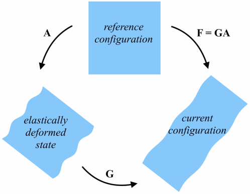
where F represents the deformation gradient from the isotropic state, n denotes the unit vector (or ‘director’) for the orientation of the nematic field, and is the strain-energy density of the isotropic polymer network, depending only on the (local) elastic deformation tensor A. The tensors F and A satisfy the relation (see Figure 1)
| (2) |
where G is the ‘natural’ (or ‘spontaneous’) deformation tensor defining a change of frame of reference from the isotropic phase to a nematic phase, and is equal to
| (3) |
In (3), is a temperature-dependent stretch parameter, denotes the optothermal analogue to the Poisson ratio [61], relating responses in directions parallel or perpendicular to the director n, stands for the tensor product of two vectors, and is the identity tensor. For example, spontaneous extensions or contractions of magnitude 10%-400% along n can occur in LC solids, while elastomers have , i.e., their volume remains unchanged during deformation, and glasses have [89, 96]. We assume here that and are spatially-independent (no differential swelling). These parameters can be estimated independently (e.g., by examining the thermal or light-induced response of the nematic elastomer with uniform planar alignment [48]). The ratio represents the anisotropy parameter, which, in an ideal nematic solid, is the same in all directions. In the nematic phase, both the cases with (prolate molecules) and (oblate molecules) are possible; when , the energy function reduces to that of an isotropic hyperelastic material [21]. Note that G given by (3) is symmetric, i.e., (with the superscript “” denoting the transpose operation), whereas the elastic tensor A may not be symmetric in general.
The hyperelastic strain-energy function in (1) is minimised by any deformation satisfying [67, 84], while the corresponding nematic strain-energy is minimised by any deformation satisfying . Hence, every pair , where R is an arbitrary rigid-body rotation (i.e., and ), is a natural (i.e., stress free) state for this material model.
In NLC solids, the director n is an observable (spatial) quantity. Denoting by the reference orientation of the local director corresponding to the cross-linking state, n may differ from both by a rotation and a change in . For NLC elastomers, which are weakly cross-linked, the nematic director can rotate freely, and the material exhibits isotropic mechanical effects. In NLC glasses, which are densely cross-linked, the nematic director n cannot rotate relative to the elastic matrix, but changes through convection due to elastic strain, and satisfies [17, 59, 60, 61, 64]
| (4) |
This constraint enables patterning of the director field at cross-linking and guarantees that the “written-in” pattern remains virtually the same during natural shape changes [59, 60, 99]. The elastic anisotropy of NLC materials where the director cannot rotate was investigated experimentally in [32, 58]. Natural strains in NLC glasses are typically of up to 4%, whereas for NLC elastomers, these may be up to 400%.
3 Stress tensors
We restrict our attention to the case when in (1) describes an incompressible neo-Hookean material [82], i.e.,
| (5) |
where “tr” denotes the trace operator, and represents the constant shear modulus at small strain.
Of particular significance are the left and right Cauchy-Green tensors defined, respectively, by
| (6) |
Using these deformation tensors, the elastic Almansi strain tensor is equal to [67, pp. 90-91]
| (7) |
and the elastic Green-Lagrange strain tensor is [67, pp. 89-90]
| (8) |
For the given hyperelastic material, the Cauchy (true) stress tensor (representing the internal force per unit of deformed area acting within the deformed solid) takes the form
| (9) |
where denotes the Lagrange multiplier for the internal constraint [67, pp. 198-201]. The Cauchy stress tensor T defined by (9) is symmetric and coaxial (i.e., it has the same eigenvectors) with the left Cauchy-Green tensor B given by (6), and with the Almansi strain tensor e given by (7).
The corresponding first Piola-Kirchhoff stress tensor (representing the internal force per unit of undeformed area acting within the deformed solid) is equal to
| (10) |
where is the cofactor of A. This stress tensor is not symmetric in general. Its transpose is known as the nominal (engineering) stress tensor [67, pp. 152-153].
The associated second Piola-Kirchhoff stress tensor is
| (11) |
and this is symmetric and coaxial with the right Cauchy-Green tensor C defined by (6) and with the Green-Lagrange strain tensor E defined by (8).
In the small strain limit, the Cauchy stress tensor T and the Piola-Kirchhoff stress tensors P and S coincide [57].
Based on the hyperelastic model defined by (5), we construct the following strain-energy function of the form (1) corresponding to an ideal nematic solid [17, 25, 28],
| (12) |
Despite its dependence on , this strain-energy function is isotropic [28, 32], and it can therefore be expressed equivalently in terms of the principal stretch ratios [17]. To see this, we distinguish two cases: first, when the nematic director is ‘free’ to rotate relative to the elastic matrix, in which case it tends to align in the direction of the maximum principal stretch ratio, and second, when the nematic director is ‘frozen’ and satisfies condition (4). For both these cases, in order to construct the corresponding plate models, we are interested in the stress tensors of the deformed nematic material in terms of the stresses in the base polymeric network. The relations between these stress tensors are presented in Appendix A, where the superscript ‘’ is used when denoting stresses in the nematic material.
4 The 3D equilibrium equations
We consider a solid nematic body characterised by the strain-energy function defined by (12), and occupying a compact domain , such that the interior of the body is an open, bounded, connected set , and its boundary is Lipschitz continuous (in particular, we assume that a unit normal vector N exists almost everywhere on ). The elastic energy stored by the body is equal to [67, p. 205]
| (13) |
where enforces the condition that , with representing the local change of volume due to the ‘spontaneous’ deformation.
Assuming that, on part of its boundary, , the body is subject to a surface force (traction) that is also derivable from a potential function, the energy minimisation problem in the absence of body forces is:
| (14) |
where represents the total potential energy over all displacement fields , with gradient tensor , such that the kinematic constraint (2) holds, and the last integral represents the work done by the external force. Following a standard procedure of computing variations in for infinitesimal variations in u, the following first variation in is obtained (see [67, p. 310-312]),
| (15) |
where is the first Piola-Kirchhoff stress tensor (given explicitly by (A.6) in Appendix A).
We arrive at the principle of stationary potential energy stating that: of all admissible displacements fields that the body can assume, those for which the total potential energy assumes a stationary value, such that , correspond to static equilibrium state described by
| (16) |
together with the traction boundary condition causing the deformation, , where N is the outward unit normal vector to the external surface .
To simplify the mechanical analysis, it is convenient to rewrite the above equations equivalently in terms of the elastic stresses for the base polymeric network. Since the elastic deformation is applied directly to the reference state, using the relations between the stress tensors in the nematic material presented in Appendix A, we obtain
| (17) |
where P and S are the Piola-Kirchhoff stress tensors given by (10) and (11), respectively. Hence,
| (18) |
where E is the Green-Lagrange strain tensor defined by (8). The equilibrium equation (16) is then equivalent to
| (19) |
with the corresponding boundary condition .
The potential energy (13) can be expressed equivalently as
| (20) |
where is the elastic strain-energy function on which the nematic strain-energy function is based, and enforces the incompressibility condition .
5 The nematic plate model
Our goal is to devise a 2D model for a nematic solid which is sufficiently thin so that it can be approximated by a plate equation. In our derivation of the constitutive equations for the nematic plate model, we rely on the following conditions assumed a priori:
-
(P1)
Surface normals to the plane of the plate remain perpendicular to the plate after deformation;
-
(P2)
Changes in the thickness of the plate during deformation are negligible;
-
(P3)
The stress field in the deformed plate is parallel to the mid-surface.
These kinematic assumptions from the classical theory of plates (the Kirchhoff-Love hypotheses) [54] are valid also for the Föppl-von Kármán theory [36, 91] (see also [15, 31, 53]). They are appropriate for nematic solids which are typically prepared as thin sheets, so that suitable heat transfer can be ensured [21, 50, 62, 68, 85, 96, 105], and allow to reduce the dimensionality of the problem, which is useful computationally.
Specifically, we assume that is the domain occupied by the thin nematic body in the undeformed state, where is small compared to and , which are both of order , i.e., . We denote by the mid-surface. The nematic plate in the undeformed state is illustrated in Figure 2-top. In a Cartesian system of coordinates, is given by .
5.1 Free nematic director
We consider in detail the case when F and n are independent variables. First, we express the elastic strain-energy function described by (5) in the equivalent form
| (21) |
where is the first principal invariant of the Cauchy-Green tensors given by (6). Taking into account that the body is thin, we can approximate this function as follows,
| (22) |
with
| (23) |
and
| (24) |
where “” is used to denote the Taylor expansion up to second order in .
The corresponding expansions for the determinant of the elastic deformation and the hydrostatic pressure are, respectively,
| (25) |
| (26) |
We will show that both and vanish and, therefore, we do not include them explicitly in the subsequent expressions.
For plates, when large out-of-plane deflections occur, the bending generally involves stretching. In this case, the energy defined by (20) can be approximated as follows,
| (27) |
where and represent the stretching and bending contributions, respectively. Explicitly, they read
| (28) |
and
| (29) |
Note that, due to the symmetry of the domain relative to the mid-surface , the integral of the first-order term in the approximate strain-energy function given by (22) vanishes identically.
5.1.1 Model reduction
We denote by the gradient tensor of the displacement field. For the thin nematic body, we write the displacement vector as
| (30) |
such that:
| (31) |
where and are the in-plane displacements of the plate, and introduce the notation to emphasise the fact that this out-of-plane component of the mid-surface (where ) may be large compared to any other displacement components, then set . The nematic plate in a deformed state is depicted in Figure 2-bottom. We further define a tensor , with components , ,where is the Kronecker symbol. Since the plate is thin, we assume , and therefore, . As G is symmetric, .
The length scales for our plate model based on assumptions (P1)-(P3) are as follows [23, 108]:
-
•
is of order , where , i.e, out-of-plane displacements are small compared to the characteristic length , but may be large relative to the thickness ;
-
•
and are of order ;
-
•
, , are of order ;
-
•
and are of order ;
-
•
is of order .
In this case, the left Cauchy-Green tensor given by (6) takes the equivalent form
| (32) |
and its in-plane components are approximated to leading orders as follows,
| (33) |
Then, the Almansi strain tensor defined by (7) is approximated by a tensor with the in-plane components defined by
| (34) |
By assumption (P3), the Cauchy stress in the normal direction to the deformed mid-surface vanishes. As only moderate deflections are considered here (the plate is only slightly bent), the curvature of the plate is small and we can assume that the surface normal does not deviate much from , so that the stress components , , are small compared to other stress components everywhere in the plate [22, 23]. Then implies , i.e.,
| (35) |
Hence,
| (36) |
where and are of order . In addition, , due to the incompressibility condition, (see Appendix B). Since , the hydrostatic pressure satisfies
| (37) |
and, since does not depend on , the coefficients in its approximation given by (26) are
| (38) |
The following approximations are now obtained for the in-plane components of the Cauchy stress tensor defined by (9):
| (39) |
This is a generalised form of Hooke’s law.
Similarly, the right Cauchy-Green tensor given by (6) is equal to
| (40) |
and its in-plane components are approximated to leading orders by
| (41) |
Thus, the Green-Lagrange strain tensor defined by (8) is approximated by with the in-plane components (see also [53, p. 51])
| (42) |
By the incompressibility condition, , it follows that (see Appendix B).
The in-plane components of the associated second Piola-Kirchhoff stress tensor given by (11) are then approximated as follows:
| (43) |
This is the stress tensor that will be used to formulate the plate model. Next, we take into account the fact that the nematic director can re-orient.
5.1.2 Director orientation
When the deformation is not stress free, it is also necessary to determine the director orientation. By (A.3) and (A.5), the following condition must be satisfied
| (44) |
This is equivalent to
| (45) |
which, by (39), it is also equivalent to
| (46) |
Hence,
| (47) |
i.e., the nematic director n is tangent to the mid-surface, and
| (48) |
where
| (49) |
The nematic director n differs from the unit vector obtained by the projection of the reference director on the mid-surface by a rotation R, i.e., . Denoting by the ‘spontaneous’ deformation tensor given by (3) with instead of n, we obtain and . Then, (46) takes the equivalent form
| (50) |
from which the rotation R can be found. To see this, we denote
| (51) |
so that
| (52) |
| (53) |
or equivalently,
| (54) |
from which the angle is found.
5.1.3 The plate equations
To obtain the plate equations, we compute the first variation of the energy given by (18). In (27), the stretching energy , defined by (28), involves both the in-plane displacements , and the out-of-plane deflection , and thus scales like , while the bending energy , described by (29), involves only the out-of-plane displacement , and scales like .
First, for the stretching energy given by (28), we note (see Appendix B for details) that can be expressed in terms of stresses and strains as
| (55) |
where the Einstein summation notation for repeated indices is used. Then, the small variation with respect to the in-plane elastic strains takes the form (see also [53, pp. 50-53])
| (56) |
The last identity in (56) was obtained through integration by parts.
Second, we show in Appendix B that the bending energy in (29) simplifies to
| (57) |
Then, the variation with respect to the out-of-plane deflection is equal to (see Appendix B for details and also [53, pp. 38-44])
| (58) |
where represents contributions from the boundary conditions.
From (27), (56) and (58), by the principle of stationary potential energy [67, p. 306], assuming that external stretching forces can be neglected, the following equations are obtained for the equilibrium of the nematic plate under the external bending force acting in the direction normal to the plate,
| (59) | |||
| (60) |
In these equations, represents the bending modulus of the plate, and the unknowns are the out-of-plane bending and the in-plane stretching components , .
The static equilibrium of the nematic plate, describing both its Gaussian and the mean curvature, is fully characterised by equations (59)-(60) together with (52) and (54), and completed by boundary conditions imposed on the ‘edge’ of the plate.
A classic way to simplify these equations is to define the Airy stress function , such that
| (61) |
Denoting
| (62) |
and noting that the Gaussian curvature is approximately equal to
| (63) |
we obtain
| (64) |
where
| (65) |
is the source of Gaussian curvature, with , , described by (52), and the angle given by equation (54).
5.2 Frozen nematic director
When the nematic director is ‘frozen’, the plate equations are obtained in a similar manner using the modified strain-energy function given by (A.11). The difference is that, for this case, if the deformation is not stress free, then a condition analogous to (44) must be derived from (A.12) and (A.14).
6 Applications: Nematic rings
For illustration, we apply the plate equations to some classical problems of temperature-driven shape changes based on the disc geometry. We focus our attention on nematic circular annular discs, or rings, with the ‘frozen’ director uniformly distributed throughout the thickness and circularly symmetric around the centre. These rings can deform homogeneously through the thickness and inhomogeneously in the plane [4, 7, 8, 21, 29, 47, 48, 59, 60, 61, 64, 65, 69, 100]. For the thin plate model, in the absence of external forces, when only heat generated or optomechanical responses arise, the ‘spontaneous’ deformation tensor is equal to in cylindrical polar coordinates , and the components of the stress tensor defined by (43) are equal to zero, i.e., the deformation is stress free [29, 30]. If , then and the ring remains flat.
6.1 Large out-of-plane deformations
When stress-free out-of-plane deformations are much larger than the thickness of the plate, i.e., , bending can be neglected, and the only equation that remains to be solved is the Monge-Ampère equation [22, 108]
| (68) |
where, in polar coordinates,
| (69) |
and
| (70) |
with denoting the Dirac delta function.
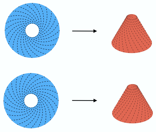
We consider rings with the nematic field forming spirals around the centre, which are initially at low temperature with , then heated [45, 46, 60]. We set , where , in cylindrical polar coordinates , and look for solutions of the form , which leads to
| (71) |
The resulting shape is a truncated right circular cone (see Figure 3).
6.2 Moderate out-of-plane deformations
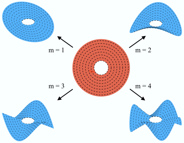
Next, we assume that the nematic director is aligned in the azimuthal direction, i.e., in cylindrical polar coordinates , and the ring is initially at high temperature with , then cooled, so that the material will tend to elongate in the azimuthal direction and contract in the radial direction. In this case, when the out-of-plane deformations are of the same order as the plate thickness, i.e., , a stability analysis similar to that carried out in [22] can be performed.
For the nematic ring, at the inner surface, where , we assume , and , such that , while at the outer surface, where , we impose , with constant, and , and also the two boundary conditions that the ‘edge’ of the plate is free from traction (see Appendix B).
We are interested in deformations with the in-plane displacement and stresses independent of , i.e., , , and , , , while the out-of-plane displacement may vary both with and , i.e., .
Under these conditions, after rescaling, so that , and denoting the ratio between inner and outer radii by , so that , we can write
| (72) |
where and represent the first derivative of and with respect to , respectively. We then solve equations (60), given the constitutive relations (43), and obtain (see Appendix C for details) the stress components
| (73) |
and the displacement components
| (74) |
for all . Such situation may arise, for example, when the ring is continuously attached to an inner disc that remains undeformed [7].
To find the out-of-plane deformations, we solve equation (59), which is equivalent to
| (75) |
where the biharmonic operator of the out-of-plane displacement in polar coordinates takes the form:
| (76) |
The four boundary conditions for equation (75) are as follows:
-
•
At the inner surface, where ,
(77) - •
Changing variable to and assuming solutions of the form , equation (75) reduces to the following fourth-order ordinary differential equation,
| (79) |
where , , , and are the derivatives of order 1, 2, 3 and 4, respectively, of with respect to , and is a control parameter.
For equation (79), the boundary conditions are:
-
•
At ,
(80) -
•
At ,
(81)
For , the ring deforms into a truncated right circular cone. For , by treating the boundary value problem as an eigenvalue problem in the control parameter , we can find the threshold value for this parameter such that a non-trivial out-of-plane deformation occurs. In this case, the evolved shapes are anti-cones (developable or d-cones) as shown in Figure 4.
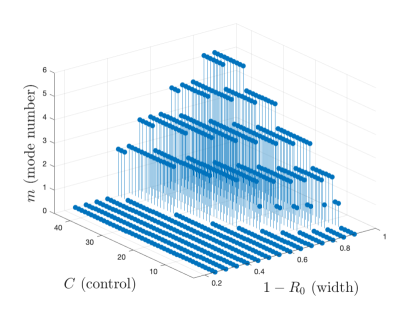
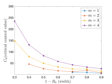
To solve equation (79), subject to the boundary conditions (80)-(81), we apply a numerical scheme described in [40, pp. 460-461]. Figure 5(a) shows the mode number observed for rings with different ratios between the inner and outer radii, , as the prescribed (control) value changes. In Figure 5(b), for mode numbers , the minimum critical control values are plotted as functions of the width, . Note that, for width , the mode number is not obtained, while for width , mode numbers and are not found.
7 Conclusion
We have developed here a Föppl-von Kármán-type model to describe the elastic behaviour of NLC plates, subject to combined optothermal stimulation and mechanical loading. We achieve this by exploiting the multiplicative decomposition of the deformation gradient into an elastic component and a ‘spontaneous’ deformation tensor. To illustrate the application of this model, we provide analytical solutions to combined natural and forced shape changes of circular rings with ‘frozen’ nematic director in circular disclination patterns, where the deformation is homogeneous through the thickness and the director remains tangent to the mid-surface.
Stress free natural shape changes had been analysed extensively from the kinematic point of view before [21, 62, 96]. However, the ability of these complex morphing materials to do physical work (which is critical in soft robotics applications, for instance) has been much less addressed [21, 77]. As interest in synthetic morphogenic materials continues to increase [16, 66], the proposed model is timely and accounts for both the displacement and stress fields in a deforming nematic plate.
Our derivation is based on the neoclassical strain-energy function describing an ideal liquid crystal solid with ‘free’ or ‘frozen’ nematic director, but the dimensional reduction procedure could, in principle, be extended to other strain-energy functions as well [28, 38, 56]. The equilibrium plate equations derived here could further be employed to tackle inverse problems where, for a target deformation, the orientation of the nematic director and the forces to be applied in the reference configuration are sought [6, 41, 65, 71, 75, 100].
Acknowledgement.
We thank Fehmi Cirak (University of Cambridge) for a discussion on constitutive modelling of liquid crystalline solids. The support by the Engineering and Physical Sciences Research Council of Great Britain under research grants EP/R020205/1 to Alain Goriely and EP/S028870/1 to L. Angela Mihai is gratefully acknowledged.
Appendix A Relations between stress tensors
In this appendix, we derive the stress tensors of the deformed nematic material in terms of the stresses in the base polymeric network when the nematic director is ‘free’ to rotate relative to the elastic matrix, and when the nematic director is ‘frozen’.
A.1 Free director
When the nematic director is ‘free’, F and n are independent variables, and the strain-energy function given by (12) takes the equivalent form
| (A.1) |
where and denote the eigenvalues and eigenvectors, respectively, of the left Cauchy-Green tensor, such that
| (A.2) |
Next, we use the multiplicative decomposition (2) of F to obtain the stress tensors of the nematic material in terms of the stresses of the elastically deformed polymeric network. Since G is symmetric, the Cauchy stress tensor for the nematic material with the strain-energy function described by (12) is calculated as follows,
| (A.3) |
where T is the elastic Cauchy stress defined by (9), , and the scalar (the hydrostatic pressure) represents the Lagrange multiplier for the internal constraint .
Note that the Cauchy stress tensor given by (A.3) is not symmetric in general [9, 76, 110]. In addition, the following condition must hold [9, 110],
| (A.4) |
or equivalently, by the principle of material objectivity stating that constitutive equations must be invariant under changes of frame of reference (see [9] for details),
| (A.5) |
The first Piola-Kirchhoff stress tensor for the nematic material is equal to
| (A.6) |
where P is the elastic first Piola-Kirchhoff stress given by (10).
The corresponding second Piola-Kirchhoff stress tensor is
| (A.7) |
where S is the elastic second Piola-Kirchhoff stress tensor given by (11).
A.2 Frozen director
If the nematic director is ‘frozen’, then the strain-energy function described by (12) can be written equivalently as follows,
| (A.8) |
where and represent the eigenvalues and eigenvectors, respectively, of the right Cauchy-Green tensor, such that
| (A.9) |
To obtain the above form, we have used the identities
| (A.10) |
The kinematic interpretation of is that it represents the square of the stretch ratio in the direction .
In this case also, we can express the stress tensors of the nematic material in terms of the stresses in the deformed polymeric network. First, we define a modified strain-energy function with independent variables F and n,
| (A.11) |
where the scalar is the Lagrange multiplier for the constraint (4).
Then, the Cauchy stress tensor for the nematic material takes the form
| (A.12) |
where T is the elastic Cauchy stress defined by (9), and is the Lagrange multiplier for the volume constraint .
As the Cauchy stress tensor given by (A.12) is not symmetric in general, the following additional condition must hold,
| (A.13) |
or equivalently,
| (A.14) |
The corresponding first Piola-Kirchhoff stress tensor for the nematic material is equal to
| (A.15) |
The associated second Piola-Kirchhoff stress tensor is
| (A.16) |
Appendix B Detailed calculations for the energy components
We provide in this appendix some detailed calculations for our derivation of the plate equations and their boundary conditions. These are standard and are included here for convenience. Similar calculations can be found in more detail in [53], for example.
First, we compute the different terms appearing in the stretching energy (28). To lowest-order, the incompressibility condition is given by
| (B.1) |
It follows that . Similarly, .
Then,
| (B.2) |
and, with defined in (38), we have
| (B.3) |
where and are given by (42) and (43), respectively. Therefore,
| (B.4) |
from which its first variation given in (56) follows.
The components of the associated Green-Lagrange strain tensor are
| (B.7) |
and the corresponding second Piola-Kirchhoff stress has the components
| (B.8) |
Therefore,
| (B.9) |
For the variation given by (58), we require the variational derivative
| (B.10) |
as well as the variational derivative of the Gaussian curvature,
| (B.11) |
We define
| (B.12) |
| (B.13) |
and
| (B.14) |
where and are the outward unit normal and the tangent vector to the boundary, respectively.
The boundary contribution in the expression of the small variation of bending energy (58) is then
| (B.15) |
In particular, when the ‘edge’ of the plate is free from traction, the variations and are arbitrary, and their coefficients in the contour integrals are equal to zero. In this case, the boundary conditions for out-of-plane deformations are
| (B.16) |
| (B.17) |
Appendix C An inflated nematic ring
Here, we derive the in-plane solution (73)-(74) for the nematic ring under the boundary conditions specified in Section 6.2. We first consider a circular ring of neo-Hookean material, with the strain-energy function described by (5). This ring occupies the reference configuration in cylindrical polar coordinates , where are constants, and deforms in a plane perpendicular to its axis (see also [40, p. 388]). In the current configuration, we have
| (C.1) |
where is a function of to be determined. For this finite deformation, the Cauchy-Green tensor is equal to
| (C.2) |
where is the first derivative of with respect to , such that the incompressibility condition is satisfied, and .
For the nematic ring described by the generalised Hooke’s law, if the in-plane displacements and stresses only depend on , then the Cauchy-Green tensor takes the approximate form (33), i.e.,
| (C.3) |
where . The associated strain components given by (34) are
| (C.4) |
It follows that the in-plane displacements are equal to
| (C.5) |
and the corresponding stresses are
| (C.6) |
Thus, assuming at the outer surface implies .
References
- [1] Agostiniani V, DeSimone A. 2017. Dimension reduction via -convergence for soft active materials, Meccanica 52, 3457-3470.
- [2] Agostiniani V, DeSimone A. 2017. Rigorous derivation of active plate models for thin sheets of nematic elastomers, Mathematics and Mechanics of Solids, 1-27.
- [3] Agostiniani V, DeSimone A, Koumatos K. 2017. Shape programming for narrow ribbons of nematic elastomers, Journal of Elasticity 127, 1-24.
- [4] Agrawal A, Luchette P, Palffy-Muhoray P, Biswal SL, Chapman WG, Verduzco R. 2012. Surface wrinkling in liquid crystal elastomers, Soft Matter 8(27), 7138-7142.
- [5] Agrawal A, Yun TH, Pesek SL, Chapman WG, Verduzco R. 2014. Shape-responsive liquid crystal elastomer bilayers, Soft Matter 10(9), 1411-1415.
- [6] Aharoni H, Sharon E, Kupferman R. 2014. Geometry of thin nematic elastomer sheets, Physical Review Letters 113, 257801.
- [7] Ahn C, Liang X, Cai S. 2015. Inhomogeneous stretch induced patterning of molecular orientation in liquid crystal elastomers, Extreme Mechanics Letters 5, 30-36.
- [8] Ahn Sk, Ware TH, Lee KM, Tondiglia VP, White TJ. 2016. Photoinduced topographical feature development in blueprinted azobenzene-functionalized liquid crystalline elastomers, Advanced Functional Materials 26, 5819-5826.
- [9] Anderson DR, Carlson DE, Fried E. 1999. A continuum-mechanical theory for nematic elastomers, Journal of Elasticity 56, 33-58 (doi: 10.1023/A:1007647913363).
- [10] Biggins JS, Warner M. 2009. Supersoft elasticity in polydomain nematic elastomers, Physical Review Letters 103, 037802 (doi: 10.1103/PhysRevLett.103.037802).
- [11] Biggins JS, Warner M, Bhattacharya. 2012. Elasticity of polydomain liquid crystal elastomers, Journal of the Mechanics and Physics of Solids 60, 573-590 (doi: 10.1016/j.jmps.2012.01.008).
- [12] Bladon P, Terentjev EM, Warner M. 1994. Deformation-induced orientational transitions in liquid crystal elastomers, Journal de Physique II 4, 75-91.
- [13] Brömmel F, Zou P, Finkelmann H, Hoffmann A. 2013. Influence of the mesogenic shape on the molecular dynamics and phase-biaxiality of liquid crystal main-chain polymer, Soft Matter 9(5), 1674-1677.
- [14] Camacho-Lopez M, Finkelmann H, Palffy-Muhoray P, Shelley M. 2004. Fast liquid-crystal elastomer swims into the dark, Nature Materials 3, 307-310 (doi: 10.1038/nmat1118).
- [15] Ciarlet PG. 1980. A justification of the von Kármán equations, Archive of Rational Mechanics and Analysis 73, 349-389.
- [16] Cicconofri G, Arroyo M, Noselli G, DeSimone A. 2020. Morphable structures from unicellular organisms with active, shape-shifting envelopes: Variations on a theme by Gauss, International Journal of Non-Linear Mechanics 118, 103278.
- [17] Cirak F, Long Q, Bhattacharya K, Warner M. 2014. Computational analysis of liquid crystalline elastomer membranes: Changing Gaussian curvature without stretch energy, International Journal of Solids and Structures 51(1), 144-153 (doi: 10.1016/j.ijsolstr.2013.09.019).
- [18] Corbett D, Warner M. 2008. Bleaching and stimulated recovery of dyes and of photocantilevers, Physical Review E 77, 051710.
- [19] Davidson EC, Kotikian A, Li S, Aizenberg J, Lewis JA. 2019. 3D printable and reconfigurable liquid crystal elastomers with light-induced shape memory via dynamic bond exchange, Advanced Materials, 1905682 (doi: 10.1002/adma.201905682).
- [20] de Gennes PG. 1975. Physique moléculaire - réflexions sur un type de polymères nématiques, Comptes rendus de l’Académie des Sciences B 281, 101-103.
- [21] de Haan LT, Schenning AP, Broer DJ. 2014. Programmed morphing of liquid crystal networks, Polymer 55(23), 5885-5896 (doi: 10.1016/j.polymer.2014.08.023).
- [22] Dervaux J, Ben Amar M. 2008. Morphogenesis of growing soft tissues, Physical Review Letters 101, 068101.
- [23] Dervaux J, Ciarletta P, Ben Amar M. 2009. Morphogenesis of thin hyperelastic plates: A constitutive theory of biological growth in the Föoppl-von Káarmán limit, Journal of the Mechanics and Physics of Solids 57, 458-471.
- [24] DeSimone A. 1999. Energetics of fine domain structures, Ferroelectrics 222(1), 275-284 (doi: 10.1080/00150199908014827).
- [25] DeSimone A, Dolzmann G. 2000. Material instabilities in nematic elastomers, Physica D 136(1-2), 175-191 (doi: S0167-2789(99)00153-0).
- [26] DeSimone A, Dolzmann G. 2002. Macroscopic response of nematic elastomers via relaxation of a class of SO(3)-invariant energies, Archive of Rational Mechanics and Analysis 161, 181-204 (doi: 10.1007/s002050100174).
- [27] DeSimone A, Gidoni P, Noselli G. 2015. Liquid crystal elastomer strips as soft crawlers, Journal of the Mechanics and Physics of Solids 84, 254-272.
- [28] DeSimone A, Teresi L. 2009. Elastic energies for nematic elastomers, The European Physical Journal E 29, 191-204 (doi: 10.1140/epje/i2009-10467-9).
- [29] Efrati E, Sharon E, Kupferman R. 2009. Buckling transition and boundary layer in non-Euclidean plates, Physical Review E 80, 016602.
- [30] Efrati E, Sharon E, Kupferman R. 2013. The metric description of elasticity in residually stressed soft materials, Soft Matter 9, 8187 (doi: 0.1039/c3sm50660f).
- [31] Erbay HA. 1997. On the asymptotic membrane theory of thin hyperelastic plates, International Journal of Engineering Science 35(2), 151-170.
- [32] Finkelmann H, Greve A, Warner M. 2001. The elastic anisotropy of nematic elastomers, The European Physical Journal E 5, 281-293 (doi: 10.1007/s101890170060).
- [33] Finkelmann H, Kock HJ, Rehage G. 1981. Investigations on liquid crystalline polysiloxanes 3, Liquid crystalline elastomers - a new type of liquid crystalline material, Die Makromolekulare Chemie, Rapid Communications 2, 317-322 (doi: 10.1002/marc.1981.030020413).
- [34] Finkelmann H, Nishikawa E, Pereita GG, Warner M. 2001. A new opto-mechanical effect in solids, Physical Review Letters 87(1), 015501 (doi:10.1103/PhysRevLett.87.015501).
- [35] Flory PJ. 1961. Thermodynamic relations for high elastic materials, Transactions of the Faraday Society 57, 829-838 (doi: 10. 1039/TF9615700829).
- [36] Föppl A. 1907. Vorlesungen über Technische Mechanik, B.G. Teubner, Leipzig.
- [37] Ford MJ, Ambulo CP, Kent TA, Markvicka EJ, Pan C, Malen J, Ware TH, Majidi C. 2019. A multifunctional shape-morphing elastomer with liquid metal inclusions, Proceedings of the National Academy of Sciences 116(43), 21438-21444 (doi: 10.1073/pnas.1911021116).
- [38] Fried E, Sellers S. 2004. Free-energy density functions for nematic elastomers, Journal of the Mechanics and Physics of Solids 52(7), 1671-1689 (doi: 10.1016/j.jmps.2003.12.005).
- [39] Gelebart AH, Mulder DJ, Varga M, Konya A, Vantomme G, Meijer EW, Selinger RLB, Broer DJ. 2017. Making waves in a photoactive polymer film, Nature 546, 632.
- [40] Goriely A. 2017. The Mathematics and Mechanics of Biological Growth, Springer-Verlag, New York.
- [41] Griniasty I, Aharoni H, Efrati E. 2019. Curved geometries from planar director fields: Solving the two-dimensional inverse problem, Physical Review Letters 123, 127801.
- [42] Haghiashtiani G, Habtour E, Park SH, Gardea F, McAlpine MC. 2018. 3D printed electrically-driven soft actuators, Extreme Mechanics Letters 21, 1-8 (doi: 10.1016/j.eml.2018.02.002).
- [43] Huang ZY, Hong W, Suo Z. 2005. Nonlinear analyses of wrinkles in a film bonded to a compliant substrate, Journal of the Mechanics and Physics of Solids 53, 2101-2118.
- [44] Kaiser A, Winkler M, Krause S, Finkelmann H, Schmidt AM. 2009. Magnetoactive liquid crystal elastomer nanocomposites, Journal of Materials Chemistry 19(4), 538–543.
- [45] Kassianidis F, Ogden RW, Merodio J, Pence TJ. 2008. Azimuthal shear of a transversely isotropic elastic solid, Mathematics and Mechanics of Solids 13, 690-724 (doi: 0.1177/1081286507079830).
- [46] Klein Y, Efrati E, Sharon E. 2007. Shaping of elastic sheets by prescription of non-euclidean metrics, Science 315, 1116-1120 (doi:10.1126/science.1135994).
- [47] Konya A, Gimenez-Pinto V, Selinger RLB. 2016. Modeling defects, shape evolution, and programmed auto-origami in liquid crystal elastomers, Frontiers in Materials 3, 24 (doi: 10.3389/fmats.2016.00024).
- [48] Kowalski BA, Mostajeran C, Godman NP, Warner M, White TJ. 2017. Curvature by design and on demand in liquid crystal elastomers, Physical Review E 97, 012504.
- [49] Krieger MS, Dias MA. 2019. Tunable wrinkling of thin nematic liquid crystal elastomer sheets, Physical Review E 100, 022701 (doi: 10.1103/PhysRevE.100.022701).
- [50] Kuenstler AS. Hayward RC. 2019. Light-induced shape morphing of thin films, Current Opinion in Colloid & Interface Science 40, 70-86 (doi: 10.1016/j.cocis.2019.01.009).
- [51] Küpfer J, Finkelmann H. 1991. Nematic liquid single crystal elastomers, Die Makromolekulare Chemie, Rapid Communications 12, 717-726.
- [52] Küpfer J, Finkelmann H. 1994. Liquid crystal elastomers: Influence of the orientational distribution of the crosslinks on the phase behavior and reorientation processes, Macromolecular Chemistry and Physics 195, 1353-1367.
- [53] Landau LD, Lifshitz EM. 1986. Theory of Elasticity, Volume 7 of Course of Theoretical Physics, 3rd revised ed, Pergamon Press, New York.
- [54] Love AEH. 1888. VI. The small free vibrations and deformation of a thin elastic shell, Philosophical Transactions of the Royal Society 179, 491-546.
- [55] Lubarda VA. 2004. Constitutive theories based on the multiplicative decomposition of deformation gradient: thermoelasticity, elastoplasticity and biomechanics, Applied Mechanics Reviews 57(2), 95-108 (doi: 10.1115/1.1591000).
- [56] Mihai LA, Goriely A. 2020. Likely striping in stochastic nematic elastomers, Mathematics and Mechanics of Solids, 1-22 (doi: 0.1177/1081286520914958).
- [57] Mihai LA, Goriely A. 2017. How to characterize a nonlinear elastic material? A review on nonlinear constitutive parameters in isotropic finite elasticity, Proceedings of the Royal Society A 473, 20170607 (doi: 10.1098/rspa.2017.0607).
- [58] Mistry D, Gleeson HF. 2019. Mechanical deformations of a liquid crystal elastomer at director angles between 0∘ and 90∘: Deducing an empirical model encompassing anisotropic nonlinearity, Journal of Polymer Science 57, 1367-1377 (doi: 0.1002/polb.24879).
- [59] Modes CD, Bhattacharya K, Warner M. 2010. Disclination-mediated thermo-optical response in nematic glass sheets, Physical Review E 81, 060701(R).
- [60] Modes CD, Bhattacharya K, Warner M. 2011. Gaussian curvature from flat elastica sheets, Proceedings of the Royal Society A 467, 1121-1140 (doi:10.1098/rspa.2010.0352).
- [61] Modes CD, Warner M. 2011. Blueprinting nematic glass: Systematically constructing and combining active points of curvature for emergent morphology, Physical Review E 84, 021711.
- [62] Modes C, Warner M. 2016. Shape-programmable materials, Physics Today 69, 32-38.
- [63] Mori T, Cukelj R, Prévôt ME, Ustunel S, Story A, Gao Y, Diabre K, McDonough JA, Johnson Freeman E, Hegmann E, Clements RJ. 2020. 3D porous liquid crystal elastomer foams supporting long-term neuronal cultures, Macromolecular Rapid Communications, 1900585 (doi: 10.1002/marc.201900585).
- [64] Mostajeran C. 2015. Curvature generation in nematic surfaces, Physical Review E 91, 062405.
- [65] Mostajeran C, Warner M, Ware TH, White TJ. 2016. Encoding Gaussian curvature in glassy and elastomeric liquid crystal solids, Proceedings of the Royal Society A 472, 20160112 (doi:10.1098/rspa.2016.0112).
- [66] Noselli G, Arroyo M, DeSimone A. 2019. Smart helical structures inspired by the pellicle of euglenids, Journal of the Mechanics and Physics of Solids 123, 234-246.
- [67] Ogden RW. 1997. Non-Linear Elastic Deformations, 2nd ed, Dover, New York.
- [68] Pang X, Lv Ja., Zhu C, Qin L, Yu Y. 2019. Photodeformable azobenzene-containing liquid crystal polymers and soft actuators, Advanced Materials, 1904224 (doi: 10.1002/adma.201904224).
- [69] Pismen LM. 2014. Metric theory of nematoelastic shells, Physical Review E 90, 060501(R).
- [70] Plucinsky P, Bhattacharya K. 2017. Microstructure-enabled control of wrinkling in nematic elastomer sheets, Journal of the Mechanics and Physics of Solids 102, 125-150 (doi: 10.1016/j.jmps.2017.02.009).
- [71] Plucinsky P, Lemm M, Bhattacharya K. 2016. Programming complex shapes in thin nematic elastomer and glass sheets, Physical Review E 94, 010701(R).
- [72] Prévôt ME, Andro H, Alexander SLM, Ustunel S, Zhu C, Nikolov Z, Rafferty ST, Brannum MT, Kinsel B, Korley LTJ, Freeman EJ, McDonough JA, Clements RJ, Hegmann E. 2018. Liquid crystal elastomer foams with elastic properties specifically engineered as biodegradable brain tissue scaffolds, Soft Matter 14, 354-360 (doi: 10.1039/c7sm01949a).
- [73] Sawa Y,Ye F, Urayama K, Takigawa T, Gimenez-Pinto V, Selinger RLB, Selingerb JV. 2011. Shape selection of twist-nematic-elastomer ribbons, Proceedings of the National Academy of Sciences 108(16), 6364–6368.
- [74] Sawa Y, Urayama K, Takigawa T, Gimenez-Pinto V, Mbanga BL, Ye F, Selinger JV, Selingerb RLB. 2013. Shape and chirality transitions in off-axis twist nematic elastomer ribbons, Physical Review E 88, 022502.
- [75] Siéfert E, Reyssat E, Bico J, Roman B. 2019. Bio-inspired pneumatic shape-morphing elastomers, Nature Materials 18, 24-29.
- [76] Soni H, Pelcovits RA, Powers TR. 2016. Wrinkling of a thin film on a nematic liquid-crystal elastomer, Physical Review E 94, 012701 (doi: 10.1103/PhysRevE.94.012701).
- [77] Tajbakhsh AR, Terentjev EM. 2001. Spontaneous thermal expansion of nematic elastomers, The European Physical Journal E 6, 181–188.
- [78] Tian H, Wang Z, Chen Y, Shao J, Gao T, Cai S, 2018. Polydopamine-coated main-chain liquid crystal elastomer as optically driven artificial muscle, ACS Applied Materials & Interfaces 10(9), 8307-8316 (doi: 10.1021/acsami.8b00639).
- [79] Tomassetti G, Varano V. 2017. Capturing the helical to spiral transitions in thin ribbons of nematic elastomers, Meccanica 52, 3431-3441.
- [80] Torras N, Zinoviev KE, Marshall JE, Terentjev EM, Esteve J. 2011. Bending kinetics of a photo-actuating nematic elastomer cantilever, Applied Physics Letters 99, 254102 (doi: 10.1063/1.3670502).
- [81] Tottori S, Zhang L, Qiu FM, Krawczyk KK, Franco-Obregón A, Nelson BJ. 2012. Magnetic helical micromachines: fabrication, controlled swimming, and cargo transport, Advanced Materials 24(6), 811-816.
- [82] Treloar LRG. 1944. Stress-strain data for vulcanized rubber under various types of deformation, Transactions of the Faraday Society 40, 59-70.
- [83] Treloar LRG. 2005. The Physics of Rubber Elasticity, 3rd ed, Oxford University Press, Oxford, UK.
- [84] Truesdell C, Noll W. 2004. The Non-Linear Field Theories of Mechanics, 3rd ed, Springer-Verlag, New York.
- [85] Ula SW, Traugutt NA, Volpe RH, Patel RP, Yu K, Yakacki CM. 2018. Liquid crystal elastomers: an introduction and review of emerging technologies, Liquid Crystals Review 6, 78-107 (doi: 10.1080/21680396.2018.1530155).
- [86] Uruyama K. 2013. Switching shapes of nematic elastomers with various director configurations, Reactive & Functional Polymers 73, 885-890.
- [87] Urayama K, Honda S, Takigawa T. 2005. Electrically driven deformations of nematic gels, Physical Review E 71, 051713.
- [88] Urayama K, Honda S, Takigawa T. 2006. Deformation coupled to director rotation in swollen nematic elastomers under electric fields, Macromolecules 39, 1943-1949.
- [89] van Oosten CL, Harris KD, Bastiaansen CWM, Broer DJ. 2007. Glassy photomechanical liquid-crystal network actuators for microscale devices, The European Physical Journal E 23(3), 329-33.
- [90] Verwey GC, Warner M, Terentjev EM. 1996. Elastic instability and stripe domains in liquid crystalline elastomers, Journal de Physique 6(9), 1273-1290 (doi: 10.1051/jp2:1996130).
- [91] von Kármán T. 1910. Festigkeitsproblem im Maschinenbau, Encyklopadie der Mathematischen Wissenschaftler 4, 311-385.
- [92] Wan G, Jin C, Trase I, Zhao S, Chen Z. 2018. Helical structures mimicking chiral seedpod opening and tendril coiling, Sensors 18(9), 2973 (doi: 10.3390/s18092973).
- [93] Wang Z, He Q, Wang Y, Cai S. 2019. Programmable actuation of liquid crystal elastomers via living exchange reaction, Soft Matter 15(13), 2811-2016.
- [94] Wang Z, Tian H, He Q, Cai S. 2017. Reprogrammable, reprocessible, and self-healable liquid crystal elastomer with exchangeable disulfide bonds, ACS Applied Materials & Interfaces 9(38), 33119-33128 (doi: 10.1021/acsami.7b09246).
- [95] Ware TH, McConney ME, Wie JJ, Tondiglia VP, White TJ. 2015. Voxelated liquid crystal elastomers, Science 347, 982-984.
- [96] Warner M. 2020. Topographic mechanics and applications of liquid crystalline solids, Annual Review of Condensed Matter Physics 11, 125-145 (doi: 10.1146/annurev-conmatphys-031119-050738).
- [97] Warner M, Bladon P, Terentjev E. 1994. “Soft elasticity” - deformation without resistance in liquid crystal elastomers, Journal de Physique II 4, 93-102 (doi: 10.1051/jp2:1994116).
- [98] Warner M, Gelling KP, Vilgis TA. 1988. Theory of nematic networks, The Journal of Chemical Physics 88, 4008-4013.
- [99] Warner M, Modes CD, Corbett D. 2010. Curvature in nematic elastica responding to light and heat, Proceedings of the Royal Society A 466, 2975-2989 (doi:10.1098/rspa.2010.0135).
- [100] Warner M, Mostajeran C. 2018. Nematic director fields and topographies of solid shells of revolution, Proceedings of the Royal Society A 474, 20170566.
- [101] Warner M, Terentjev EM. 1996. Nematic elastomers - a new state of matter?, Progress in Polymer Science 21, 853-891.
- [102] Warner M, Terentjev EM. 2007. Liquid Crystal Elastomers, paper back, Oxford University Press, Oxford, UK.
- [103] Warner M, Wang, XJ. 1991. Elasticity and phase behavior of nematic elastomers, Macromolecules 24, 4932-4941 (doi: 10.1021/ma00017a033).
- [104] Wei J, Yu Y. 2012. Photodeformable polymer gels and crosslinked liquid-crystalline polymers, Soft Matter 8(31), 8050-8059.
- [105] White TJ, Broer DJ. 2015. Programmable and adaptive mechanics with liquid crystal polymer networks and elastomers, Nature Materials 14, 1087-1098 (doi:10.1038/nmat4433).
- [106] Wie JJ, Shankar MR, White TJ. 2016. Photomotility of polymers, Nature Communications 7, 13260.
- [107] Winkler M, Kaiser A, Krause S, Finkelmann H, Schmidt AM. 2010. Liquid crystal elastomers with magnetic actuation, Macromolecular Symposia 291-292(1), 186-192.
- [108] Xu F, Fu C, Yang Y. 2020. Water affects morphogenesis of growing aquatic plant leaves, Physical Review Letter 124, 038003.
- [109] Zentel R. 1986. Shape variation of cross-linked liquid-crystalline polymers by electric fields, Liquid Crystals 1, 589-592.
- [110] Zhang Y, Xuan C, Jiang Y, Huo Y. 2019. Continuum mechanical modeling of liquid crystal elastomers as dissipative ordered solids, Journal of the Mechanics and Physics of Solids 126, 285-303.
- [111] Zhao D, Liu Y. 2020. Light-induced spontaneous bending of a simply supported liquid crystal elastomer rectangular plate, Physical Review E 101, 042701.