Reversible vs. irreversible voltage manipulation of interfacial magnetic anisotropy in Pt/Co/oxide multilayers
Abstract
The perpendicular magnetic anisotropy at the Co/oxide interface in Pt/Co/MOx (MOx = MgOx, AlOx, TbOx) was modified by an electric field using a 10 nm-thick ZrO2 as a solid electrolyte. The large voltage-driven modification of interfacial magnetic anisotropy and the non-volatility of the effect is explained in terms of the migration of oxygen ions towards/away from the Co/MOx interface. While the effect is reversible in Pt/Co/AlOx and Pt/Co/TbOx, where the Co layer can be oxidised or reduced, in Pt/Co/MgOx the effect has been found to be irreversible. We propose that these differences may be related to the different nature of the ionic conduction within the MOx layers.
pacs:
75.70.Ak, 75.60.JkI Introduction
The manipulation of the interfacial magnetic anisotropy via an electric-field is an active field of research, as it is a promising route towards the realisation of low power spintronic devices Nozaki et al. (2019). In metallic ferromagnetic (FM) thin films, electric fields have been shown to modify substantially the interface magnetic anisotropy energy through the modification of the electron density of states at the Fermi energy, despite their short penetration depth limited by Coulomb screening Weisheit et al. (2007); Maruyama et al. (2009); Shiota et al. (2011); Matsukura et al. (2015). The perpendicular magnetic anisotropy (PMA) at a FM/oxide interface can be as large as the one found at a heavy metal/Co interface Monso et al. (2002). Ab initio calculations suggest that this anisotropy results from the hybridisation of the oxygen and transition metal electronic orbitals across the interface Nozaki et al. (2019). Several experimental studies of Pt/Co/MOx trilayers (M = Al, Mg, Ta, etc) showed that the PMA amplitude is related to the degree of oxidation of the Co layer. The interfacial anisotropy constant (K) at the Co/MOx interface has a characteristic bell-like shape, with a maximum for the optimal oxidation conditions (see sketch in Fig. 1), obtained when the oxygen atoms reach the Co-M interface, so that Co-O bonds prevail over Co-M bonds Manchon et al. (2008a, b, c); Dieny and Chshiev (2017). It is then not surprising that the largest effects of electric-field on the PMA (Ks/E=1000 fJ/Vm) have been obtained by triggering the migration of oxygen ions towards/away from the FM/oxide interface Bi et al. (2014); Bauer et al. (2015); Zhou et al. (2016). This magneto-ionic effect, obtained in most cases using Gd2O3 as dielectric oxide layer, leads to a non-volatile modification of the interfacial PMA, as opposed to the volatile effect obtained by electron accumulation/depletion. Also, the timescales associated with electric field induced displacement of electrons or ions are different.
In the present work, we describe the effect of an electric field on the interfacial PMA in a series of Pt/Co/MOx (M=Mg, Al, Tb) trilayers. Beyond their interest because of their tunable PMA, these non-centrosymmetric systems have been largely studied because they can host chiral magnetic textures such as chiral domain walls (DWs) and magnetic skyrmions, due to the presence of interfacial Dzyaloshinskii-Moriya interaction (DMI). It has been shown that, by tuning the PMA Bauer et al. (2012, 2013); Chiba et al. (2012); Schellekens et al. (2012); Lin et al. (2016); Bernand-Mantel et al. (2013); Schott et al. (2016) and/or the DMI at the FM/oxide interface, Srivastava et al. (2018); Herrera Diez et al. (2019); Koyama et al. (2018) the electric fields can modify the stability and the field- and current- driven dynamics of such magnetic textures.
Using a 10 nm thick ZrO2 as dielectric layer, we demonstrate that the effect of the electric field on the PMA is large (1200 fJ/Vm at room temperature) and non-volatile. Tuning the magnetic anisotropy allowed us to stabilise a variety of magnetic configurations within the Co layers and to modify the details of the magnetic reversal mechanisms. The non-volatility of the magnetic configurations obtained after the removal of the gate voltage, the characteristic time evolution of the electric field effect and its large efficiency can be understood by considering the ZrO2 as a solid electrolyte working as an oxygen ion conductor. While the effect is reversible in Pt/Co/AlOx and Pt/Co/TbOx, where the Co layer can be oxidised or reduced, in Pt/Co/MgOx the effect has been found to be irreversible. Once the PMA has increased by increasing the Co oxidation, the reverse process does not occur by polarisation inversion. We propose that this different behaviour may be related to the different nature of the ionic conduction within the MOx layer.
II Methods: film deposition and patterning
Pt(3)/Co(1)/Mg(0.7), Pt(3)/Co(1)/Al(1) and Pt(3)/Co(1.1-1.2)/Tb(0.6) trilayers (thicknesses in nm) were deposited by magnetron sputtering on Si/SiO2 wafers. The Mg and Tb layers were oxidised in oxygen atmosphere while Al layer was oxidised in an oxygen plasma at room temperature. The trilayers were patterned into 1-50 m wide strips by electron beam lithography and ion beam milling. A 10 nm thick ZrO2 dielectric layer was then deposited on top of the samples by atomic layer deposition (ALD). Finally, following a second lithography step, a 6 nm thick Pt layer was evaporated on top of the strips, leading to a local gate. In the three magnetic stacks the Co layer was under-oxidised relative to the optimal oxidation corresponding to the maximum PMA (see Manchon et al. (2008a, b, c); Dieny and Chshiev (2017) and sketches in Figs.1-3). For more details of the fabrication see the Supplemental Material.
The electric field is applied across the Pt electrodes, with the top one being grounded. The bias voltage is defined as Vg = Vtop - Vbottom, in order to keep the usual sign convention. Unless specified, the bias voltage was applied with the sample being at room temperature. The magnetic configuration of the Co layer below the electrode regions was observed with magnetic force microscopy (MFM) for Pt/Co/MgOx and Pt/Co/TbOx and by polar magneto-optical Kerr microscopy for Pt/Co/AlOx. The hysteresis loops were measured by polar magneto-optical Kerr effect (MOKE). Note that the hysteresis loops and the magnetic images were measured always with Vg = 0, either in the initial state or after the application of the electric field, once Vg had been removed and the new magnetic state was imprinted in the Co layer.
III Non volatile and irreversible manipulation of interfacial PMA in Pt/Co/MgOx
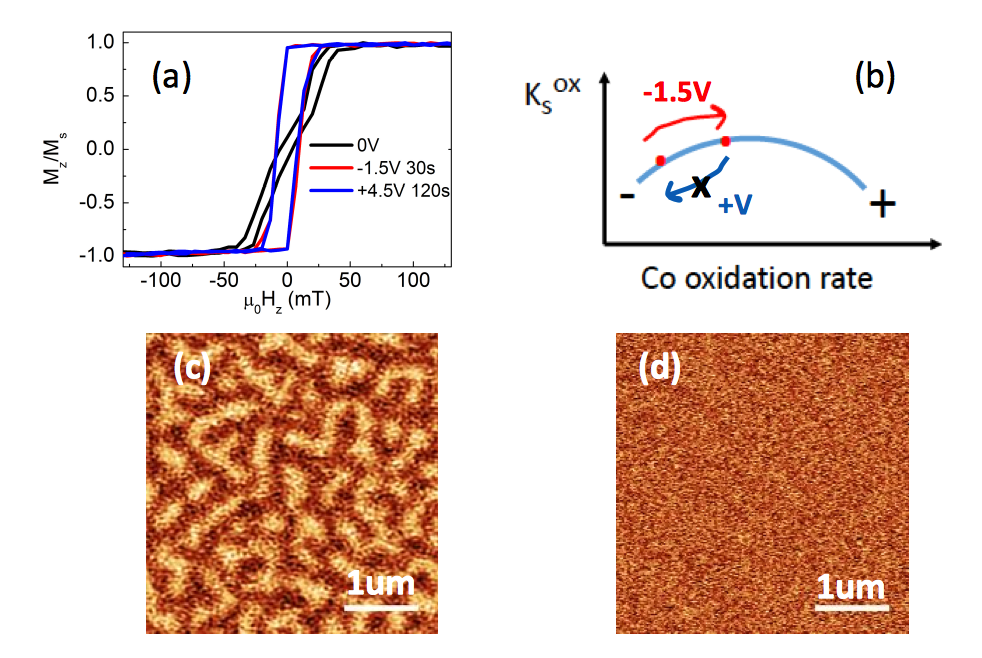
The hysteresis loop measured for the Pt/Co/MgOx trilayer exhibits a butterfly-like shape with low remanence, indicating thermally activated formation of magnetic domains (Fig. 1(a)). The MFM image confirms the presence of labyrinthine domains with out-of-plane magnetisation, with an average width of 120nm (Fig. 1(c)).
The formation of labyrinthine domains is the consequence of the balance between demagnetising energy and domain wall energy in a perpendicularly magnetised system. This magnetic configuration can be observed in the vicinity of the reorientation transition from in-plane (IP) to out-of-plane (OOP) magnetisation, when the effective magnetic anisotropy is close to zero and changes sign:
| (1) |
where is the interfacial anisotropy constant, with and the contributions from the Co/Pt and Co/MOx interfaces and is the spontaneous magnetisation.
The labyrinthine domain width in the case of ultrathin ferromagnetic layers is given by Hubert and Schäfer (1998); Kaplan and Gehring (1993):
| (2) |
where is the characteristic dipolar length; is the domain wall energy, is the ferromagnetic film thickness and is a numerical constant of the order of 1. In the non-centrosymmetric stacks studied in this work, domain walls have chiral Néel structure Boulle et al. (2016); Juge et al. (2019) and their energy is given , where is the exchange stiffness and is the strength of the Dzyaloshinskii-Moriya interaction. The observed labyrinthine structure can be reproduced by micromagnetic simulations using experimentally relevant magnetic parameters (see Supplemental Material).
After the application of a bias voltage =-1.5 V for 30 seconds, the stripe domains disappear and a magnetic state with 100% remanence at zero field is obtained, as shown by the square hysteresis loop (Fig. 1(a)) and the MFM image (Fig. 1(d)). This indicates that the negative voltage drives the increase of the interfacial anisotropy anisotropy which, as shown in Fig. 1(c)), can be associated to the increase of the Co oxidation. The same magnetic state is maintained for several weeks after the removal of the electric field i.e. the change of magnetic properties driven by the electric field can be defined as non-volatile. Fig. 1(a) shows that after the application of a reverse voltage =+4.5 V for 2 minutes, the hysteresis loop stays unchanged. In order to confirm the irreversibility of the electric-field effect, a much larger bias voltage (=+12 V) was also applied for several minutes and the sample temperature was increased up to 200°C during the electric field application. For positive voltages, whatever the condition, the hysteresis loops remained square i.e. the electric field effect appears to be irreversible.
IV Non-volatile and reversible manipulation of interfacial PMA in Pt/Co/AlOx
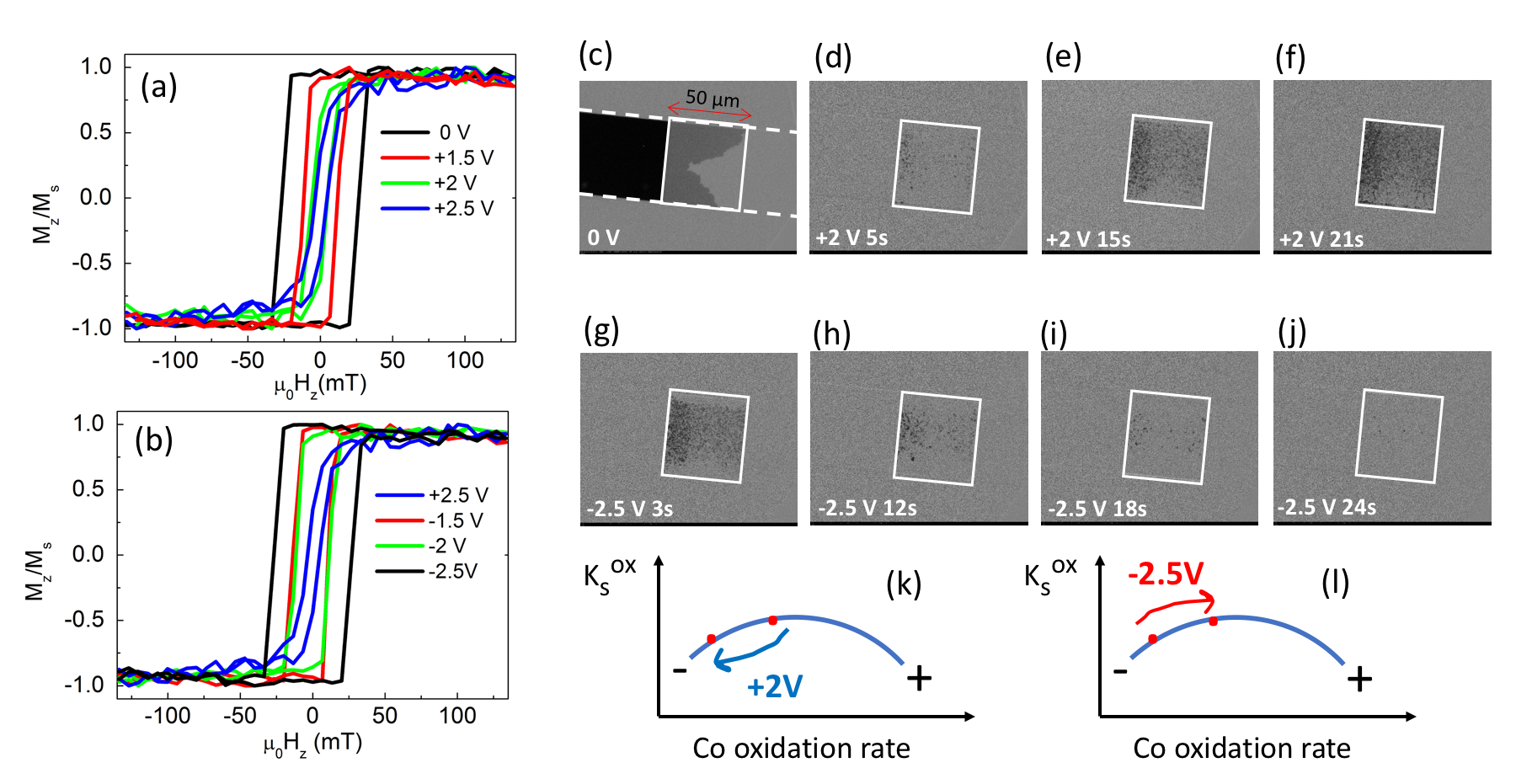
In the initial state, the Co layer in Pt/Co/AlOx presents an out-of-plane magnetisation, with a square hysteresis loop showing a saturated magnetic state at remanence (Fig. 2(a)). Following the application of positive voltages ranging from +1.5 V to +2.5 V for 30 seconds, the hysteresis loops (always measured after the voltage was removed, Vg=0) illustrate a progressive decrease of the coercive field, indicating a decrease of the interfacial PMA. As shown in Fig. 2(k), this points to a decrease of the oxidation of the Co layer. When the reverse voltage is applied (from -1.5 V to -2.5V for 30 seconds, Fig. 2(b)) the opposite process occurs: the gradual widening of the hysteresis loops suggests the increase of PMA, related to the increase of the Co oxidation (Fig. 2(l)) up to the recovery of an hysteresis loop with a coercive field similar to the initial one. The effect is therefore non-volatile and reversible.
The modification of the interfacial PMA can also be deduced from the voltage-induced variation of the magnetisation reversal process, as illustrated by the differential MOKE microscopy images shown in Fig. 2(c-j). In the initial state (Fig. 2(c)) the magnetisation reversal occurs via the expansion of a few large domains, as expected in magnetic layers with sufficiently large anisotropy. The magnetic configurations shown in Fig. 2(d-j) were obtained as follows: after the application of a bias voltage =2 V for a time t from 2 to 24 s, the samples were magnetically saturated in the OOP direction with a field +. A 20 ms long, 26 mT strong pulse - was then applied to reverse the magnetisation. The images show that after the application of a positive voltage =+2 V, the magnetisation reversal mechanism changes and is dominated by the nucleation of a large density of domains, the domain density increasing as the application time of the voltage increases. This may be explained within the droplet model Barbara and Uehara (1978) that predicts that the height of the energy barrier for nucleation is , where is the domain wall energy, is the film thickness and is the applied magnetic field Vogel et al. (2006). Since decreases when the effective anisotropy decreases, nucleation may dominate the magnetisation reversal in disordered samples with low average magnetic anisotropy, where the large distribution of anisotropy fields (i.e. of local defects) may hinder the domain wall movement. As the application time of the positive voltage increases, the PMA progressively decreases, leading to an increase of the density of the reversed domains Labrune et al. (1989); Pommier et al. (1990). Note that no nucleation event is observed outside the electrode region, where the PMA remains large and the applied field pulse is not sufficient to overcome the nucleation barriers. When the negative bias voltage is applied for increasing times, starting from the configuration with the lowest PMA (Fig. 2(d)), the density of reverse domains gradually decreases, in agreement with the increase of the PMA suggested by the hysteresis loops.
V Non-volatile and reversible manipulation of interfacial PMA in Pt/Co/TbOx
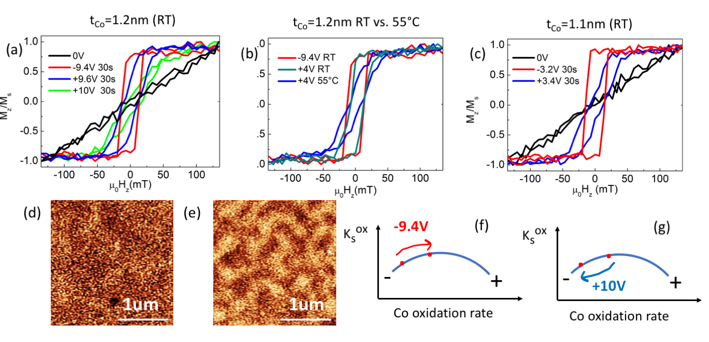
Fig. 3(a) shows the polar MOKE hysteresis loops acquired for Pt/Co/TbOx in a sample region with =1.2 nm. Before applying the electric field, the loop is tilted, as expected for in-plane magnetisation. After the application of a bias voltage =-9.4 V for 30 s, the hysteresis loop becomes square indicating the increase of PMA and the switch to a remanent saturated out-of-plane magnetisation. By applying an opposite voltage (=+9.6 V for 30 s) the anisotropy decreases, giving rise to a loop reminiscent of the presence of labyrinthine domains in zero field. When =+10 V is applied for 30 s, the anisotropy can be further decreased leading to in-plane magnetisation orientation as in the initial state.
The voltage-induced modification of the magnetisation state is non volatile and, like for Pt/Co/AlOx, the interfacial magnetic anisotropy can be tuned in a reversible way.
The MFM images shown in Fig. 3(d-e) confirm the modification of the magnetic configuration by the electric-field. The image with homogenous contrast observed after the application of =-9.4 V for 30 s (Fig. 3(d)) confirms the saturated magnetic state at remanence already indicated by the hysteresis loop. After the application of =+10 V for 30 s (butterfly-like hysteresis loop in Fig. 3(a)), the presence of demagnetised state with labyrinthine domains is in agreement with the decrease of the interfacial PMA.
If the sample temperature is increased to 55°C during the application of the electric field, the voltage necessary to switch between in-plane and out-of-plane magnetisation is of the order of -4 V for 30 s, to be compared to -9.4 V for 30 s at room temperature (Fig. 3(b)). The kinetics of the oxidation process is therefore enhanced by the temperature.
When the bias voltage is applied to the sample with a thinner Co layer (=1.1 nm), the voltage necessary to switch the magnetisation from in-plane to out-of-plane at room temperature is reduced to =-3.4 V for 30 s (Fig. 3(c)). This results can be related to the 1/ dependence of the interfacial magnetic anisotropy energy (Eq. 1).
VI Discussion: microscopic mechanisms
Our results show that the interfacial magnetic anisotropy at the Co/MOx interface in Pt/Co/MOx trilayers can be strongly modified by a gate voltage, using a 10nm thick Zr dieletric layer deposited by ALD on top of the magnetic stack. A negative/positive gate voltage leads to an increase/decrease of the PMA, which we correlate with an increase/decrease of the oxidation of the initially under-oxidised Co layers. The efficiency of the effect has been measured to be 1200 fJ/Vm for Pt/Co/AlOx at room temperature (see Supplemental Material) and similar values can be expected for Pt/Co/TbOx and Pt/Co/MgOx. These values are comparable to the highest reported in the literature in cases where the gate voltage applied at high temperature triggered oxygen ion migration Bi et al. (2014); Bauer et al. (2015) or where the sample was hydrated giving rise to charge conduction dominated by hydrogen ions Tan et al. (2019a, b). In all these cases, Gd2O3 was used as an ion conductor layer.
In Pt/Co/AlOx and Pt/Co/TbOx, the non-volatility and the reversibility of the effect, the large voltage-induced modification of the interfacial PMA at the Co/oxide interface and its dependence on the strength or the duration of the applied voltage suggests that the driving mechanism might be the migration of oxygen ions across the ZrO2 dielectric layer.
Negative/positive gate voltages, driving O2- ions towards/away from the Co layer, would lead to an increase/decrease of the Co oxidation. Since the Co layers are initially under-oxidised with respect to the optimal oxidation, that should give rise to an increase/decrease of the interfacial anisotropy, as observed experimentally (see the sketches in Fig. 1(b), Fig. 2(k,l) and Fig. 3(f,g)). These features therefore confirm, as found by previous works Manchon et al. (2008a, b, c); Bernand-Mantel et al. (2013) that the modification of the observed PMA is associated with variation of the oxidation of the Co/MOx interface.
The interpretation of our results in terms of oxygen ion migration can also explain the results shown in Figs. 3(b-c) for Pt/Co/TbOx. When the sample is heated during the application of the electric field, the drift velocity of the oxygen ions is expected to increase Strukov and Williams (2009), so that the same Co oxidation state (i.e. the same change of PMA) can be reached in the same time for a weaker electric field. Similarly, we have observed that the voltage needed to switch the magnetisation from in-plane to out-of-plane decreases as the Co thickness decreases. Because of the 1/tCo variation of the magnetic anisotropy, the needed K i.e. the needed change of Co oxidation, decreases as Co decreases, and can be realised, in the same time, with a lower voltage.
In the case of Pt/Co/MgOx the irreversibility of the electric field effect suggests that the sole oxygen ion migration can not account for the overall process features, and that some irreversible step should occur causing the permanence of the oxidation of Co at the Co/MgO interface, even after the application of a strong reverse polarisation.
In this work the PMA has been manipulated while maintaining the Co layer under-oxidised. Of course, we expect that the PMA would decrease, as a result of the over-oxidation of the Co layer, if the negative bias voltage was increased or applied for longer times after reaching the maximum anisotropy.
The reversible/irreversible manipulation of the PMA in the systems described in this work could be discussed by considering the Pt/Co/MOx/ZrO2/Pt (M=Mg, Al, Tb) system as a solid state nanometric galvanic cell, where the 10nm thick ZrO2 layer works as a solid electrolyte with pure O2- conductivity and where the Al, Mg or Tb ultrathin oxides work, as well, as solid electrolytes with pure ionic conductivity or mixed ionic/electronic conductivity.
The oxidation of Mg, Al and Tb films deposited above the Co layer is driven by the large values of the Gibbs free energies of formation of the oxides Ellingham (1944). For Mg and Al, we expect the formation of stoichiometric (or slightly under-stoichiometric) MgO and Al2O3 films while in the case of Tb the formation of a mixed valence (Tb3+ and Tb4+) non stoichiometric oxide TbO2-x could be foreseen.
According to results of Subba Rao et al. Subba Rao et al. (1970), relative to terbium sesquioxide prepared at high temperature, and to recent results of Miran et al Miran et al. (2018), on the presence of surface oxygen vacancies in TbO2, this oxide, like all reduced oxides of the ceria family Shoko et al. (2011), should present in the bulk phase predominant electronic conductivity, with significant ionic conductivity associated to oxygen vacancies. The presence of more than one phase in nanocrystalline or amorphous terbium oxide Fursikov et al. (2016), makes it extremely difficult to quantitatively predict its behavior, although its mixed ionic-electronic conductivity may be safely foreseen, with O2- as the ionic carrier.
The ionic transport properties of MgO and Al2O3 are, instead, fully defined, since nanosized MgO exhibits Mg2+ ionic conductivity Wu et al. (2017) and Al2O3 exhibits ionic conductivity due to oxygen ions Davis (1965), though we could not exclude a small contribution of electronic conductivity for the non-stoichiometric oxides.
The reversibility associated with the use of Al2O3 as solid-state electrolyte in the cell Pt/Co/Al2O3/ZrO2/Pt can be, therefore, easily understood if we assume that the top Pt electrode behaves as a sink for atmospheric oxygen, and works as a reversible oxygen electrode
| (3) |
at room temperature, with the formation of oxygen ions O2-. These can be transferred, in the case of forward polarisation (negative ) in the ZrO2 layer which enables oxygen ion transfer, and then to the Al2O3 layer and at the Al2O3/Co interface, where each incoming oxygen ion can form hybrid bonds with a Co surface atom:
| (4) |
where O is an oxygen bonded at the Co top surface of the Co electrode.
If the process in Equation 4 is also reversible, under reverse polarisation (positive ) oxygen can be transferred backwards to the top Pt electrode and the surface of Co is deoxidized, in agreement with the experimental results.
For TbO2-x in the Pt/Co/TbO2-x/ZrO2/Pt cell we may, again, assume the occurrence of the same reversible electrode reactions and transfer processes of O2- ions, but in parallel with the direct Co oxidation reaction (Eq. 4) a parasitic reaction involving the non stoichiometric Tb oxide may occur, with the TbO2-x layer working as a parasitic oxygen electrode, whose behaviour can be formally described by the following reversible reaction:
| (5) |
where z=x-y, that leads to a minute change of the stoichiometry of the Tb oxide. Therefore, also with the use of TbOx we expect a full reversibility of the entire process, but with a Co oxidation efficiency lower than in the case of the use of Al2O3 as electrolyte, due to the parasitic process.
The same overall oxygen transport features can not be expected to occur in the case of a MgOx layer, due to its Mg2+ ionic conductivity Wu et al. (2017), but the non-volatile and irreversible oxidation of the Co surface under forward bias may still be understood. While we expect the reaction in Eq. 3 to occur at the reversible Pt electrode, with the formation of oxygen ions O2-, and their further transfer in the ZrO2 layer down to the ZrO2/MgOx interface, the oxygen transport is blocked in the MgOx layer.
The process occurring at the Co electrode/MgOx interface can be described with the following electroneutral equation:
| (6) |
that induces a surface oxidation of Co, via the partial electro-reduction of the MgOx phase. If we further assume that an ionic carrier interchange occurs at the ZrO2/MgOx interface, where O2- ions do interact with the incoming Mg2+ ions arriving from the Co/MgOx interface, with the intermediate formation of a MgO phase, this would enable an ionic current to flow across the entire cell.
The reaction in Eq. 5 could occur as a reversible process, under severe kinetic hindrances. However, the carrier interchange at the ZrO2/MgOx interface, under reverse bias, is forbidden, since the MgOx phase at the ZrO2/MgOx interface can not behave as a source of oxygen ions, thus not enabling an ionic current to flow across the entire cell. Therefore, we cannot expect that under reverse polarisation the system can restore the primitive configuration, in good agreement with the experimental results.
The specificity of the Pt/Co/MgOx/ZrO2/Pt system in which we have found an irreversible effect of the electric field, may therefore be related to the different nature of the ionic conduction within the MgOx oxide layer, where it is due by Mg2+ cations.
In conclusion, the perpendicular magnetic anisotropy at the Co/MOx interface in Pt/Co/MOx trilayers was modified by an electric field using a ZrO2 layer working as a solid electrolyte. Tuning the magnetic anisotropy allowed us to stabilise a variety of magnetic configurations within the Co layers and to modify the details of the magnetic reversal mechanisms. The important efficiency and the non-volatility of the effect is explained in terms of the migration of oxygen ions towards/away from the Co/MOx interface. While the effect is reversible in Pt/Co/AlOx and Pt/Co/TbOx, where the Co layer can be oxidised or reduced, in Pt/Co/MgOx the effect has been found to be irreversible. We have attributed these differences to the different nature of the ionic conduction within the MOx layer. The large voltage control of magnetic anisotropy (1200fJ/Vm in Pt/Co/AlOx) realised with the sample maintained at room temperature, is comparable to that reported in the literature using much higher temperatures Bi et al. (2014); Bauer et al. (2015) or in hydrated samples Tan et al. (2019a, b). This encourages us to continue exploring the use of ZrO2 in view of a faster manipulation of interfacial anisotropy.
VII Acknowledgements
We acknowledge the support of the Agence Nationale de la Recherche (projects ANR-17-CE24-0025 (TOPSKY), ANR-16-CE24-0018 (ELECSPIN) and ANR-19-CE24-0019 ADMIS) and of the DARPA TEE program through Grant No. MIPR HR0011831554. J.P.G. acknowledges the European Union’s Horizon 2020 research and innovation program under Marie Sklodowska-Curie Grant Agreement No. 754303 and the support from the Laboratoire d’excellence LANEF in Grenoble (ANR-10-LABX-0051). B. Fernandez, Ph. David and E. Mossang are acknowledged for their technical help. We thank Olivier Fruchart for introducing A.F. to the world of MFM experiments.
References
References
- Nozaki et al. (2019) T. Nozaki, T. Yamamoto, S. Miwa, M. Tsujikawa, M. Shirai, S. Yuasa, and Y. Suzuki, Micromachines 10, 327 (2019).
- Weisheit et al. (2007) M. Weisheit, S. Fähler, A. Marty, Y. Souche, C. Poinsignon, and D. Givord, Science 315, 349 (2007), https://science.sciencemag.org/content/315/5810/349.full.pdf .
- Maruyama et al. (2009) T. Maruyama, Y. Shiota, T. Nozaki, K. Ohta, N. Toda, M. Mizuguchi, A. A. Tulapurkar, T. Shinjo, M. Shiraishi, and S. Mizukami, Nature Nanotechnology 4, 158 (2009).
- Shiota et al. (2011) Y. Shiota, T. Nozaki, F. Bonell, S. Murakami, T. Shinjo, and Y. Suzuki, Nature Materials 11, 39 (2011).
- Matsukura et al. (2015) F. Matsukura, Y. Tokura, and H. Ohno, Nature Nanotechn 10, 209 (2015).
- Monso et al. (2002) S. Monso, B. Rodmacq, S. Auffret, G. Casali, F. Fettar, B. Gilles, B. Dieny, and P. Boyer, Appl. Phys. Lett. 80, 4157 (2002).
- Manchon et al. (2008a) A. Manchon, C. Ducruet, L. Lombard, S. Auffret, B. Rodmacq, B. Dieny, S. Pizzini, J. Vogel, V. Uhlír̆, M. Hochstrasser, and G. Panaccione, J. Appl. Phys. 104, 043914 (2008a).
- Manchon et al. (2008b) A. Manchon, S. Pizzini, , J. Vogel, V. Uhlír̆, L. Lombard, C. Ducruet, S. Auffret, B. Rodmacq, B. Dieny, M. Hochstrasser, and G. Panaccione, J. Magn. Magn. Mater. 320, 1889 (2008b).
- Manchon et al. (2008c) A. Manchon, S. Pizzini, V. Vogel, J. Uhlír̆, L. Lombard, C. Ducruet, S. Auffret, B. Rodmacq, B. Dieny, M. Hochstrasser, and G. Panaccione, J. Appl. Phys. 103, 07A912 (2008c).
- Dieny and Chshiev (2017) B. Dieny and M. Chshiev, Rev. Mod. Phys. 89, 025008 (2017).
- Bi et al. (2014) C. Bi, Y. Liu, T. Newhouse-Illige, M. Xu, M. Rosales, J. W. Freeland, O. Mryasov, S. Zhang, S. G. E. teVelthuis, and W. G. Wang, Phys. Rev. Lett. 113, 267202 (2014).
- Bauer et al. (2015) U. Bauer, L. Y., A. J. T., P. Agrawal, S. Emori, H. Tuller, S. van Dijken, and G. Beach, Naure Materials 14, 174 (2015).
- Zhou et al. (2016) X. Zhou, Y. Yan, M. Jiang, B. Cui, F. Pan, and C. Song, The Journal of Physical Chemistry C 120, 1633 (2016), https://doi.org/10.1021/acs.jpcc.5b10794 .
- Bauer et al. (2012) U. Bauer, S. Emori, and G. S. D. Beach, Applied Physics Letters 100, 192408 (2012), https://doi.org/10.1063/1.4712620 .
- Bauer et al. (2013) U. Bauer, S. Emori, and G. S. D. Beach, Nature Nanotechnology 8, 411 (2013).
- Chiba et al. (2012) D. Chiba, M. Kawaguchi, S. Fukami, N. Ishiwata, K. Shimamura, K. Kobayashi, and T. Ono, Nature Commun. 3, 888 (2012).
- Schellekens et al. (2012) A. J. Schellekens, A. van den Brink, J. H. Franken, H. J. M. Swagten, and B. Koopmans, Nature Communications 3, 847 (2012).
- Lin et al. (2016) W. Lin, N. Vernier, G. Agnus, K. Garcia, B. Ocker, W. Zhao, E. E. Fullerton, and D. Ravelosona, Nature Communications 7, 13532 (2016).
- Bernand-Mantel et al. (2013) A. Bernand-Mantel, L. Herrera-Diez, L. Ranno, S. Pizzini, J. Vogel, D. Givord, S. Auffret, O. Boulle, I. M. Miron, and G. Gaudin, Applied Physics Letters 102, 122406 (2013).
- Schott et al. (2016) M. Schott, A. Bernand-Mantel, L. Ranno, S. Pizzini, J. Vogel, H. Bea, C. Baraduc, S. Auffret, G. Gaudin, and D. Givord, Nano Lett. 17, 3006 (2016).
- Srivastava et al. (2018) T. Srivastava, M. Schott, R. Juge, K. V., M. Belmeguenai, S. Y., A. Bernand-Mantel, L. Ranno, S. Pizzini, S. Cherif, A. Stashkevich, S. Auffret, O. Boulle, G. Gaudin, M. Chshiev, C. Baraduc, and B. H., Nano Lett. 18, 4871 (2018).
- Herrera Diez et al. (2019) L. Herrera Diez, Y.T. Liu, D.A. Gilbert, M. Belmeguenai, J. Vogel, S. Pizzini, E. Martinez, A. Lamperti, J.B. Mohammedi, A. Laborieux, Y. Roussigné, A.J. Grutter, E. Arenholtz, P. Quarterman, B. Maranville, S. Ono, M. S. Hadri, R. Tolley, E.E. Fullerton, L. Sanchez-Tejerina, A. Stashkevich, S.M. Chérif, A.D. Kent, D. Querlioz, J. Langer, B. Ocker, and D. Ravelosona, Phys. Rev. Applied 12, 034005 (2019).
- Koyama et al. (2018) T. Koyama, Y. Nakatani, J. Ieda, and D. Chiba, Science Advances 4, eaav0265 (2018).
- Hubert and Schäfer (1998) A. Hubert and R. Schäfer, Magnetic Domains, The Analysis of Magnetic Microstructures (Springer: Berlin, 1998).
- Kaplan and Gehring (1993) B. Kaplan and G. A. Gehring, J. Magn. Magn. Mater. 128, 111 (1993).
- Boulle et al. (2016) O. Boulle, J. Vogel, H. Yang, S. Pizzini, D. de Souza Chaves, A. Locatelli, T. Mentes, A. Sala, L. D. Buda-Prejbeanu, O. Klein, M. Belmeguenai, Y. Roussigne, A. Stashkevich, S. Cherif, L. Aballe, M. Foerster, M. Chshiev, S. Auffret, I. Miron, and G. Gaudin, Nat. Nanotechnol. 11, 449 (2016).
- Juge et al. (2019) R. Juge, S.-G. Je, D.S. Chaves, L.D. Buda-Prejbeanu, J. Pena Garcia, J. Nath, I.M. Miron, K.G. Rana, L. Aballe, M. Foerster, F. Genuzio, T.O. Mentes, A. Locatelli, F. Maccherozzi, S.S. Dhesi, M. Belmeguenai, Y. Roussigne, S. Auffret, S. Pizzini, G. Gaudin, J. Vogel, and O. Boulle, Phys. Rev. Applied 12, 044007 (2019).
- Barbara and Uehara (1978) B. Barbara and M. Uehara, Inst. Phys. Conf. Ser. 37, 204 (1978).
- Vogel et al. (2006) J. Vogel, J. Moritz, and O. Fruchart, C. R. Physique 7, 977 (2006).
- Labrune et al. (1989) M. Labrune, S. Andrieu, F. Rio, and P. Bernstein, J. Magn. Magn. Mat. 80, 211 (1989).
- Pommier et al. (1990) J. Pommier, P. Meyer, G. Penissard, J. Ferre, P. Bruno, and D. Renard, Phys. Rev. Lett. 65, 2054 (1990).
- Tan et al. (2019a) A. Tan, M. Huang, S. Sheffels, F. Büttner, S. Kim, A. Hunt, I. Waluyo, H. Tuller, and G. S. D. Beach, Phys; Rev. materials 3, 064408 (2019a).
- Tan et al. (2019b) A. Tan, M. Huang, C. Avci, F. Büttner, M. Mann, W. Hu, C. Mazzoli, S. Wilkins, H. Tuller, and G. S. D. Beach, Nature Materials 18, 35 (2019b).
- Strukov and Williams (2009) D. Strukov and R. Williams, Appl Phys A 94, 515 (2009).
- Ellingham (1944) H. J. T. Ellingham, J. Soc. Chem. Ind. (London) 63, 125 (1944).
- Subba Rao et al. (1970) V. Subba Rao, S. Ramdas, P. Mehrotra, and C. Rao, J.Solid State Chem. 2, 347 (1970).
- Miran et al. (2018) H. Miran, M. Altarawneh, Z. Jaf, B. Z. Dlugogorski, and Z.-T. Jiang, Materials Research Express 5, 085901 (2018).
- Shoko et al. (2011) E. Shoko, M. Smith, and R. McKenzie, J. Phys. Chem. Solids 72, 1482 (2011).
- Fursikov et al. (2016) P. Fursikov, M. Abdusalyamova, and F. Makhmudov, Journal of Alloys and Compounds 657, 163 (2016).
- Wu et al. (2017) N. Wu, W. Wang, Y. Wei, and T. Li, Energies 10, 1215 (2017).
- Davis (1965) M. Davis, Nasa Technical Note NASA TN D-2765 (1965).