22institutetext: Everest Innovation Technology
22email: {sli,fangtian}@altizure.com
Self-Supervised Monocular 3D Face Reconstruction by Occlusion-Aware
Multi-view Geometry Consistency
Abstract
Recent learning-based approaches, in which models are trained by single-view images have shown promising results for monocular 3D face reconstruction, but they suffer from the ill-posed face pose and depth ambiguity issue. In contrast to previous works that only enforce 2D feature constraints, we propose a self-supervised training architecture by leveraging the multi-view geometry consistency, which provides reliable constraints on face pose and depth estimation. We first propose an occlusion-aware view synthesis method to apply multi-view geometry consistency to self-supervised learning. Then we design three novel loss functions for multi-view consistency, including the pixel consistency loss, the depth consistency loss, and the facial landmark-based epipolar loss. Our method is accurate and robust, especially under large variations of expressions, poses, and illumination conditions. Comprehensive experiments on the face alignment and 3D face reconstruction benchmarks have demonstrated superiority over state-of-the-art methods. Our code and model are released in https://github.com/jiaxiangshang/MGCNet.
Keywords:
3D Face Reconstruction, Multi-view geometry consistency1 Introduction
3D face reconstruction is extensively studied in the computer vision community. Traditional optimization-based methods [intro_relate_tra_romdhani2005estimating, intro_tra_aldrian2012inverse, intro_relate_tra_roth2015unconstrained, intro_tra_bas2016fitting, intro_tra_roth2016adaptive, intro_tra_cao2016real, intro_ava_hu2017avatar] formulate the 3D Morphable Model (3DMM) [intro_3dmm_blanz1999morphable] parameters into a cost minimization problem, which is usually solved by expensive iterative nonlinear optimization.
The supervised CNN-based methods [super_syn_mul_dou2018multi, super_fit_yi2019mmface, super_fit_tran2018extreme, super_fit_volu_exp_feng2018joint, super_syn_iter_richardson20163d, super_syn_guo2018cnn, super_fiting_liu2018disentangling, super_syn_endtoend_dou2017end, super_iter_liu2016joint, super_iter_sela2017unrestricted] require abundant 3D face scans and corresponding RGB images, which are limited in amount and expensive to acquire. Methods that focus on face detail reconstruction [unsuper_tran2019towards, super_chen2019photo, super_zeng2019df2net, super_review3_galteri2019deep, super_fit_tran2018extreme, super_iter_sela2017unrestricted] need even high-quality 3D faces scans.
To address the insufficiency of scanned 3D face datasets, some unsupervised or self-supervised methods are proposed [unsuper_mul_ng2019accurate, unsuper_zhou2019dense, unsuper_yoon2019self, unsuper_mul_tewari2019fml, unsuper_tran2019towards, unsuper_genova2018unsupervised, unsuper_tewari2018self, unsuper_tran2018nonlinear, unsuper_tewari2017mofa, unsuper_richardson2017learning], which employ the 2D facial landmark loss between inferred 2D landmarks projected from 3DMM and the ground truth 2D landmarks from images, as well as the render loss between the rendered images from 3DMM and original images.
One critical drawback of existing unsupervised methods is that both landmark loss and render loss are measured in projected 2D image space and do not penalize incorrect face pose and depth value of 3DMM, resulting in the ambiguity issue of the 3DMM in the face pose and depth estimation.
To address this issue, we resort to the multi-view geometry consistency.
Multi-view images not only contain 2D landmarks and pixel features but also they form the multi-view geometry constraints. Such training data is publicly available and efficient to acquire (e.g.,videos).
Fortunately, a series of multi-view 3D reconstruction techniques named view synthesis [warp_chen1993view, debevec1996modeling, warp_fitzgibbon2005image] help to formulate self-supervised learning architecture based on multi-view geometry. View synthesis is a classic task that estimates proxy 3D geometry and establishes pixel correspondences among multi-view input images. Then they generate synthetic target view images by compositing image patches from the other input view images. View synthesis is commonly used in Monocular Depth Estimation (MDE) task [monode_zhou2017unsupervised, monode_zhan2018unsupervised, monode_mahjourian2018unsupervised, monode_casser2019depth]. However, MDE only predicts depth map and relative poses between views without inferring camera intrinsics. The geometry of MDE is incomplete as MDE loses the relationship from 3D to 2D, and they can not reconstruct a full model in scene.
MDE also suffers from erroneous penalization due to self-occlusion.
Inspired by multi-view geometry consistency, we propose a self-supervised Multi-view Geometry Consistency based 3D Face Reconstruction framework (MGCNet).
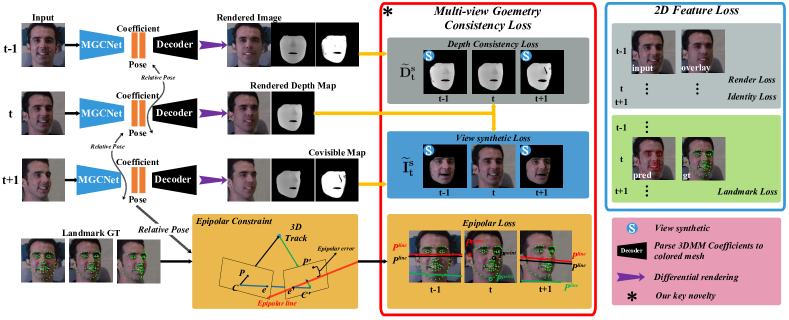
The workflow of MGCNet is shown in Figure 1.
is always considered to be the target of multi-view data.
To simplify the following formulation, we denote all views adjacent to the target view as the source views.
To build up the multi-view consistency in the training process via view synthesis, we first design a covisible map that stores the mask of covisible pixels for each target-source view pair to solve self-occlusion, as the large and extreme face pose cases is common in the real world, and the self-occlusion always happens in such profile face pose cases.
Secondly, we feed the 3DMM coefficients and face poses to the differentiable rendering module [unsuper_genova2018unsupervised], producing the rendered image, depth map, and covisible map for each view.
Thirdly, pixel consistency loss and depth consistency loss are formulated by input images and rendered depth maps in covisible regions, which ensures the consistency of 3DMM parameters in the multi-view training process.
Finally, we introduce the facial epipolar loss, which formulates the epipolar error of 2D facial landmarks via the relative pose of two views,
as facial landmarks is robust to illumination changes, scale ambiguity, and calibration errors.
With these multi-view supervised losses, we are able to achieve accurate 3D face reconstruction and face alignment result on multiple datasets [dataset_aflw20003D_300WLP_zhu2016face, dataset_florence, dataset_bu3dfe_yin20063d, dataset_bu4dfe_yin20063d, dataset_frgc].
We conduct ablation experiments to validate the effectiveness of covisible map and multi-view supervised losses.
To summarize, this paper makes the following main contributions:
-
-
We propose an end-to-end self-supervised architecture MGCNet for face alignment and monocular 3D face reconstruction tasks. To our best knowledge, we are the first to leverage multi-view geometry consistency to mitigate the ambiguity from monocular face pose estimation and depth reconstruction in the training process.
-
-
We build a differentiable covisible map for general view synthesis, which can mitigate the self-occlusion crux of view synthesis. Based on view synthesis, three differentiable multi-view geometry consistency loss functions are proposed as pixel consistency loss, depth consistency loss, and facial epipolar loss.
-
-
Our MGCNet result on the face alignment benchmark [dataset_aflw20003D_300WLP_zhu2016face] shows that we achieve more than a improvement over other state-of-the-art methods, especially in large and extreme face pose cases. Comparison on the challenging 3D Face Reconstruction datasets [dataset_florence, dataset_bu3dfe_yin20063d, dataset_bu4dfe_yin20063d, dataset_frgc] shows that MGCNet outperforms the other methods with the largest margin of .
2 Related work
2.1 Single-view Method
Recent CNN methods [dataset_aflw20003D_300WLP_zhu2016face, super_fit_volu_jackson2017large, super_fit_endtoend_iter_tuan2017regressing, super_fiting_liu2018disentangling, super_fit_tran2018extreme, super_fit_volu_exp_feng2018joint, super_fit_yi2019mmface, unsuper_tran2019towards, super_chen2019photo, super_zeng2019df2net, super_review3_galteri2019deep, super_syn_endtoend_dou2017end, super_syn_guo2018cnn] train the CNN network supervised by 3D face scan ground truth and achieve impressive results. [super_syn_iter_richardson20163d, super_syn_endtoend_dou2017end, super_syn_guo2018cnn] generate synthetic rendered face images with real 3D scans. [super_fit_volu_jackson2017large, super_fit_endtoend_iter_tuan2017regressing, super_fiting_liu2018disentangling, super_fit_tran2018extreme, super_fit_volu_exp_feng2018joint, super_fit_yi2019mmface] propose their deep neural networks trained using fitted 3D shapes by traditional methods as substitute labels. Lack of realistic training data is still a great hindrance.
Recently, some self-supervised or weak-supervised methods are proposed [unsuper_richardson2017learning, unsuper_tewari2017mofa, unsuper_tran2018nonlinear, unsuper_tewari2018self, unsuper_genova2018unsupervised, unsuper_mul_sanyal2019learning_ring, unsuper_tran2019towards, unsuper_yoon2019self, unsuper_zhou2019dense] to solve the lack of high-quality 3D face scans with robust testing result. Tewari et al.[unsuper_tewari2017mofa] propose an differentiable rendering process to build unsupervised face autoencoder based on pixel loss. Genova et al.[unsuper_genova2018unsupervised] train a regression network mainly focus on identity loss that compares the features of the predicted face and the input photograph. Nevertheless, face pose and depth ambiguity originated from only monocular images still a limitation.
2.2 Multi-view or Video Based Method
There are established toolchains of 3D reconstruction [sfm_furukawa2010towards, sfm_wu2011visualsfm, sfm_schoenberger2016sfm, mvs_schoenberger2016mvs], aimming at recovering 3D geometry from multi-view images. One related operation is view synthesis [warp_chen1993view, warp_seitz1996view, warp_fitzgibbon2005image], and the goal is to synthesize the appearance of the scene from novel camera viewpoints.
Several unsupervised approaches [unsuper_mul_ng2019accurate, unsuper_mul_wu2019mvf, unsuper_mul_tewari2019fml, unsuper_mul_sanyal2019learning_ring] are proposed recently to address the 3D face reconstruction from multiple images or videos. Deng et al.[unsuper_mul_ng2019accurate] perform multi-image face reconstruction from different images by shape aggregation. Sanyal et al.[unsuper_mul_sanyal2019learning_ring] take multiple images of the same and different person, then enforce shape consistency between the same subjects and shape inconsistency between the different subjects. Wu et al.[unsuper_mul_wu2019mvf] design an impressive multi-view framework (MVFNet), which is view-consistent by design, and photometric consistency is used to generate consistent texture across views. However, MVFNet is not able to generate results via a single input since it relies on multi-view aggregation during inference. Our MGCNet explicitly exploit multi-view consistency (both geometric and photometric) to constrain the network to produce view-consistent face geometry from a single input, which provides better supervision than 2D information only. Therefore, MGCNet improves the performance of face alignment and 3D face reconstruction as Section 4.
3 Method
3.1 Overview
The inference process of MGCNet takes a single image as input, while in the training process the input is -view images (e.g. for ) of the same face and the corresponding ground-truth 2D landmarks . Then, the MGCNet estimates the 3DMM coefficients and face poses, whose notations are introduced in Section 3.2 in detail. represent the synthesized target images and the depth maps from the source views.
3.2 Model
Face model 3D Morphable Model (3DMM) proposed by [intro_3dmm_blanz1999morphable] is the face prior model of the MGCNet. Specifically, the 3DMM encodes both face shape and texture as
| (1) |
where and denote the mean shape and the mean albedo respectively. , and are the PCA bases of identity, expression and texture. and are corresponding coefficient vectors to be estimated follow [unsuper_mul_ng2019accurate, unsuper_tewari2017mofa, unsuper_tewari2018self]. We use , , and provided by the Basel Face Model (BFM) [intro_3dmm_blanz1999morphable, 3dmm_paysan20093d], and from FaceWarehouse [dataset_cao2013facewarehouse]. We exclude the ear and neck region as [unsuper_mul_ng2019accurate], and our final face model contains vertices.
Camera model The pinhole camera model is employed to define the 3D-2D projection. We assume the camera is calibrated. The face pose is represented by an euler angle rotation and translation . The relative poses from the target view to source views are defined as .
Illumination model To acquire realistic rendered face images, we model the scene illumination by Spherical Harmonics (SH) [sh_ramamoorthi2001efficient, sh_ramamoorthi2001signal] as , where is the normal of the face mesh, is the coefficient. The are SH basis functions and the (B = 3 bands) parameterizes the colored illumination in red, green and blue channels.
Finally, we concatenate all the parameters together into a 257-dimensional vector. All 257 parameters encode the 3DMM coefficients and the face pose, which are abbreviated as coefficient and pose in Figure 1.
3.3 2D Feature Loss
Inspired by recent related works, we leverage preliminary 2D feature loss functions in our framework.
Render loss The render loss aims to minimize the difference between the input face image and the rendered image as , where is the rendered image, is the input image, and M is the number of all 2D pixels in the projected 3D face region. is the skin confidence of pixel as in [unsuper_mul_ng2019accurate]. Render loss mainly contributes to the albedo of 3DMM.
Landmark loss To improve the accuracy of face alignment, we employ the 2D landmark loss which defines the distance between predicted landmarks and ground truth landmarks as where is the number of landmarks, and the projection of the 3D landmarks picked from our face model. It is noted that the landmarks have different levels of importance, denoted as the confidence for each landmark. We set the confidence to 10 only for the nose and inner mouth landmarks, and to 1 else wise.
Identity loss The fidelity of the reconstructed face is an important criterion. We use the identity loss as in [unsuper_genova2018unsupervised], which is the cosine distance between deep features of the input images and rendered images as , where means the element-wise multiplication. and are deep features of input images and rendered images.
Regularization loss To prevent the face shape and texture parameters from diverging, regularization loss of 3DMM is used as where are trade-off parameters for 3DMM coefficients regularization ( by default). are the length of 3DMM parameters , , .
Final 2D feature loss The combined 2D feature loss function is defined as where the trade-off parameters for 2D feature losses are set empirically . We regard the baseline approach in the later experiement as the model trained by only 2D feature losses. In the followings, we present key ingredients of our contributions.
3.4 Occlusion-Aware View Synthesis
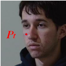
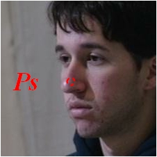
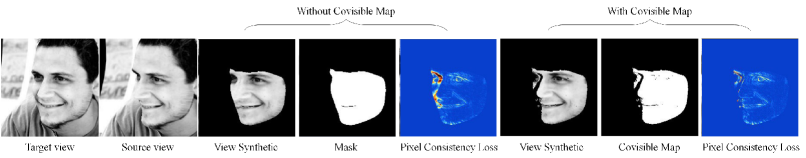
The key of our idea is to enforce multi-view geometry consistency, so as to achieve the self-supervised training. This could be done via view synthesis, which establishes dense pixel correspondences across multi-view input images. However, the view synthesis for face reconstruction is very easily affected by self-occlusion, as large and extreme face pose cases are common in read world applications. As shown in Figure 2, assuming a pixel is visible in the left cheek as shown in Figure 2, the correspondence pixel could not be found in Figure 2 due to nose occlusion. Self-occlusion leads to redundant pixel consistency loss and depth consistency loss. Furthermore the related gradient of self-occlusion pixels will be highly affected by the salient redundant error as red part in Figure 3 (Pixel Consistency Loss subfigure), which makes the training more difficult. For more practical and useful navigation in real scenarios, self-occlusion is worth to solve.
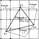
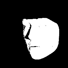
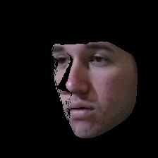
We introduce the covisible maps to account for the self-occlusion. Covisible map is a binary mask indicating the pixels which are visible in both source and target views. During the rendering process of the MGCNet, rasterization builds the correspondence between vertices of a triangle and image pixels , as shown in Figure 2. The common vertices visible in two views (i.e., vertices that contribute to pixel rendering) are called covisible points. Then we define all triangles adjacent to covisible points as covisible triangles. Finally, we project covisible triangles of the 3D face from the target view to image space, as shown in Figure 2, where the white region is covisible region. The improvement brings from covisible maps is elaborated in Figure 3, pixels are not covisible in the left of the nose in target view (red in Figure 3), which result in redundant error. The quantitative improvements are discussed in Section LABEL:sec_abla.
To generate the synthetic target RGB images from source RGB images, we first formulate the pixel correspondences between view pairs . Given a pair correspondence pixel coordinate in , the pixel value is computed by bilinear-sampling [jaderberg2015spatial], and the pixel coordinate is defined as
| (2) |
where represents the equality in the homogeneous coordinates, and are the intrinsics for the input image pairs, is the rendered depth map of the target view, and is the depth for this particular pixel in .
3.5 Pixel Consistency Loss
We generate the synthesized target images by view synthesis, then we minimize the pixel error between the target view and the synthesized target views from the source views as
| (3) |
where represents the synthesized target views from the source views. is the pixel value . Concretely, the first term is the bilinear-sampling operation, which computes the corresponding pixel coordinates using the relative pose and target depth map . is covisible map and denotes the total number of covisible pixels.
3.6 Dense Depth Consistency Loss
Compared to RGB images, depth maps are less adversely affected by the gradient locality issue [bergen1992hierarchical]. Thus, we propose a dense depth consistency loss function which contributes to solving depth ambiguity more explicitly, enforcing the multi-view consistency upon depth maps. Similarly, we synthesize the target depth maps from the source views via bilinear interpolation, and compute the consistency against the target depth map .
One critical issue is that the face region is cropped in the face detection data-preprocessing stage, making the depth value up to scale. To tackle this issue, we compute a ratio of two depth maps and rectify the scale of depth maps. Therefore, we define the dense depth consistency loss as
| (4) |
where are the covisible and depth value. is the depth scale ratio. Our experiment shows that the multi-view geometry supervisory signals significantly improve the accuracy of the 3D face shape.
3.7 Facial epipolar Loss
We use facial landmarks to build the epipolar consistency, as our epipolar loss is based on sparse ground-truth 2D facial landmarks, which is less likely to be affected by radiometric or illumination changes compared to pixel consistency or depth consistency losses, The epipolar loss in the symmetric epipolar distance [hartley2003multiple] form between source and target 2D landmark is defined as
| (5) |
where being the essential matrix computed by , is the matrix representation of the cross product with . We simply omit the subindices for conciseness ( for , for , for ).
3.8 Combined Loss
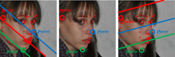
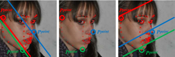
The final loss function for our MGCNet is the combination of 2D feature loss and multi-view geometry loss. Training the network by only 2D feature losses leads to face pose and depth ambiguity, which is reflected in geometry inconsistency as the large epipolar error shown in Figure 4(a). Our MGCNet trained with pixel consistency loss, dense depth consistency, and facial epipolar loss shows remarkable improvement in Figure 4(b), which outstands our novel multi-view geometry consistency based self-supervised training pipeline. Finally, the combined loss function is defined as
| (6) |
where and balance the weights between the 2D feature loss for each view and the multi-view geometry consistency loss. The trade-off parameters to take into account are .
4 Experiment
We evaluate the performance of our MGCNet on the face alignment and 3D face reconstruction tasks which compared with the most recent state-of-the-art methods [unsuper_zhou2019dense, dataset_bulat2017far_lsw3d, super_fit_stn_bhagavatula2017faster, dataset_aflw20003D_300WLP_zhu2016face, unsuper_mul_sanyal2019learning_ring, super_fit_volu_exp_feng2018joint, unsuper_genova2018unsupervised, super_fit_endtoend_iter_tuan2017regressing, unsuper_mul_ng2019accurate, unsuper_tewari2017mofa, unsuper_mul_tewari2019fml, unsuper_tewari2018self] on diverse test datasets including AFLW20003D [dataset_aflw20003D_300WLP_zhu2016face], MICC Florence [dataset_florence], Binghamton University 3D Facial Expression (BU-3DFE) [dataset_bu3dfe_yin20063d, dataset_bu4dfe_yin20063d], and FRGC v2.0 [dataset_frgc].
4.1 Implementation Details
Data 300W-LP [dataset_aflw20003D_300WLP_zhu2016face] has multi-view face images with fitted 3DMM model, the model is widely used as ground truth in [super_fit_endtoend_iter_tuan2017regressing, super_fit_volu_exp_feng2018joint, super_fit_volu_jackson2017large, super_fit_yi2019mmface], such multi-view images provide better supervision than only 2D features. Multi-PIE [dataset_gross2010multi] are introduced to provide multi-view face images that help solve face pose and depth ambiguity. As multi-view face datasets are always captured indoor, and thus cannot provide diversified illumination and background for training, CelebA [dataset_liu2015deep_celeba] and LS3D [dataset_bulat2017far_lsw3d] are used as part of training data, which only contribute to 2D feature losses. Detail data process can be found in the suppl. material.
Network We use the ResNet50 [he2016deep] network as the backbone of our MGCNet, we only convert the last fully-connected layer to 257 neurons to match the dimension of 3DMM coefficients. The pre-trained model from ImageNet [russakovsky2015imagenet] is used as an initialization. We only use views in practice, as views lead to a large pose gap between the first view and the last view. We implement our approach by Tensorflow [abadi2016tensorflow]. The training process is based on Adam optimizer [kingma2014adam] with a batch size of 5. The learning rate is set to , and there are 400K total iterations for the whole training process.
4.2 Qualitative Result
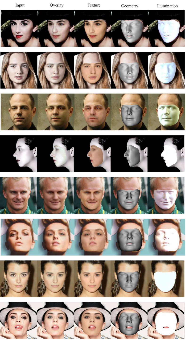
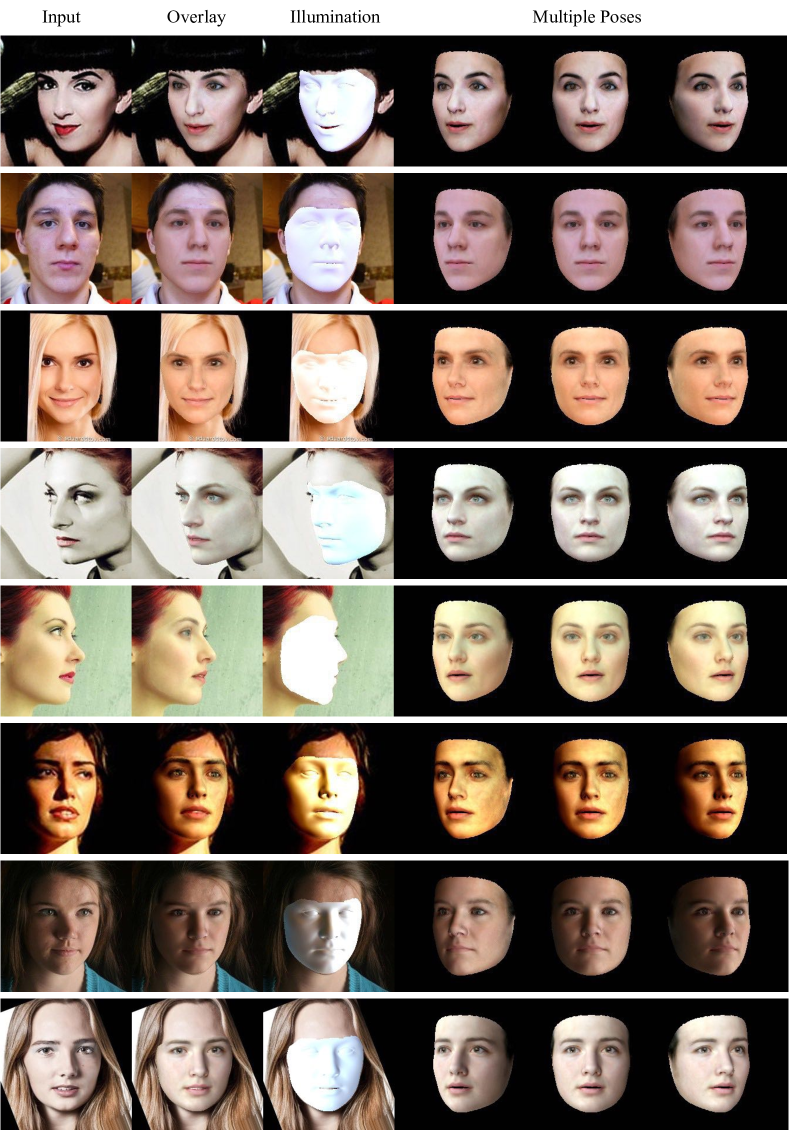
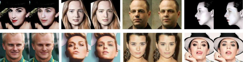
Result in different situations Our MGCNet allows for high-quality reconstruction of facial geometry, reflectance and incident illumination as Figure 5, under full range of lighting, pose, and expressions situations.
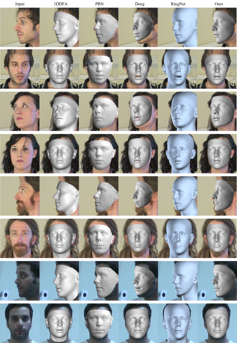
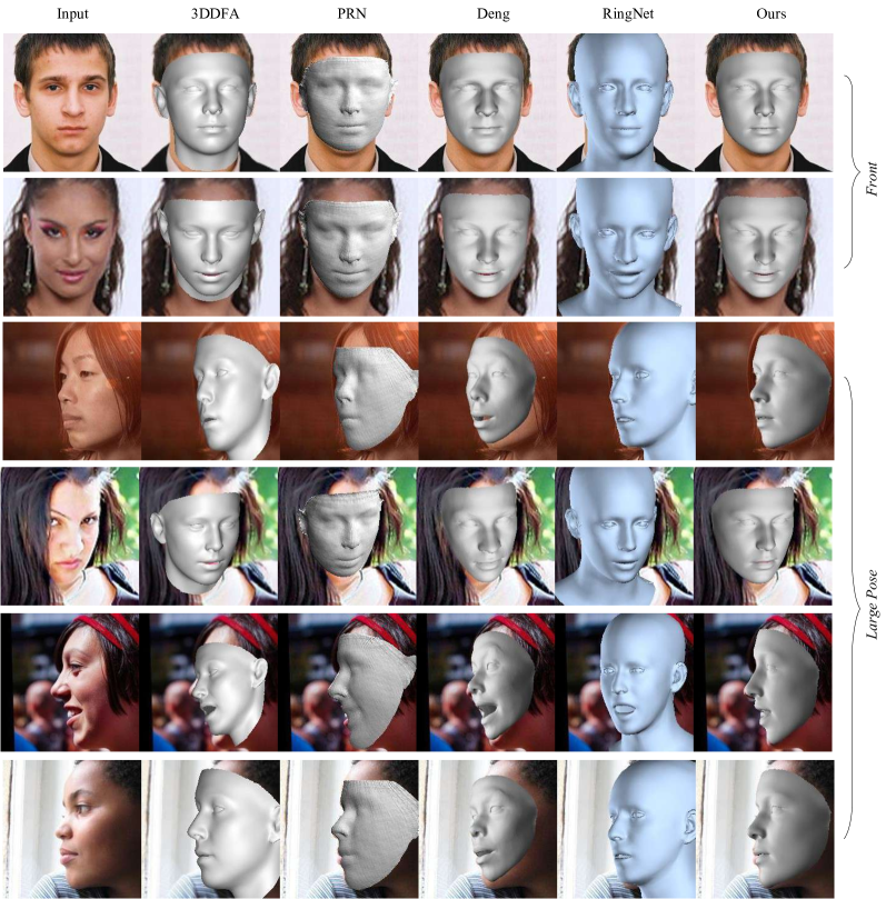
Geometry We evaluate the qualitative results of our MGCNet on AFLW20003D [dataset_aflw20003D_300WLP_zhu2016face]. First, we compare our MGCNet with 3DDFA [dataset_aflw20003D_300WLP_zhu2016face], RingNet [unsuper_mul_sanyal2019learning_ring], PRN [super_fit_volu_exp_feng2018joint], and Deng et al.[unsuper_mul_ng2019accurate] on front view samples, as Row 1 and Row 2 in Figure 6. Our predicted 3DMM coefficients produce more accurate results than the most methods, and we get comparable results with Deng et al.[unsuper_mul_ng2019accurate].
For these large and extreme pose cases as Row 3-6 in Figure 6, our MGCNet has better face alignment and face geometry than other methods. We have more vivid emotion in Row 4 of Figure 6, and the mouths of our result in Row 3,5 have obviously better shape than 3DDFA [dataset_aflw20003D_300WLP_zhu2016face], RingNet [unsuper_mul_sanyal2019learning_ring], PRN [super_fit_volu_exp_feng2018joint], and Deng et al.[unsuper_mul_ng2019accurate]. Besides, the face alignment results from Row 3 to Row 6 support that we achieve better face pose estimation, especially in large and extreme pose cases.
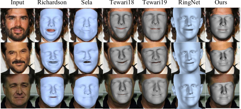
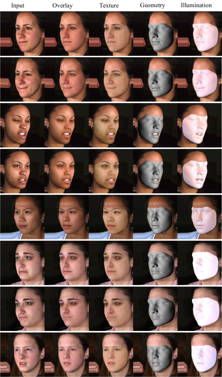
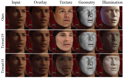
Texture, illumination shadings We also visualize our result under geometry, texture, illumination shadings, and notice that our approach performs better than Tewari18 et al.[unsuper_tewari2018self] and Tewari19 et al.[unsuper_mul_tewari2019fml], where the overlay result is very similar to the input image as Figure 7. Further result and analysis about the result can be found in the suppl. material.
MGCNet does not focus on the appearance of 3DMM as [unsuper_tewari2018self, unsuper_mul_tewari2019fml, unsuper_tran2019towards, super_chen2019photo, super_zeng2019df2net, super_review3_galteri2019deep, super_fit_tran2018extreme, super_iter_sela2017unrestricted], which is only constrained by render loss. However, our multi-view geometry supervision can help render loss maximize the potential during training by accurate face alignment and depth value estimation. This makes MGCNet able to handle 3DMM texture and illumination robustly.
| \hlineB3 Method | 0 to 30 | 30 to 60 | 60 to 90 | Mean | ||||
| \hlineB3 3DDFA [dataset_aflw20003D_300WLP_zhu2016face] | 3.78 | 4.54 | 7.93 | 5.42 | ||||
| 3D-FAN [dataset_bulat2017far_lsw3d] | 3.61 | 4.34 | 6.87 | 4.94 | ||||
| 3DSTN [super_fit_stn_bhagavatula2017faster] | 3.15 | 4.33 | 5.98 | 4.49 | ||||
| CMD [unsuper_zhou2019dense] | - | - | - | 3.98 | ||||
| PRN [super_fit_volu_exp_feng2018joint] | 2.75 | 3.55 | 5.11 | 3.62 | ||||
| \hlineB3 Ours+BL | 2.75 | 3.28 | 4.31 | 3.45 | ||||
| Ours+MGCNet | 2.72 | 3.12 | 3.76 | 3.20 | ||||
| \hlineB3 | ||||||||
| \hlineB3 Method | Cooperative | Indoor | Outdoor | |||
| \hlineB3 Zhu et al.[dataset_aflw20003D_300WLP_zhu2016face] | 2.69 0.64 | 2.23 0.49 | 2.22 0.56 | |||
| Sanyal et al.[unsuper_mul_sanyal2019learning_ring] | 2.33 0.43 | 2.19 0.43 | 2.07 0.45 | |||
| Feng et al.[super_fit_volu_exp_feng2018joint] | 2.30 0.54 | 2.02 0.50 | 2.10 0.60 | |||
| Tran et al.[super_fit_endtoend_iter_tuan2017regressing] | 2.00 0.55 | 2.05 0.51 | 1.95 0.51 | |||
| Genova et al.[unsuper_genova2018unsupervised] | 1.87 0.61 | 1.86 0.60 | 1.87 0.57 | |||
| Deng et al.[unsuper_mul_ng2019accurate] | 1.83 0.59 | 1.78 0.53 | 1.78 0.59 | |||
| Ours | 1.73 0.48 | 1.78 0.47 | 1.75 0.47 | |||
| \hlineB3 | ||||||
4.3 2D Face Alignment
The quantitative comparison of 6Dof pose is not conducted due to different camera intrinsic assumptions of different methods. Therefore, to validate that our MGCNet can mitigate the ambiguity of monocular face pose estimation, we evaluate our method on AFLW2000-3D, and compare our result with Zhu et al.[dataset_aflw20003D_300WLP_zhu2016face] (3DDFA), Bulat and Tzimiropoulos [dataset_bulat2017far_lsw3d] (3D-FAN), Bhagavatula et al.[super_fit_stn_bhagavatula2017faster] (3DSTN), Zhou et al.[unsuper_zhou2019dense] (CMD), and Feng et al.[super_fit_volu_exp_feng2018joint] (PRN). Normalized mean error (NME) is used as the evaluation metric, and the bounding box size of ground truth landmarks is deemed as the normalization factor. As shown in Table 1(a) Column 5, our result outperforms the best method with a large margin of improvement. Qualitative results can be found in the suppl. material.
Learning face pose from 2D features of monocular images leads to face pose ambiguity, the results of large and extreme face pose test samples suffer from this heavily. As the supervision of large and extreme face pose case is even less, which is not enough for training monocular face pose regressor. Our MGCNet provides further robust and dense supervision by multi-view geometry for face alignment in both frontal and profile face pose situations. The comparison in Table 1(a) corroborates our point that the compared methods [dataset_aflw20003D_300WLP_zhu2016face, dataset_bulat2017far_lsw3d, super_fit_stn_bhagavatula2017faster, unsuper_zhou2019dense, super_fit_volu_exp_feng2018joint] obviously degrades when the yaw angles increase from to in Column 4 of Table 1(a). We also conduct an ablation study that our MGCNet outperforms the baseline, especially on large and extreme pose case.
4.4 3D Face Reconstruction
MICC Florence with Video MICC Florence provides videos of each subject in cooperative, indoor and outdoor scenarios. For a fair comparison with Genova et al.[unsuper_genova2018unsupervised], Trans et al.[super_fit_endtoend_iter_tuan2017regressing] and Deng et al.[unsuper_mul_ng2019accurate], we calculate error with the average shape for each video in different scenarios. Following [unsuper_genova2018unsupervised], we crop the ground truth mesh to 95mm around the nose tip and run iterative closest point (ICP) algorithm for rigid alignment. The results of [super_fit_endtoend_iter_tuan2017regressing] only contain part of the forehead region. For a fair comparison, we process the ground-truth meshes similarly. We use the point-to-plane root mean squared error(RMSE) as the evaluation metric. We compare with the methods of Zhu et al.[dataset_aflw20003D_300WLP_zhu2016face] (3DDFA), Sanyal et al.[unsuper_mul_sanyal2019learning_ring] (RingNet), Feng et al.[super_fit_volu_exp_feng2018joint] (PRN), Genova et al.[unsuper_genova2018unsupervised], Trans et al.[super_fit_endtoend_iter_tuan2017regressing] and Deng et al.[unsuper_mul_ng2019accurate]. Table 1(b) shows that our method outperforms state-of-the-art methods [dataset_aflw20003D_300WLP_zhu2016face, unsuper_mul_sanyal2019learning_ring, super_fit_volu_exp_feng2018joint, unsuper_genova2018unsupervised, super_fit_endtoend_iter_tuan2017regressing, unsuper_mul_ng2019accurate] on all three scenarios.
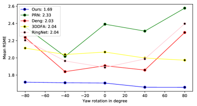
MICC Florence with Rendered Images Several current methods [unsuper_mul_ng2019accurate, super_fit_yi2019mmface, super_fit_volu_exp_feng2018joint, super_fit_volu_jackson2017large] also generate rendered images as test input. Following [unsuper_mul_ng2019accurate, super_fit_yi2019mmface, super_fit_volu_exp_feng2018joint, super_fit_volu_jackson2017large], we render face images of each subject with 20 poses: a pitch of -15, 20 and 25 degrees, yaw angles of -80, -60, 0, 60 and 80 degrees, and 5 random poses. We use the point-to-plane RMSE as the evaluation metric, and we process the ground truth mesh as above. Figure 7 shows that our method achieves a significant improvement of higher than the state-of-the-art methods.
The plot also shows that our MGCNet performs obvious improvement on the extreme pose setting in Figure 7. As we mitigate both pose and depth ambiguity by multi-view geometry consistency in the training process. Extreme pose sample benefits from this more significantly, since the extreme pose input images have even less 2D features. Profile face case contains more pronounced depth info (eg. bridge of the nose), where large error happen.
FRGC v2.0 Dataset FRGC v2.0 is a large-scale benchmark includes 4007 scans. We random pick 1335 scans as test samples, then we crop the ground truth mesh to 95mm around the nose tip. We first use 3D landmark as correspondence to align the predict and ground truth result, then ICP algorithm is used as fine alignment. Finally, point-to-point mean average error (MAE) is used as the evaluation metric. We compare with the methods of Galteri et al.[super_review3_galteri2019deep] (D3R), 3DDFA [dataset_aflw20003D_300WLP_zhu2016face], RingNet [unsuper_mul_sanyal2019learning_ring], PRN [super_fit_volu_exp_feng2018joint], and Deng et al.[unsuper_mul_ng2019accurate]. Table LABEL:tab:frgc shows that our method outperforms these state-of-the-art methods. Our MGCNet performs higher fidelity and accurate result on both frontal and profile face pose view.
”Self-Supervised Monocular 3D Face Reconstruction by Occlusion-Aware Multi-view Geometry Consistency”
Jiaxiang Shang Tianwei Shen Shiwei li Lei Zhou Mingmin Zhen Tian Fang Long Quan
7 Overview
This supplementary document provides detailed evaluation results that are supplementary to the main paper. We propose a self-supervised Multi-view Geometry Consistency based 3D Face Reconstruction framework (MGCNet), which helps mitigate the monocular face pose and depth ambiguity. Firstly, we propose the detailed data pre-process pipeline in Section 8, then we introduce the quantitative evaluation datasets in Section 9. Secondly, we introduce the morphable model and highlight that our MGCNet is a general framework in Section 10. Thirdly, we evaluate the quantitative result by render error between the input image and rendered image in Section 11.1 and we show the qualitative ablation study in Section 11.2. Furthermore, we show further comparison with Tewari19 [unsuper_mul_tewari2019fml] under geometry, texture and lighting in Section 11.3, then we conduct further comparison with some methods on the in the wild images in Section 11.4. Finally, we demonstrate the qualitative comparisons against other methods on MICC Florence dataset [dataset_florence] in Section 11.5 and we also demonstrate some results from AFLW20003D [dataset_aflw20003D_300WLP_zhu2016face] in Section 11.6, which further certify our MGCNet performs accurate result on face alignment task. Then we show the qualitative result on BU-3DFE dataset [dataset_bu3dfe_yin20063d, dataset_bu4dfe_yin20063d] in Section 11.7.
8 Data Preprocess
The images are automatically annotated by the 2D landmark detection method in [dataset_bulat2017far_lsw3d] and the face detection method in [zhang2017s3fd]. We filter the face pose, face attribution, low-resolution images, and blurred images and obtain 390K face images from the above four datasets as our training set. The images are scaled to a resolution of 224 224.
The multi-view images of the training dataset are captured with a consistent lighting condition across views. Theoretically, the photometric consistency will be violated if the lighting across views is dramatically different. Our MGCNet shares the same property with multi-view stereo methods that require overlap across views, this also the reason that we only use views in practice.
9 Quantitative Evaluation Dataset
AFLW20003D is constructed to evaluate face alignment on challenging in the wild images. This database contains the first 2000 images from AFLW [dataset_alfw] with landmarks annotations. We use this database to evaluate the performance of our method on face alignment tasks [dataset_aflw20003D_300WLP_zhu2016face].
MICC Florence is a 3D face dataset that contains 53 faces with their ground truth High-resolution 3D scans of human faces are acquired from a structured-light scanning system from each subject with several video sequences of varying resolution, conditions and zoom level [dataset_florence].
FRGC v2.0 includes 4007 scans of 466 individuals acquired with the frontal view from the shoulder level, with very tiny pose variations. About of the faces have neutral expression, while the others show spontaneous expressions of disgust, happiness, sadness, and surprise [dataset_frgc]. Scans are given as matrices of 3D points of size , with a binary mask indicating the valid points of the face (about 40 K on average).
BU-3DFE BU-3DFE database includes 100 subjects with 2500 facial expression models. The database presently contains 100 subjects (56 female, 44 male), ranging age from 18 years to 70 years old, with a variety of ethnic/racial ancestries, including White, Black, East-Asian, Middle-east Asian, Indian, and Hispanic Latino. Each subject performed seven expressions in front of the 3D face scanner. With the exception of the neutral expression, each of the six prototypic expressions (happiness, disgust, fear, angry, surprise and sadness) includes four levels of intensity [dataset_bu3dfe_yin20063d, dataset_bu4dfe_yin20063d].
10 3D Morphable Model
Blanz and Vetter [intro_3dmm_blanz1999morphable] introduce the 3D morphable model (3DMM). 3DMM benefits the 3D face reconstruction by constraining the solution space, thereby simplifying the problem. In this paper, our goal is to estimate 3DMM parameters from a single photograph.
We conduct our experiments with 3DMM model since it is still a general method that widely used by single-image based latest methods (as in works of [unsuper_zhou2019dense, dataset_aflw20003D_300WLP_zhu2016face, unsuper_genova2018unsupervised, super_fit_endtoend_iter_tuan2017regressing, unsuper_mul_ng2019accurate, unsuper_tewari2017mofa]), and we have proved the superiority of our method over theirs under a fair comparison, as shown qualitatively in the main paper as well as our quantitative result.
As we have clarified in the main paper, our method is focused on improving single-view reconstruction quality via multi-view consistency, our proposed framework is general and is not limited to any specific face model. We believe other face models with better representation ability [unsuper_mul_sanyal2019learning_ring, unsuper_mul_tewari2019fml, unsuper_tewari2018self, unsuper_tran2018nonlinear, unsuper_tran2019towards] can easily plug into our proposed MGCNet.
11 Further Evaluation Result
11.1 CelebA Dataset
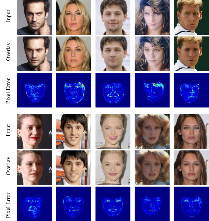
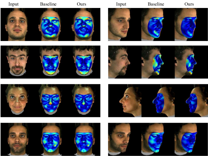
We evaluate the photometric error of our approach by heat maps on the CelebA dataset [dataset_liu2015deep_celeba] as shown in Figure 8 that these images are only used for testing and visualization. We achieve low pixel error, which benefits from using multi-view geometry consistency. This also demonstrates better reconstruction capabilities of our MGCNet to in-the-wild images.
11.2 Alation Study
To evaluate the effects of multi-view geometry consistency losses on the quality of the reconstructed meshes. We conduct ablation studies on the MICC Florence 3D Face dataset [dataset_florence], as shown in Figure 9. We calculate the point-to-plane root mean squared error, and normalize the error to a heatmap. This heatmap indicate that the major improvements regions are jaw, nose and cheekbones region in frontal case, and eye contour, nose, cheekbones regions for the large-pose case. Face geometry (especially in large pose cases), as well as better 3D pose estimation results, are the major improvements bring by our method, thanks to our multi-view geometry constraints that explicitly regularizes the geometry across different views.
11.3 Texture, illumination shadings
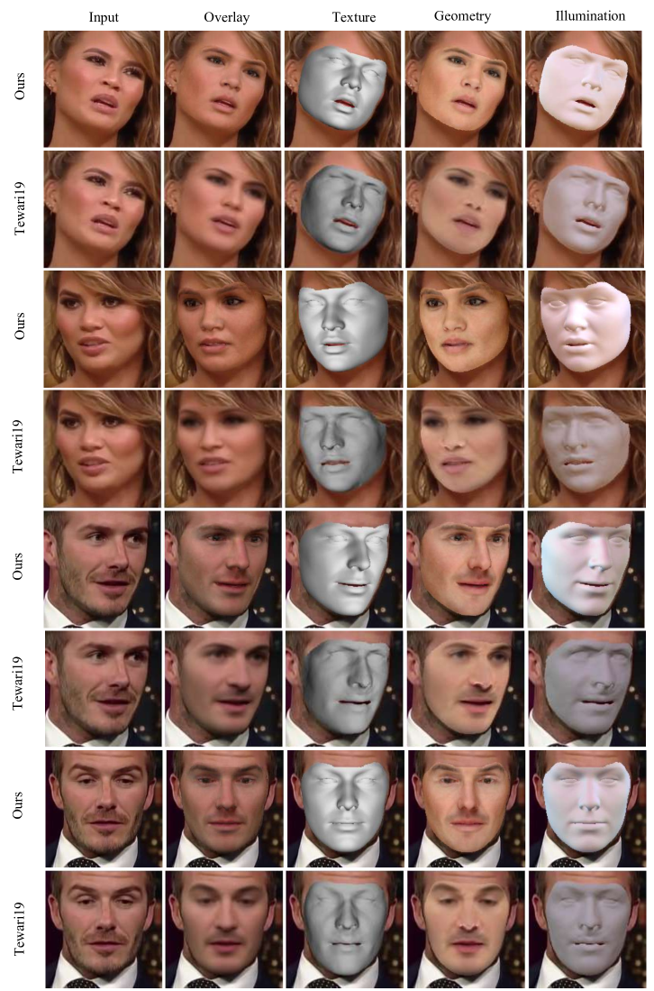
We compare our MGCNet with Tewari19 [unsuper_mul_tewari2019fml] as Figure 10. The result of Tewari19 [unsuper_mul_tewari2019fml] results of geometry are “visually more detail” since they use a face representation more complicated than 3DMM used by our method. However, it is hard to say Tewari19 [unsuper_mul_tewari2019fml] has better geometry results since our method does have a better quantitative result shown in the main paper. The texture model used in Tewari19 [unsuper_mul_tewari2019fml] is also different from 3DMM. Despite that, better geometry generated by our method leads to better texture via the render loss used, which can also support the validity of our MGCNet. As our method is focused on improving the reconstruction quality via multi-view consistency. Our MGCNet is a general system that is not limited to any specific face model.
11.4 In the wild data
Secondly, we visualize our result under geometry overlay situation compared with Richardson et al.[unsuper_richardson2017learning], Sela et al.[super_iter_sela2017unrestricted], Tewari17 et al.[unsuper_tewari2017mofa], Tewari19 et al.[unsuper_mul_tewari2019fml] and RingNet et al.[unsuper_mul_sanyal2019learning_ring], and we notice that our approach performs better than methods [unsuper_richardson2017learning, super_iter_sela2017unrestricted, unsuper_tewari2017mofa, unsuper_mul_tewari2019fml, unsuper_mul_sanyal2019learning_ring] as shown in Figure 12.
We also show some detail intermediate result about Figure 5 in the main paper in Figure 14.
11.5 MICC Florence Dataset
Firstly, we compare our MGCNet with Zhu et al.[dataset_aflw20003D_300WLP_zhu2016face] (3DDFA), Sanyal et al.[unsuper_mul_sanyal2019learning_ring] (RingNet), Feng et al.[super_fit_volu_exp_feng2018joint] (PRN), and Deng et al.[unsuper_mul_ng2019accurate]. For each sample in MICC Florence, we pick both front face images and large face pose images as test data. We show the geometry overlay of the reconstruction result, which we achieve more accurate results than the most methods, and we get better results than Deng et al.[unsuper_mul_ng2019accurate] in the large pose case as Figure 11.
11.6 AFLW20003D Dataset
AFLW20003D is constructed by [dataset_aflw20003D_300WLP_zhu2016face] to evaluate face alignment. Since the images are captured in the wild and show large variations in pose and appearance, which is a challenging 3D face alignment dataset. We use this database to evaluate the performance of our method on face alignment tasks.
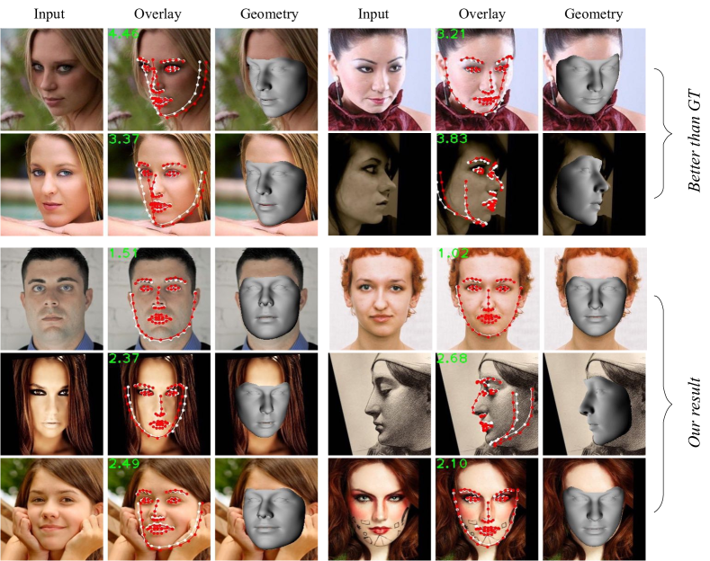
As a supplementary to the quantitative evaluation in the main paper, we first demonstrate some results even better than the ground truth from AFLW20003D [dataset_aflw20003D_300WLP_zhu2016face] in Figure 13. Besides, we also show our result that performs accurate face alignment results, where red lines are predicted landmarks by our method, white lines are ground truth from [dataset_aflw20003D_300WLP_zhu2016face].
Furthermore, we visual our MGCNet result from multiple viewpoints in Figure 15 on AFLW20003D [dataset_aflw20003D_300WLP_zhu2016face], which shows that we get vivid reconstruction results.
11.7 BU-3DFE Dataset
We present more qualitative reconstruction results of our MGCNet on BU-3DFE dataset [dataset_bu3dfe_yin20063d, dataset_bu4dfe_yin20063d]. In Figure 16, we show six samples with various expressions, the reconstructed 3D face showed with face pose, texture, geometry and illumination. This quantitative evaluation of our geometry reconstruction on the BU-3DFE dataset [dataset_bu3dfe_yin20063d, dataset_bu4dfe_yin20063d] shows that our MGCNet can even handle different expression situation. For the prediction of albedo and lighting, while the texture quality would be benefited from better geometry implicitly via the render loss, the ambiguity in illumination and face albedo is an intrinsic issue due to the problem’s nature, and our SH lighting is RGB-channel, limit the SH lighting to one channel will help.