Air-to-Ground Channel Characterization for Low-Height UAVs in Realistic Network Deployments
Abstract
Due to the decrease in cost, size and weight, Unmanned Aerial Vehicles are becoming more and more popular for general-purpose civil and commercial applications. Provision of communication services to UAVs both for user data and control messaging by using off-the-shelf terrestrial cellular deployments introduces several technical challenges. In this paper, an approach to the air-to-ground channel characterization for low-height UAVs based on an extensive measurement campaign is proposed, giving special attention to the comparison of the results when a typical directional antenna for network deployments is used and when a quasi-omnidirectional one is considered. Channel characteristics like path loss, shadow fading, root mean square delay and Doppler frequency spreads and the K-factor are statistically characterized for different suburban scenarios.
Index Terms:
UAV; Air-to-Ground; Communications channels; Time-varying channels; Aircraft communicationI Introduction
Small UAVs are rapidly changing their main scope from the traditional military usage in hostile environments [1, 2] to general-purpose civil and commercial applications. The decrease in their cost, size and weight, the increase of their battery life, their high maneuverability and their ability to hover [3] make them an appropriate tool for a wide set of applications, such as border surveillance, operations in inaccessible areas, delivery of goods, search and rescue missions [3, 4, 5, 6], precise land mapping by aerial imagery [7, 8, 9, 10] or precise farming [11, 12]. The provision of temporary network access after natural disasters, emergency situations or in saturated environments became one of the key scenarios addressed by the fifth generation (5G) communication systems [1, 13] due to the ability of the UAVs for fast deployments [14, 15, 16, 17, 18, 19].
Regardless of the application under consideration, UAV communications can be classified into two types:
-
•
Payload-oriented communications: used to transmit non-critical user data, in general they seek to maximize the data rate in a best-effort manner, being tolerant to errors or delays. This could be the case e.g. of transmitting the video signal from the on-board cameras in digital imagery.
-
•
Critical communications: they involve safety and control-related messages and usually imply low data rate requirements, but very high Quality of Service (QoS) standards in terms of delay and availability. Although in many cases UAVs could fly autonomously, it may be required to reliably change some settings during operation for safety purposes. This is one prerequisite for UAV traffic management, an area under exploration by the Federal Aviation Administration (FAA) and the National Aeronautics and Space Administration (NASA) [20, 21].
The use of ground Long Term Evolution (LTE) or future 5G deployments to provide network access to UAVs devoted a great level of interest by the research community. In fact, the 3rd Generation Partnership Project (3GPP) approved the corresponding study and work items [22, 23] to investigate the feasibility of serving UAVs by terrestrial LTE deployments [24]. However, the use of a terrestrial deployment for the provision of network access to UAVs proposes a set of major signal propagation challenges regarding coverage and interference management. In these deployments the antennas are focused on serving users at ground level and thus they are down-tilted. This way, the ground itself, as well as the terrestrial elements such as buildings, define the geometric area for each cell and limit its interference in the neighboring cells. In the case of UAVs, for public-safety reasons, most of the countries limit the applications to low altitude flights (below m) under Visual Line-of-Sight (VLoS) conditions [25, 26, 24]. On the one side, the down-tilted configuration of the Base Station (BS) antennas is not optimum for serving UAVs, even for low-height applications. On the other side, even if the configuration of the BS antennas was adapted to provide sky coverage, the strategies for management of the inter-cell interference would probably need to be reviewed, since the propagation is naturally more line-of-sight (LoS)-like [27] and no obstacles would help to limit each cell, differently from the terrestrial case [28]. Moreover, this would be also true for the uplink communications (i.e., those from the UAV to the BS), since the area of interference of an UAV would be less limited by the ground elements and probably affect both to the neighboring cells as well as to other potential nearby UAVs, hence impacting both terrestrial and aerial users [20]. Indeed, the interference is one of the main focus of the 3GPP study item on enhanced LTE support for aerial vehicles [24, 20, 29]. More challenges from the propagation point of view arise from the influence of the UAV structure itself in the shadowing characteristics [30] or due to the fact that, since the flights are performed at low altitudes, the ground environment has non-negligible effects on the communications channel. Due to the propagation challenges mentioned, the accurate study of the Air-to-Ground (A2G) communications channel for low-height UAVs from a propagation point of view becomes essential. An accurate statistical characterization of the communications channel between a BS and an UAV is the first step to effectively evaluate different strategies for interference mitigation or network deployments in complex environments consisting of several BSs –with either directional/sectorial or omnidirectional radiation patterns– and users by using tools such as system-level simulators.
I-A Related Work
Different approaches to the characterization of the A2G communications channel for UAVs are proposed in the literature, based on simulations and/or measurements. In the next paragraphs the main related works are analyzed.
I-A1 A2G Channel Characterization by Simulations
In [20], the authors propose the use of the 3GPP channel models in [31] for UAVs at altitudes below the base station antenna height and free-space propagation for higher cases. In [32] new statistical models for A2G channels in the range of frequencies between MHz and GHz and urban environments are provided. In [33] the influence of the elevation angle on the path loss and shadowing are evaluated from the simulated propagation data extracted from a three-dimensional outdoor deterministic ray-tracing model. Ray-tracing is also used in [34] to characterize mmWave propagation ( GHz and GHz) for urban, suburban, rural and over sea environments.
I-A2 A2G Channel Characterization by Measurements
Several works focused on the characterization of the path loss for the A2G channel for UAVs. In [35], the authors obtain the aerial path loss as an excess value to the path loss that would correspond to a terrestrial user for a LTE cellular deployment in the band of MHz in typical suburban environments. Flight heights between m and m were considered. In [36], modeling of the path loss exponents for the A2G link in open field and campus scenarios is considered. Height values between m and m at m ground distance between the transmitter and the receiver are considered. The effect of the UAV orientation is also studied.
In [26], the shadowing is also characterized, along with the path loss. The authors consider the radio channel between UAVs and commercial LTE BSs at the MHz band, link distances between km and km, and flight heights between m and m. In [37], statistical models to characterize not only the large-scale fading but also the small-scale fading and multipath propagation are proposed. The work is based on a Ultra Wide-Band (UWB) measurement campaign in the frequency range between GHz and GHz on several scenarios including blockage of the on-ground receiver by foliage or not and with very low flight heights between m and m. The multipath propagation is characterized by means of the the power delay profile (PDP) and the root mean square (RMS) delay spread.
In [38], a height and distance-aware aerial radio channel model is derived from measurements taken with a helium balloon in stationary positions at heights up to m. The ground distance between the base station and the receiver is m. The tests are performed by passive sounding of Global System for Mobile Communications (GSM) and Universal Mobile Telecommunications System (UMTS) signals in an urban environment at a center frequency of MHz.
In [39] the variation of the mean angle of arrival (AoA) and Angular Spread (AS) with flight height is evaluated based on experimental measurements in both urban and rural scenarios using commercial LTE deployments. Since the authors consider a large antenna array, they used a crane to lift it to different heights, instead of an actual UAV during the measurements. By using a similar deployment, in [40] the authors study the performance of different multi-antenna receiver techniques for UAV communications.
Probably the richest set of recent measurements regarding A2G channel characterization for non-low UAV flight heights is provided by D. Matolak, et al. in [41, 42, 43, 44, 45, 46, 30, 47, 48, 49, 50], among others. Sections of the L and C bands [51] are considered, with bandwidths of MHz and MHz, respectively. As the ground transmitter, a transportable tower with variable height (from m to m) was considered, whereas a piloted aircraft was used as the receiver, being the flight height values between m and m and the link distances between m to km, approximately. Channel parameters such as path loss, delay spread, stationarity distance, K-factor or inter-band and spatial correlation were evaluated. Characterizations for path loss and Multipath Components were proposed for different environments, such as over-water (see [45, 30]) or over-freshwater (see [49]), hilly and mountainous environments (see [44]), suburban or near-urban scenarios (see [46, 41]), and hilly suburban environments (see [42]). In [52], a geometrical-statistical channel modeling approach for the A2G channel in L-band is considered, whereas the authors show how the channel parameters can be derived from the measurement data in [45, 53]. In the latter work, results from flight trials with an aircraft for characterizing the A2G channel for the L-band in positioning applications are shown, being the considered bandwidth MHz. The work, being an extension of [54] considers PDP, Doppler frequency Delay Profile, mean delay, RMS Doppler frequency spread and RMS delay spread, as well as ranging accuracy results. Different scenarios such as in-route cruise, climb-and-descent and takeoff-and-landing are considered. Flight altitudes range from km to km, except for the takeoff-and landing scenario, which considers heights between m and m. Link distance ranges from m to km.
Based on a extensive measurement campaign using an UAV and a commercial LTE BS in suburban environments, the publications [24, 55, 56] were released. In [24, 55] a stochastic channel model was proposed, including characterizations of path loss, shadow fading, delay spread and Doppler frequency spread for horizontal and vertical flights at different heights and distances to the BS. In [56], a big-data-assisted channel modeling strategy is applied to find the most sensitive channel parameter from a specific set for the A2G UAV channel and to characterize it (the selected parameter was the K-factor). In [57], some of the measurement environments in the current paper are considered to test the accuracy of graph modeling channel simulation techniques to reconstruct the PDP and MPCs of the A2G UAV channel. It is also worth noting that [58] proposes channel emulation in multi-probe anechoic chambers as a feasible alternative to extensive measurement campaigns.
Increasing interest in characterizing multiple-input, multiple-output (MIMO) channels technologies for A2G communications is also appreciated. E.g., in [59], the GAGE channel model proposed in [60], further developed in [61] by means of the measurement results obtained in [62], was extended to the MIMO case. Test measurements of MIMO communications for the A2G channels are reported in [63] ( MIMO) or [64] ( case). In [65], the communications channel between a 8-antennas ground receiver and a two-antennas transmitter low-altitude UAV is studied by means of measurements. Temporal and spatial properties of the channel are studied for flight heights of approximately m, for a carrier frequency of MHz, and a bandwidth of MHz and two different distances between the receiver and the flight route.
I-B Main Contributions
-
•
In this manuscript, a measurement campaign for the A2G low-height UAV communications channel was performed. The measurement campaign systematically studied different suburban environments at different flight height values between m and m. Furthermore, both an omnidirectional antenna as well as typical BS one were considered at the transmitter. While the results for the omnidirectional antenna allow for obtaining an accurate characterization of the channel characteristics, results for the directional BS antenna show the behavior for an individual sector of a BS (note that, in practical deployments, several sectors per BS are set up).
-
•
A High-Resolution Parameter Estimation (HRPE) algorithm was used to estimate the attenuation, delay and Doppler frequency values for the different MPCs exhibited by the channel. Based on those results, the communications channel was statistically characterized in terms of the path loss, shadow fading, RMS delay and Doppler frequency spreads and K-factor. The variation of the mentioned channel characteristics with the flight height, distance between the UAV and the BS, the ground environment and the considered antenna at the BS was systematically studied. The obtained channel characteristics provide valuable insights for the design of UAV communications systems and their applications, as well as for the related network deployments.
The structure of this paper is as follows: Section II describes the measurement environment and setup considered, whereas Section III describes how the acquired samples were processed. Section IV statistically characterizes the channel observed for the different measured environments and transmitter configurations, and Section V contains the main conclusions of the performed study.
II Measurements Environment and Procedure
In this section, a systematic measurement for characterizing the A2G low-height UAV communications channel is detailed. Section II-A defines the considered measurement environments, whereas Section II-B describes the employed measurement setup.
II-A Measurement Environment
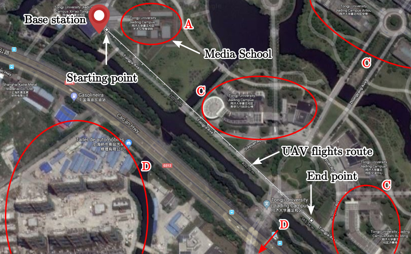
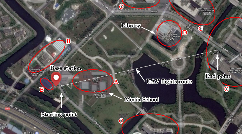
A measurement campaign consisting in horizontal flights at different heights in several suburban scenarios at the Jiading Campus of the Tongji University (Shanghai, China) was performed. Two environments were considered, referred to as Environment I and Environment II, imaged respectively in Figs. 1(a) and 1(b). The figures also show the position of the transmitter111Coordinates of the transmitter expressed as (latitude, longitude) are: ., as well the flying routes along with their starting and end points222Coordinates of the starting point and end point expressed as (latitude, longitude) are: and for the Environment I, respectively; and and for the Environment II route, respectively.. Moreover, buildings with different heights exist in the environment. To approximately describe the building properties, some clusters of buildings are marked in the figures with red ellipses and labeled with the characters from “A” to “D” based on the corresponding approximate building heights, according to the Table I. The so-called Environment I consists of a LoS straight flight along a road without obstacles, being the total length about m. For the Environment II, a m-long straight flight in which the UAV crosses between several buildings is considered, resulting in an Obstructed LoS (OLoS) environment for the lowest height value considered, whereas it can be still categorized as LoS for higher flight heights. More specifically, between the values of m and m (horizontal distance between the UAV and the BS), the UAV flies on top of the Media School building. The height of the building is irregular, but its maximum height point is around m lower than the lowest flight height considered. Between the horizontal distance values m and m the UAV flies close to the library, which is approximately m high. Both mentioned buildings are also marked in Figs. 1(a) and 1(b).
| Cluster label | Range of heights [m] |
|---|---|
| A | |
| B | – |
| C | – |
| D |
For each measurement environment, four horizontal round-trip flights were considered, having a different flight height in the go and the return trip. Table II summarizes the height values considered.
| Flight no. | Height (go trip) [m] | Height (return trip) [m] |
| 1 | 15 | 25 |
| 2 | 35 | 45 |
| 3 | 60 | 75 |
| 4 | 90 | 105 |
II-B Measurement Equipment
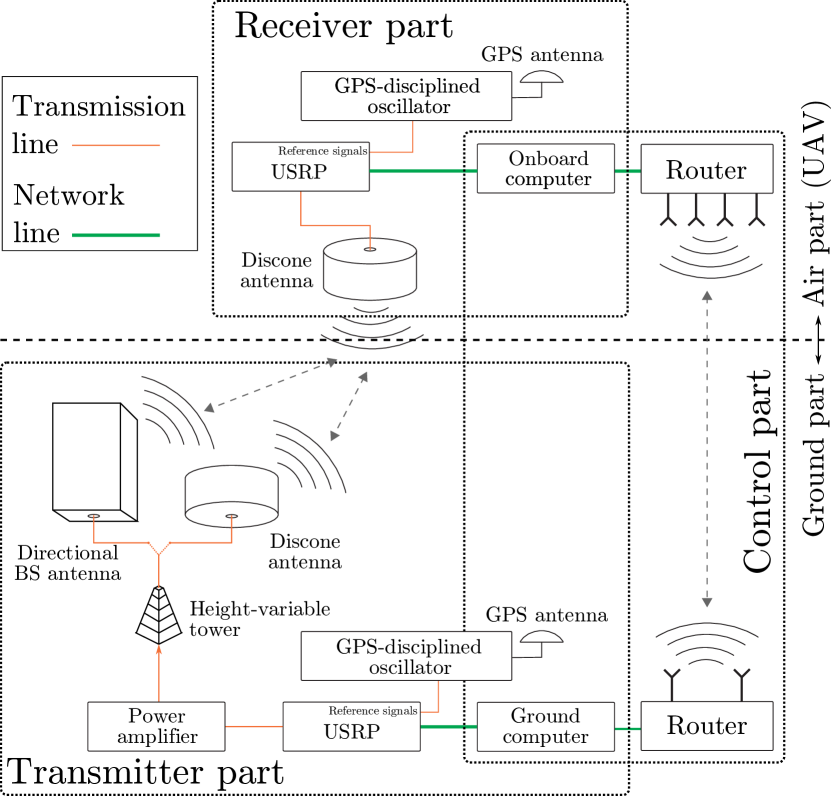
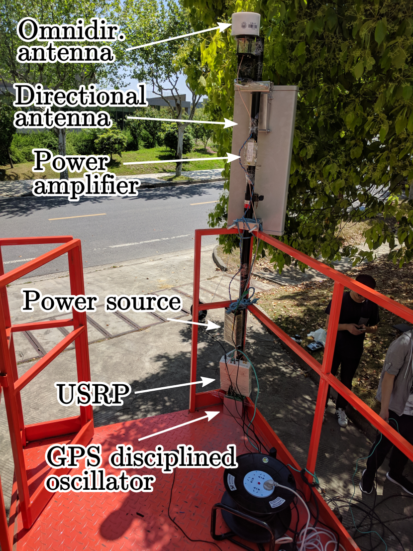
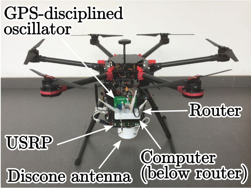
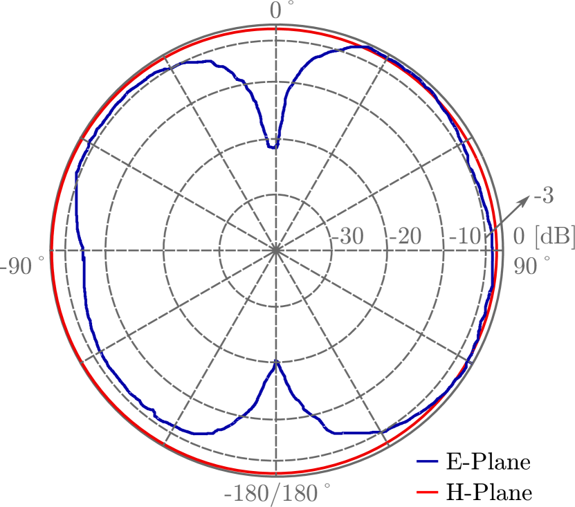
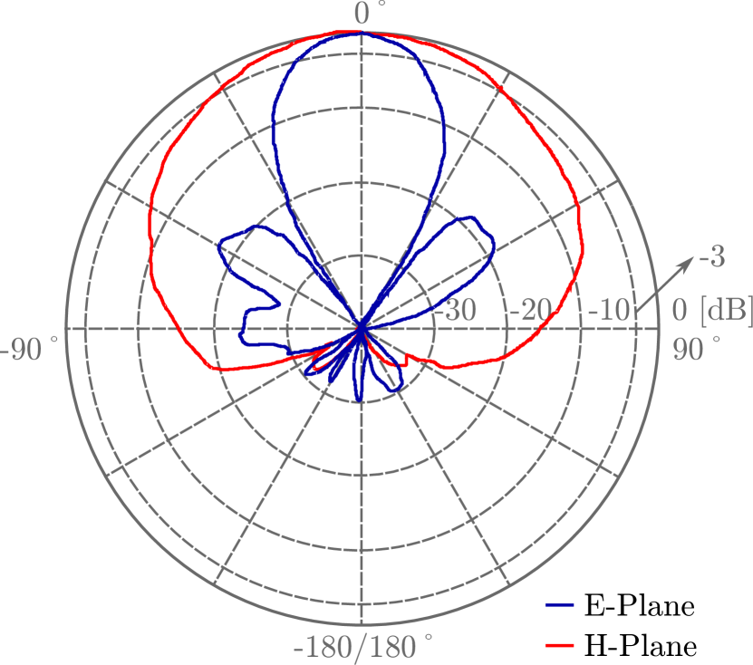
Fig. 2(a) illustrates a diagram of the equipment transmitting and acquiring the signals. It consists of two parts, the air part and the ground part. The air part was loaded on a UAV as illustrated in Fig. 2(c). It contains the following components: a quasi-omnidirectional packaged discone antenna (see the radiation pattern in Fig. 3(a)), a Universal Software Radio Peripheral (USRP) N-210 used to acquire the signals, a Global Positioning System (GPS)-disciplined oscillator that generates accurate MHz as well as Pulse Per Second (PPS) reference signals to be provided to the USRP for synchronization purposes, a small computer base unit that controls the USRP device and stores the received data, and a commercial Wi-Fi router. The ground part contains another USRP N-210 used to transmit the signals, a GPS-disciplined oscillator, a power amplifier and two transmitter antennas, being only one used at a time (see Fig. 2(b)). Note that the MHz and PPS signals at both ends of the channel (transmitter and receiver) enable synchronization of the used USRPs. On the one hand, the MHz is used as a reference for the internal oscillators of the USRPs, hence both transmitter and receiver are synchronized in frequency up to the limits of the hardware used, which is essential for the accuracy of the obtained results. On the other hand, PPS signal enables synchronization of the sample times for the transmitter and the receiver. This way, the transmitter and receiver share a common absolute time-basis. By knowing the time instants in which an orthogonal frequency-division multiplexing (OFDM) frame transmission starts and when it is received, the absolute propagation delay can be estimated. With the aim of helping the research on the feasibility of serving aerial vehicles using LTE network deployments with BS antennas targeting terrestrial coverage, two antennas were considered at the transmitter, being one of them the same model mounted at the receiver and the other a typical BS directional antenna (see Fig. 2(b)), with their respective radiation patterns shown in Figs. 3(a) and 3(b). While the results for the omnidirectional antenna allow for obtaining an accurate characterization of the channel characteristics, results for the directional BS antenna show the behavior for an individual sector of a BS (note that, in practical deployments, several sectors per BS are set up). Both antennas are mounted at a height-variable tower fixed at a height of m. Finally, a laptop is connected to the ground USRP device to act as a transmitter. Furthermore, by using another commercial Wi-Fi router, a local area network is established with the computer on the UAV allowing to control the on-board equipment remotely. This connection is only required to be available when the receiver is at the vicinity of the human operator (close to the transmitter) in order to be able to send respective commands to start and stop the signal acquisition, i.e., no permanent connection is required during the whole flight. The receiver is able to work and acquire samples autonomously after it receives a command to start the signal acquisition until it receives a command to stop the acquisition. Note also that the UAV flies automatically on preprogrammed routes and hence does not need permanent connection to ground. However, a manual operator followed the UAV on ground during the measurements to keep the connection for safety purposes. It is worth noting that the routers worked at the frequency band of GHz causing no interference to the measurements. More specifically, the measurements were performed considering a central carrier frequency of GHz and a bandwidth of MHz (see Section III), values which are similar to those corresponding to commercial LTE deployments in the area of the measurements333Note also that the GHz band is planned to be used in sub- GHz 5G network deployments in China and other countries.. Moreover, the measurements are geo-localized based on the GPS data and the effect of the radiation pattern of the omnidirectional antennas at the UAV and the BS was compensated. However, the effect of the radiation pattern of the directional antenna used at the BS was not removed because we are interested in comparing the results when a directional antenna is considered with those in which the channel is not affected by the antennas (e.g., when an omndirectional antenna is used and its radiation pattern is compensated). The directional antenna is oriented so that the axis of the main lobe follows the direction of the m height flight for each scenario. This way, a tilt configuration was considered, being the main lobe parallel to the ground. Table III details the main parameters of the configuration of the radio equipment used for the measurements.
| Parameter | Value |
|---|---|
| Transmit power | dBm |
| Antenna gain | dBi (omnidirectional, UAV and BS) |
| dBi (directional, BS) | |
| BS antenna height | m |
III Signal Generation and Processing
Both for the generation as well as processing of the signals, the so-called “GTEC 5G Simulator” was used [66, 67]. The “GTEC 5G Simulator” is a versatile piece of software that enables to fully configure the transmit signal and includes all the necessary developments for processing the acquired samples, such as channel estimation, interpolation and equalization algorithms, as well as time and frequency synchronization444The source code of both the GTEC Testbed and the GTEC 5G Simulator is publicly available under the GPLv3 license at https://bitbucket.org/tomas_bolano/gtec_testbed_public.git.. Recently, a HRPE algorithm, namely space-alternating generalized expectation-maximization (SAGE) algorithm, similar to that proposed in [68], was integrated in the “GTEC 5G Simulator” receiver, which allows us to estimate the different parameters of the impinging waves for the acquired signals. More specifically, we consider the delay, the complex-valued amplitude, and the Doppler frequency for each path. For this study, an OFDM signal featuring a sampling rate of MHz was considered. The frame structure is very similar to the one defined for the MHz downlink profile of LTE [69]. Therefore, the estimated time-varying channel impulse response for the th frame is expressed as
| (1) |
where is the time variable, is the delay variable, is the number of waves or paths considered, is the th-path amplitude, and are the respective Doppler frequency and delay for the th path, and is the Dirac delta function. We also consider that for , the th MPC is not necessarily the same, i.e., the situation and may be observed. For our study, we estimated paths, which is a number large enough to capture all the MPCs of the signal in the considered environments. Table IV details the main parameters of the signal generation and processing chains considered.
| Parameter | Value |
|---|---|
| Carrier frequency | GHz |
| Bandwidth | MHz |
| ( MHz without guard band) | |
| Sampling frequency | MSamples/s (upsampled to |
| MSamples/s when transmitting) | |
| FFT size | points |
| Used subcarriers | (excluding DC) |
| Subcarrier spacing | kHz |
| Cyclic prefix length | samples |
| Estimated paths | |
| Delay resolution | ns |
IV Channel Characterization for the Flights
This section shows the results of the statistical channel characterization for both measurement environments and both transmitter antennas considered. For each of the channel characteristics, along with its definition, a sample plot of the obtained results is shown. Unless otherwise specified, the so-called “sample case” corresponds to the omnidirectional antenna and the Environment I, considering all the height values. The channel characteristics are plotted versus the horizontal distance between the UAV and the BS. We provide both a cloud of points with the individual estimated values per frame (see Eq. 1) as well a smoothed curve for the sake of clarity. Finally, only the range of horizontal distances in which the speed of the UAV is stable (approximately from m to m) was considered. After graphically showing the results for the sample case, statistical fittings are proposed for all the combinations of flight heights, measurement environment and transmitter antenna; and a discussion on the obtained results is provided. Note that in some cases, the results for different height values can be well described by a common statistical distribution. This way, in some cases we consider a single statistical distribution for certain flight height range. Furthermore, for the sake of clearness, only some sample empirical cumulative distribution functions, as well as their fittings, are shown in the paper.
Sections IV-A and IV-B consider the path loss and the shadow fading, respectively, whereas Section IV-C considers the PDP and Doppler frequency power spectral density (PSD). Sections IV-D and IV-E consider the RMS delay and Doppler frequency spreads, respectively, and Section IV-F considers the Ricean K-factor.
IV-A Path Loss
The path loss is the ratio between the transmitted and the received power, given by [70] in decibels as
| (2) |
where is the path loss for a distance , is the transmit power, and is the received power at a distance . The path loss can be modeled by a simple log-distance model [70] as
| (3) |
where is the so-called “break distance” (a reference distance relatively close to the transmitter [70]), is the mean path loss at the distance , is the path loss exponent, is a zero-mean Gaussian random variable, and .
Fig. 4(a) shows the relative received power values for the sample case, whereas Fig. 4(b) shows the corresponding linear fit for each of the relative received power clouds, obtained by applying a robust linear fit method [71]. All the obtained path loss exponents are detailed in Table V, for both transmitter antennas as well as for the two environments considered.
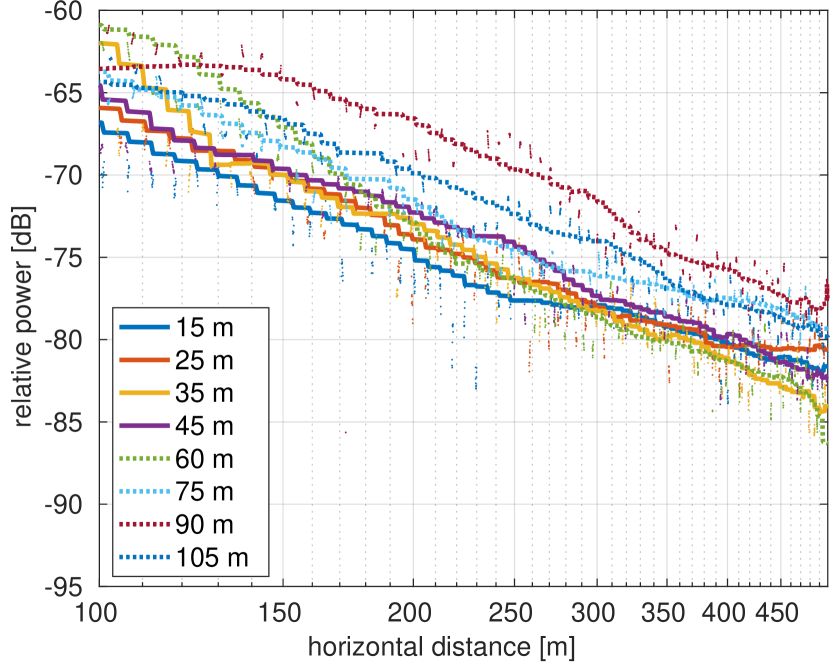
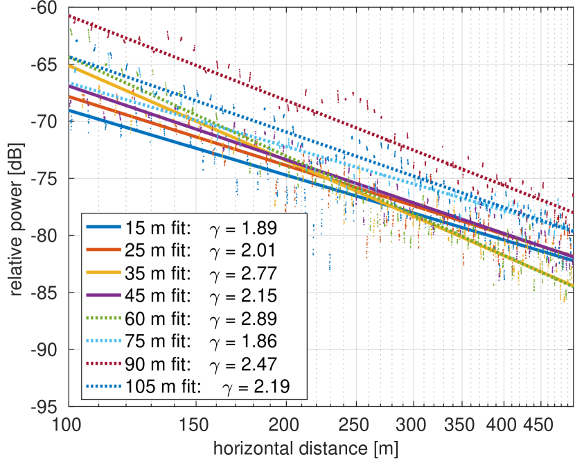
It can be seen that the path loss exponent results are quite dependent with both the height and the environment considered. The transmit antenna has also a great influence on the results. When the omnidirectional antenna is used, the path loss exponent increases with the flight height reaching a maximum at m and then slightly decreases with the height. For the case of the Environment II, two exponents are calculated when the flight height is m, labeled as LoS and OLoS, respectively555Note that there are no OLoS results in the models corresponding to the Environment I since, for this environment, all the flights are performed in LoS conditions.. This is due to the effect of partial blockage of the low-height building overflight by the UAV (see Fig. 1(b)), which intrudes the Fresnel Area. This way, a sharp drop in the receiver power for both the omnidirectional and directional transmit antennas is exhibited after the UAV crosses the building (at around a horizontal distance of m from the BS), impacting severely on the path loss exponent. Hence, the LoS path loss exponent corresponds to the propagation before crossing the building and the OLoS for the rest of the UAV flight route. For the cases when the directional antenna is used, the results are less regular. In general, it can be seen that the path loss exponent is larger for moderate heights (from m to m), and severely decreases for higher flights (those whose heights exceed m), obtaining values lower than (marked with a star in Table V). This is due to the fact that, for moderate values of horizontal distance, the UAV does not fall within the main lobe of the radiation pattern of the directional antenna but still receives eventual contributions from the second lobe (see Fig. 3(b)). When the horizontal distance increases, the UAV can receive contributions from the main lobe of the antenna. Hence, the relative received power is not monotonically decreasing with the horizontal distance to the BS and the log-distance model for the path loss cannot track the instantaneous effect of the combined channel plus antenna radiation pattern for the whole flight. In this case, a model that includes the effect of the BS antenna radiation pattern would be required. However, it must be considered that the absolute received power for these flights is quite low, indicating that a deployment based on terrestrial antennas would need multiple sectors with directional antennas featuring different orientations to be able to cover a large range of flight heights in practice.
| Height | Env. I | Env. I | Env. II | Env. II |
|---|---|---|---|---|
| [m] | Omnidir. ant. | Dir. ant | Omnidir. ant. | Dir. ant |
| (LoS) | ||||
| (OLoS) | – | – | ||
IV-B Shadow Fading
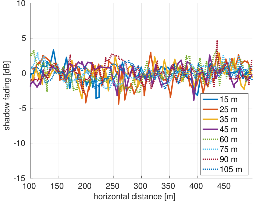
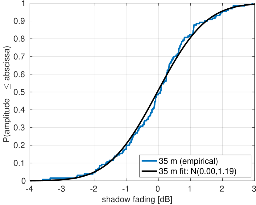
The shadow fading is calculated by subtracting the path loss from the smoothed received power. Fig. 5(a) shows the shadow fading for the sample case. Not clear dependency with the distance to the BS is appreciated in the shadow fading results. Fig. 5(b) shows the corresponding empirical CDF as well as its fitting when the height is . In general, all the shadow fading values can be fit by a normal distribution with zero mean and the variance values specified in Table VI. It can be seen that for the cases in which the omnidirectional antenna is used at the BS the shadow fading tends to decrease with the flight height, since the channel becomes more LoS-alike. For the lowest height values, the shadow fading is slightly increased due to the effects of the ground elements. This effect is also appreciated for the case of the directional antenna. However, then the directional antenna is used, the shadow fading is not decreased with the flight height. This is caused by the influence of the sidelobes of the BS antenna. Finally, an increase in the shadow fading standard deviation can be appreciated when the UAV crosses the media building, hence changing from LoS propagation conditions to OLoS. This is due to the richer scattering of the OLoS scenarios with respect to the LoS ones.
| Height | Env. I | Env. I | Env. II | Env. II |
|---|---|---|---|---|
| [m] | Omnidir. ant. | Dir. ant | Omnidir. ant. | Dir. ant |
| (LoS) | ||||
| (OLoS) | – | – | ||
IV-C Power Delay Profile and Power Spectral Density
The PDP contains information about how much power arrives at the receiver with a certain delay . In practice, the PDP is obtained as the power for a certain timespan over which the channel is quasi-stationary [72]. Following the same approach as in [73], we calculate the PDP for each acquired frame from the channel estimates produced by the SAGE algorithm (see Eq. 1), thus obtaining the “instantaneous” PDP. Following [74], we define the “instantaneous” PDP for the th frame as
| (4) |
As an example, Fig. 6(a) shows the PDP when the omnidirectional antenna is used at the transmitter and the Environment II is considered, for a flight height of m, versus the horizontal distance between the BS and the UAV, for the whole distance range available. This particular flight was considered as an example because it is one of the most rich in scattering components. The points in the figure represent the MPCs and their color define the relative power values. As expected, the delay values increase with the distance between the UAV and the BS. It can be seen that, apart from the main component (LoS), other well-structured lines of MPCs can be appreciated, as a result of reflections on elements of the environment. Analogously to the PDP case, the Doppler PSD function contains information about the power of the signals impinging the receiver with a given Doppler frequency. More specifically, the Doppler PSD is related to the AoAs of the MPCs. As we did for the PDP, we calculate the Doppler PSD for each received frame from the channel estimates defined in Eq. 1 and determined with the SAGE algorithm. Following an equivalent approach to the one shown in [74] for the PDP, we define the “instantaneous” Doppler PSD for the th frame as [73]:
| (5) |
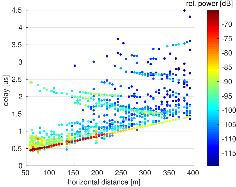
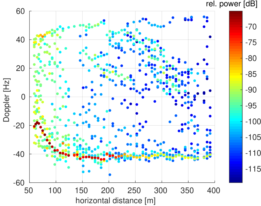
Fig. 6(b) shows the Doppler frequency PSD for the same flight previously considered. The values of the largest components of the Doppler PSD are coherent with the low speed considered for the UAV of . While for the go flights (the ones starting from the BS) the sign of the dominant Doppler components is negative, the return flights (i.e., those starting from most far away points from the BS) exhibit positive values, as expected. The most powerful points in the figure correspond to the contribution of the main (LoS) component and their Doppler values accounts for the UAV speed (it can be seen that the speed at the beginning of the flight is still increasing until reaching a stable value).
Based on the PDP and Doppler frequency PSD, we can obtain the RMS delay spread and the RMS Doppler frequency spread, respectively.
IV-D Root Mean Square Delay Spread
The RMS delay spread, under some circumstances, it is proportional to the error probability due to the delay dispersion [72]. The delay spread is inversely related with the channel coherence bandwidth, hence a high delay spread will affect the cyclic prefix length and produce Inter-Symbol Interference (ISI), requiring the use of more advanced equalization architectures at the receiver. The RMS delay spread is calculated as the normalized second-order central moment of the delay [72]. Following the same approach as in [73], let us firstly define the normalized PDP for the th frame as
| (6) |
being given by Eq. 4. From the result in Eq. 6, the th moment of the delay is
| (7) |
and the RMS delay spread is defined as
| (8) |
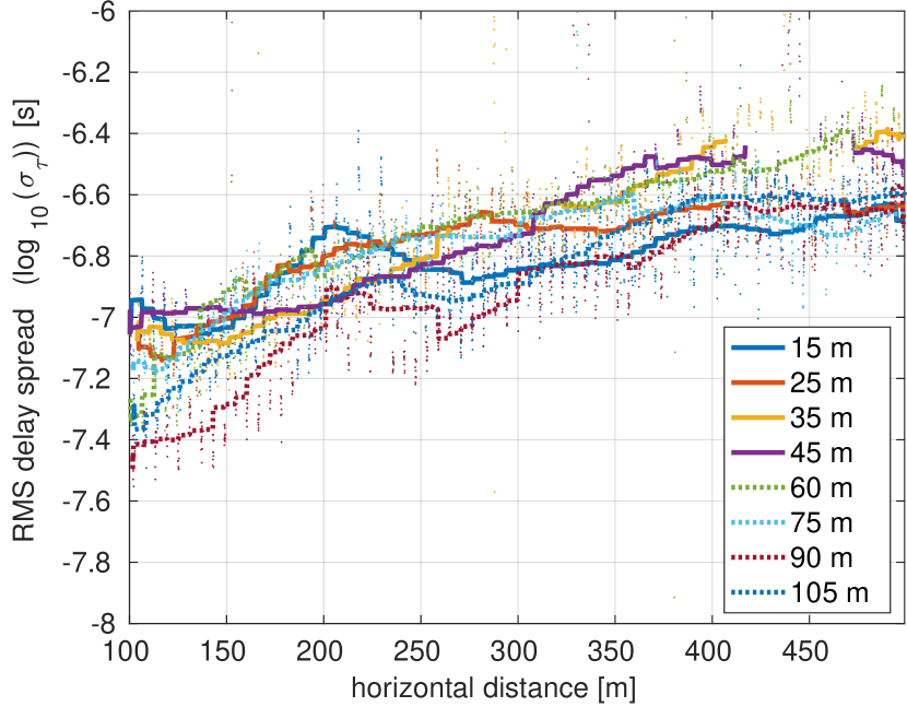
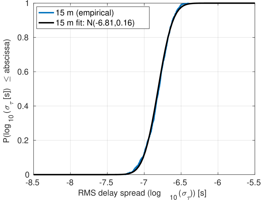
Fig. 7(a) shows the RMS delay spread values for the sample case. There is not a strong dependency with the flight height, although in general the values are slightly lower for the highest heights. It can be seen that, for all the cases, the RMS delay spread increases with the distance to the BS. This can be explained because the LoS MPC becomes less powerful when the distance increases (e.g., see Fig. 6(a)). Fig. 7(b) shows the proposed fittings for some of the empirical CDFs for each cloud of points of the RMS delay spread values. In Table VII we summarize the obtained results for the different environments and transmit antennas. In all cases, normal distributions are used for the fittings. When the directional BS antenna is used, the RMS delay spread for mid-height flights results slightly lower, since the LoS path is more dominant than the non-line-of-sight (NLoS) ones, which can be contributed by the signals transmitted by the sidelobes of the directional antenna at the BS. We can also observe that the RMS delay spread values are slightly lower for the Environment I with respect to the Environment II since the the channel exhibits more clearance for the first case. Finally, a noticeable increase of both the mean and the variance of the RMS delay spread can be appreciated in the Environment II when the UAV crosses the media building for the lowest flight (i.e., the m height one), due to the change from LoS propagation conditions to OLoS.
| Height | Env. I | Env. I | Env. II | Env. II |
|---|---|---|---|---|
| [m] | Omnidir. ant. | Dir. ant | Omnidir. ant. | Dir. ant |
| (LoS) | ||||
| (OLoS) | – | – | ||
IV-E Root Mean Square Doppler Frequency Spread
The Doppler frequency spread is inversely related with the channel coherence time and hence could affect both the maximum usable frame size as well as the duplexing method. It also leads to inter-carrier interference (ICI), hence making it necessary to include ICI cancellation methods at the receiver or more advanced channel equalization techniques. The RMS Doppler Frequency Spread is calculated as the second-order central moment of the Doppler PSD, in a analogous way as that described by Eqs. 6, 7 and 8. Let us define the normalized Doppler PSD for the th frame, by applying a similar strategy as for the delay, as
| (9) |
where is defined as in Eq. 5. From the result in Eq. 9, the th moment of the Doppler is
| (10) |
and the RMS Doppler frequency spread is defined as
| (11) |
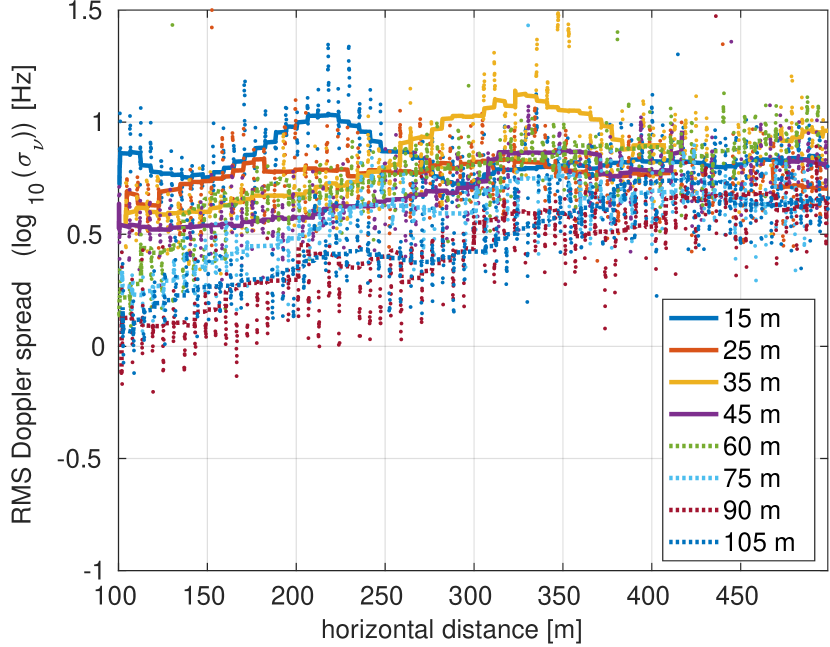
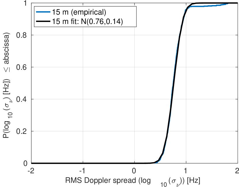
Fig. 8(a) shows the RMS Doppler frequency spread values for the sample case. It can be observed that the RMS Doppler Frequency Spread values tend to decrease as the flight height increases, specially when the UAV is close to the BS. Fig. 8(b) shows a sample proposed fitting for one of the obtained empirical CDFs, being the obtained results for all the cases summarized in Table VIII. In all cases, normal distributions are used for the fittings. The obtained results show that the RMS Doppler Frequency spread decreases when the flight height increases, and that in general it is lower for the Environment I when the omnidirectional antenna is used, being the results more similar for the BS antenna case. Furthermore, the use of the BS antenna can slightly increase the RMS Doppler frequency spread. Table VIII also reveals an increase of the mean and the variance of the RMS Doppler frequency spread when the UAV changes from LoS propagation conditions to OLoS after crossing the media building when the flight height is m.
| Height | Env. I | Env. I | Env. II | Env. II |
|---|---|---|---|---|
| [m] | Omnidir. ant. | Dir. ant | Omnidir. ant. | Dir. ant |
| (LoS) | ||||
| (OLoS) | – | – | ||
IV-F Ricean K-factor
In principle, for both of the considered measurement environments, mainly (possibly obstructed) LoS propagation conditions are assumed during most of the trajectory. Hence, one of the paths exhibits a much higher power level than the others most of the time. In this situation, the fluctuations of that path gain can be assumed to follow a Ricean distribution, which is characterized by a single parameter, namely the Ricean K-factor [75]. More specifically, the K-factor is the ratio of the power in the LoS component or dominant component to the power in the NLoS or the other multipath components [76]. The classical moment-based method proposed in [77] was used to calculate the K-factor.
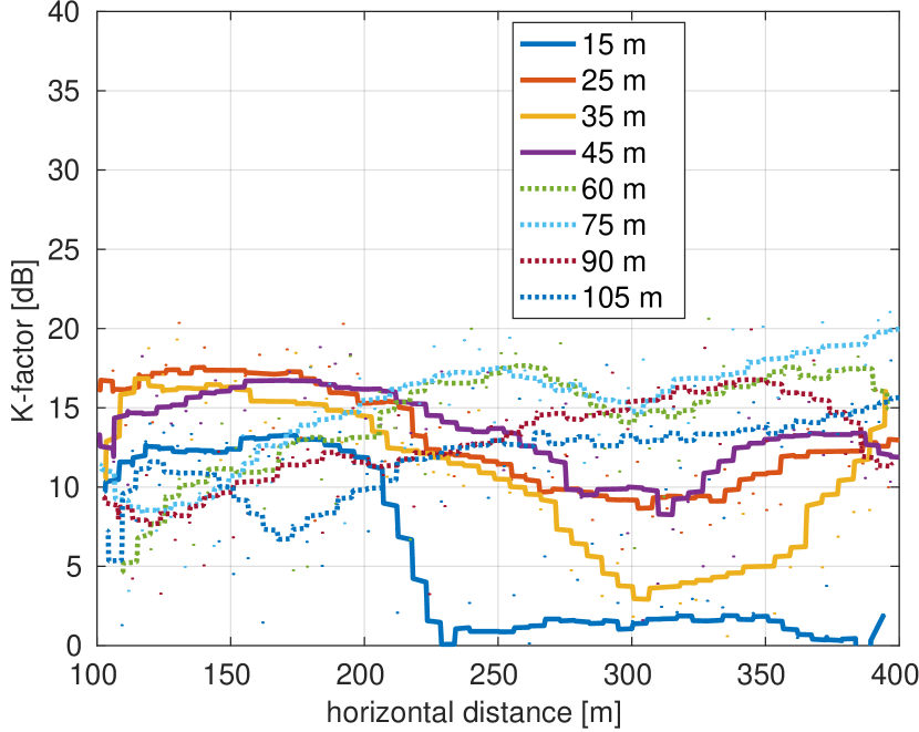
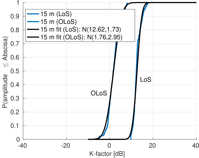
As in previous sections, the K-factor calculation is also divided into two parts when the flight height is m for the Environment II, labeled as LoS and OLoS, respectively. In fact, in order to illustrate this effect, Fig. 9(a) shows the K-factor at different flight heights for the Environment II considering the BS antenna at the transmitter. Noticeably, different behaviors can be observed with the flight height. Firstly, there is a sharp drop in the m case when the UAV crosses the media building, hence moving from the LoS area to the OLoS one. Secondly, it can be seen that for moderate flight heights (below m), the general trend of the K-Factor is to decrease with the horizontal distance. The main reason for this behavior is that the density of buildings close to the last part of the flight is increased, which results in more reflections close in power to the LoS component approaching the UAV. Indeed, this effect is also appreciated for the case of the Environment I. Furthermore, for moderate flight heights (below m– m) in Environment II, there is a local minimum of the K-Factor when the horizontal distance is around m, as shown in Fig. 9(a), which corresponds to the area more close to the library building. This way, in these areas, the reflections caused by the library building became more similar in power to the LoS component (this effect can also be appreciated in Fig. 6(a)) and decrease the K-Factor. Finally, for higher flights, the K-Factor increases with the distance in general when the BS antenna is used, as shown in Fig. 9(a). This is due to the effect of the radiation pattern of the BS antenna. As explained in Section IV-A, the UAV is expected to fall out from the main radiation lobe for low values of the horizontal distance, whereas larger distances may allow to receive some contributions from the main radiation lobe, which results in an increased K-Factor. This is not the case when the omnidirectional antenna is used. In this case, the general trend of the K-Factor is to be decreased with the horizontal distance increasing regardless of the flight height. Fig. 9(b) shows the sample fittings for the obtained empirical CDFs when the flight height is m (in both LoS and OLoS cases).
All the obtained K-factor results are summarized in Table IX. In all cases, Normal distributions are used for the fittings. From the results, it can be seen that, when the omnidirectional antenna is used, the middle-height flights exhibit slightly lower results, whereas the highest flights increase the K-factor, which may be partially caused due to the effect of the library building (consequently with the effects shown in Fig. 9(a)). Since this building is around m height, it is likely to affect less to the highest flights. When the directional antenna is used at the BS, the K-factor results are in general decreased, specially for the highest flights. As in the example shown in Fig. 9(a), the K-Factor for the BS case and high flights increases in general with the horizontal distance, but some values for low horizontal distances can be very reduced. This leads to a lower mean value and an increased variance for the fits in general. Finally, it can be seen that the K-factor does not exhibit as much dependency with the flight height as it could be expected. Indeed, although the channel is expected to be more LoS-alike for higher flights, due to the existence of high buildings in the measurement environments (e.g., the library building or the buildings close to the entrance to the university campus), strong reflections can still be observed at high flight heights, which causes the variation of the K-factor to be not so significant. Even more, in some cases those reflections in high buildings can only be permanently appreciated for high flights, since in lower flights the reflections can be temporarily blocked by other elements of the ground environment in the vicinity of the UAV.
| Height | Env. I | Env. I | Env. II | Env. II |
|---|---|---|---|---|
| [m] | Omnidir. ant. | Dir. ant | Omnidir. ant. | Dir. ant |
| (LoS) | ||||
| (OLoS) | – | – | ||
V Conclusions
In this paper, the air-to-ground channel for low-height small-sized UAVs was studied based on a systematic measurement campaign including horizontal flights at different heights and two different suburban environments. Two antennas were used at the transmitter, which are (a) an omnidirectional antenna, which allows for obtaining an accurate characterization of the channel characteristics and (b) a typical BS directional antenna, which gives insights on the behavior for an individual sector of a BS. The channel for the different measurement environments was characterized based on the path loss, shadow fading, PDP, Doppler frequency PSD, RMS delay spread, RMS Doppler frequency spread and the K-factor. From the results, it can be seen that the ground scenario can severely affect the path loss exponent, specially for low heights. The choose of the antenna type as well as its orientation (in the case of directive ones) is also very relevant depending on the flight height range to be considered. The shadow fading does not show a high dependency with the distance between the UAV and the BS, but it is reduced with the flight height increasing when the omnidirectional antenna is used. Due to the effect of the sidelobes, this effect cannot be observed when the directional antenna is considered. RMS delay and Doppler frequency spreads do not show a strong dependency with the flight height, although they tend to decrease slightly for the highest flight values considered. The use of the directional antenna can help to slightly reduce the RMS delay spread for mid-height flights, leading to decreased error probability due to less delay dispersion. The ground elements can still affect the RMS delay spread even for high flights. Finally, the K-factor, as well as the path loss, are severely affected by the ground elements and the radiation pattern of the antenna at the BS. Due to the reflections in high buildings are still noticeable when the UAV flight height is high, the effect of the flight height on the K-factor could be not so obvious in this kind of environments.
Summing up the propagation results, we can see that the channel characteristics are affected by the ground environment, even for not so low flight heights. Furthermore, it can be seen that the results are influenced by the antenna used at the BS. It can be seen that the use of a directional BS antenna, as usual for ground developments (even for tilt), limits the flight height and distance ranges, and can influence the time and frequency coherence of the channel up to some extent. This way, the use of terrestrial LTE/5G deployments to serve UAVs will probably be subjected to the careful consideration of the antennas configuration at the BS. In this sense, for a typical deployment based on the use of several directional antennas, it may be required to add more antennas to cover a larger height range. In this situation, the provided statistical channel model for the omnidirectional antenna at the BS would be a good approximation to the channel model between the UAV and a BS with several directional antennas for the range of height covered by those directional antennas. Hence, the provided channel model can be used to estimate the actual performance of LTE/5G communication systems for serving UAVs, as we have already done in [78].
Note that, even though we have shown that the analyzed channel characteristics vary with the height and the distance between the UAV and the BS, for most of them the variation is not so significant and the parameters of most of the provided statistical distributions change indeed within a reduced range for realistic flight heights according to the regulations. The channel characteristics that are more dependent with the flight height and the UAV-BS distance are the path loss and the Ricean K-Factor. Except for the cases where this limitation comes from the radiation pattern of the antenna (which should not be the case for a proper BS deployment), indeed the variation is not so directly related with the flight height, but with the distribution of the elements of the ground environment. This way, depending on the distribution and height of the buildings and other architectural elements in the environment, it could be not straightforward to estimate a parameter such as the K-Factor. For example, the K-Factor can be decreased when the flight height increases (which seems not intuitive in principle) since for higher flights the reflections from tall buildings are not blocked by short buildings close to the UAV and hence they become more stable. This leads to the conclusion that time-variant channel models are required for this kind of scenarios, which can predict how the distribution of the MPCs change with time or, equivalently, with the position of the UAV with respect to the ground environment, which is our current work line for the next future works.
References
- [1] Y. Zeng, R. Zhang, and T. J. Lim, “Wireless communications with unmanned aerial vehicles: opportunities and challenges,” IEEE Communications Magazine, vol. 54, no. 5, pp. 36–42, 2016.
- [2] K. P. Valavanis and G. J. Vachtsevanos, Handbook of unmanned aerial vehicles. Springer Publishing Company, Incorporated, 2014.
- [3] S. Hayat, E. Yanmaz, and R. Muzaffar, “Survey on unmanned aerial vehicle networks for civil applications: A communications viewpoint,” IEEE Communications Surveys & Tutorials, vol. 18, no. 4, pp. 2624–2661, 2016.
- [4] A. Ryan, M. Zennaro, A. Howell, R. Sengupta, and J. K. Hedrick, “An overview of emerging results in cooperative UAV control,” in 2004 43rd IEEE Conference on Decision and Control (CDC)(IEEE Cat. No. 04CH37601), vol. 1. IEEE, 2004, pp. 602–607.
- [5] M. T. DeGarmo, “Issues concerning integration of unmanned aerial vehicles in civil airspace,” Center for Advanced Aviation System Development, p. 4, 2004.
- [6] M. A. Kovacina, D. Palmer, G. Yang, and R. Vaidyanathan, “Multi-agent control algorithms for chemical cloud detection and mapping using unmanned air vehicles,” in IEEE/RSJ International Conference on Intelligent Robots and Systems, vol. 3. IEEE, 2002, pp. 2782–2788.
- [7] M. G.-R. H. Fretes, J. Rodríguez-Piñeiro, J. Rodas, and R. Gregor, “Automatic scene reconstruction algorithm for planialtimetric applications,” in XXIII IEEE Congress of the Chilean Association of Automatic Control (ICA-ACCA 2018), Concepción, Chile, October 2018, online access: http://dx.doi.org/10.1109/ICA-ACCA.2018.8609706.
- [8] E. Paiva, M. Llano, J. Rodas, R. Gregor, J. Rodríguez-Piñeiro, and M. Gómez-Redondo, “Design and implementation of a VTOL flight transition mechanism and development of a mathematical model for a tilt rotor UAV,” in XXIII IEEE Congress of the Chilean Association of Automatic Control (ICA-ACCA 2018), Concepción, Chile, October 2018, online access: http://dx.doi.org/10.1109/ICA-ACCA.2018.8609836.
- [9] A. Tariq, S. Osama, and A. Gillani, “Development of a low cost and light weight UAV for photogrammetry and precision land mapping using aerial imagery,” in 2016 International Conference on Frontiers of Information Technology (FIT). IEEE, 2016, pp. 360–364.
- [10] A. Segales, R. Gregor, J. Rodas, D. Gregor, and S. Toledo, “Implementation of a low cost UAV for photogrammetry measurement applications,” in 2016 International Conference on Unmanned Aircraft Systems (ICUAS). IEEE, 2016, pp. 926–932.
- [11] U. D. of Transportation, “Unmanned aircraft system (UAS) service demand 2015-2035: Literature review & projections of future usage,” Tech. Rep., Sep 2013, v.0.1 DOT-VNTSC-DoD-13-01.
- [12] C. Zhang and J. M. Kovacs, “The application of small unmanned aerial systems for precision agriculture: a review,” Precision agriculture, vol. 13, no. 6, pp. 693–712, 2012.
- [13] A. Osseiran, F. Boccardi, V. Braun, K. Kusume, P. Marsch, M. Maternia, O. Queseth, M. Schellmann, H. Schotten, H. Taoka et al., “Scenarios for 5G mobile and wireless communications: the vision of the METIS project,” IEEE Communications Magazine, vol. 52, no. 5, pp. 26–35, 2014.
- [14] P. Zhan, K. Yu, and A. L. Swindlehurst, “Wireless relay communications with unmanned aerial vehicles: Performance and optimization,” IEEE Transactions on Aerospace and Electronic Systems, vol. 47, no. 3, pp. 2068–2085, 2011.
- [15] Y. Zhou, N. Cheng, N. Lu, and X. S. Shen, “Multi-UAV-aided networks: aerial-ground cooperative vehicular networking architecture,” IEEE Vehicular Technology Magazine, vol. 10, no. 4, pp. 36–44, 2015.
- [16] R. Lee, J. Manner, J. Kim, B. Hurley, P. Amodio, and K. Anderson, “Role of deployable aerial communications architecture in emergency communications and recommended next steps,” Federal Communications Commission, 2011.
- [17] R. C. Palat, A. Annamalau, and J. Reed, “Cooperative relaying for ad-hoc ground networks using swarm UAVs,” in MILCOM 2005-2005 IEEE Military Communications Conference. IEEE, 2005, pp. 1588–1594.
- [18] D. L. Gu, G. Pei, H. Ly, M. Gerla, B. Zhang, and X. Hong, “UAV aided intelligent routing for ad-hoc wireless network in single-area theater,” in 2000 IEEE Wireless Communications and Networking Conference. Conference Record (Cat. No. 00TH8540), vol. 3. IEEE, 2000, pp. 1220–1225.
- [19] A. Valcarce, T. Rasheed, K. Gomez, S. Kandeepan, L. Reynaud, R. Hermenier, A. Munari, M. Mohorcic, M. Smolnikar, and I. Bucaille, “Airborne base stations for emergency and temporary events,” in International Conference on Personal Satellite Services. Springer, 2013, pp. 13–25.
- [20] X. Lin, V. Yajnanarayana, S. D. Muruganathan, S. Gao, H. Asplund, H.-L. Maattanen, S. Euler, Y.-P. E. Wang et al., “The sky is not the limit: LTE for unmanned aerial vehicles,” IEEE Communications Magazine, vol. 56, no. 4, pp. 204–210, 2018.
- [21] E. Yanmaz, R. Kuschnig, and C. Bettstetter, “Achieving air-ground communications in 802.11 networks with three-dimensional aerial mobility,” in INFOCOM, 2013 Proceedings IEEE. IEEE, 2013, pp. 120–124.
- [22] NTT DOCOMO Inc. and Ericsson, “New SID on enhanced support for aerial vehicles,” Tech. Rep., 2017, 3GPP RP-170779.
- [23] NTT DOCOMO Inc. and Ericsson, “New WID on enhanced LTE support for aerial vehicles,” Tech. Rep., 2017, 3GPP, RP-172669.
- [24] X. Cai, J. Rodríguez-Piñeiro, X. Yin, N. Wang, B. Ai, G. F. Pedersen, and A. P. Yuste, “An empirical air-to-ground channel model based on passive measurements in LTE,” IEEE Transactions on Vehicular Technology, vol. 68, no. 2, pp. 1140–1154, 2019, online access: http://dx.doi.org/10.1109/TVT.2018.2886961.
- [25] E. R. S. Group et al., “Roadmap for the integration of civil remotely-piloted aircraft systems into the European aviation system,” European RPAS Steering Group, Tech. Rep, 2013.
- [26] R. Amorim, H. Nguyen, P. Mogensen, I. Z. Kovács, J. Wigard, and T. B. Sorensen, “Radio channel modeling for UAV communication over cellular networks,” IEEE Wireless Communications Letters, vol. 6, no. 4, pp. 514–517, Aug 2017.
- [27] K. Welch, “Evolving cellular technologies for safer drone operation,” October 2016, qualcomm 5G White Paper Presentation.
- [28] B. Van Der Bergh, A. Chiumento, and S. Pollin, “LTE in the sky: trading off propagation benefits with interference costs for aerial nodes,” IEEE Communications Magazine, vol. 54, no. 5, pp. 44–50, 2016.
- [29] N. Docomo and Ericsson, “Study on enhanced LTE support for aerial vehicles,” Tech. Rep., March 2017, rP-170779.
- [30] D. W. Matolak and R. Sun, “Initial results for air-ground channel measurements & modeling for unmanned aircraft systems: Over-sea,” in IEEE Aerospace Conference, 2014, pp. 1–15.
- [31] 3GPP, “Study on channel model for frequencies from 0.5 to 100 GHz,” Tech. Rep., March 2017, 3GPP TR 38.901 V1.0.1.
- [32] Q. Feng, J. McGeehan, E. K. Tameh, and A. R. Nix, “Path loss models for air-to-ground radio channels in urban environments,” in IEEE Vehicular Technology Conference, vol. 6, 2006, pp. 2901–2905.
- [33] E. Tameh, A. Nix, and M. Beach, “A 3-D integrated macro and microcellular propagation model, based on the use of photogrammetric terrain and building data,” in IEEE Vehicular Technology Conference, vol. 3, 1997, pp. 1957–1961.
- [34] W. Khawaja, O. Ozdemir, and I. Guvenc, “UAV air-to-ground channel characterization for mmWave systems,” arXiv preprint arXiv:1707.04621, 2017.
- [35] A. Al-Hourani and K. Gomez, “Modeling cellular-to-UAV path-loss for suburban environments,” IEEE Wireless Communications Letters, vol. PP, no. 99, pp. 1–1, 2017.
- [36] E. Yanmaz, R. Kuschnig, and C. Bettstetter, “Channel measurements over 802.11 a-based uav-to-ground links,” in GLOBECOM Workshops (GC Wkshps), 2011 IEEE. IEEE, 2011, pp. 1280–1284.
- [37] W. Khawaja, I. Guvenc, and D. Matolak, “UWB channel sounding and modeling for UAV air-to-ground propagation channels,” in IEEE Global Communications Conference (GLOBECOM), 2016, pp. 1–7.
- [38] N. Goddemeier, K. Daniel, and C. Wietfeld, “Role-based connectivity management with realistic air-to-ground channels for cooperative UAVs,” IEEE Journal on Selected Areas in Communications, vol. 30, no. 5, pp. 951–963, 2012.
- [39] T. Izydorczyk, F. M. L. Tavares, G. Berardinelli, M. C. Bucur, and P. E. Mogensen, “Angular distribution of cellular signals for UAVs in urban and rural scenarios,” in European Conference on Antenna and Propagation (eucap), 2019.
- [40] T. Izydorczyk, M. Bucur, F. M. Tavares, G. Berardinelli, and P. Mogensen, “Experimental evaluation of multi-antenna receivers for UAV communication in live LTE networks,” in 2018 IEEE Globecom Workshops (GC Wkshps). IEEE, 2018, pp. 1–6.
- [41] D. W. Matolak and R. Sun, “Air-ground channel characterization for unmanned aircraft systems: The near-urban environment,” in IEEE Military Communications Conference, 2015, pp. 1656–1660.
- [42] D. W. Matolak and R. Sun, “Air-ground channel characterization for unmanned aircraft systems: The hilly suburban environment,” in Vehicular Technology Conference (VTC Fall). IEEE, 2014, pp. 1–5.
- [43] D. W. Matolak and R. Sun, “Air-ground channels for UAS: Summary of measurements and models for L-and C-bands,” in IEEE Integrated Communications Navigation and Surveillance (ICNS), 2016, pp. 8B2–1.
- [44] R. Sun and D. W. Matolak, “Air–ground channel characterization for unmanned aircraft systems part II: Hilly and mountainous settings,” IEEE Transactions on Vehicular Technology, vol. 66, no. 3, pp. 1913–1925, 2017.
- [45] D. W. Matolak and R. Sun, “Air-ground channel characterization for unmanned aircraft systems-part I: Methods, measurements, and models for over-water settings,” IEEE Transactions on Vehicular Technology, vol. 66, no. 1, pp. 26–44, 2017.
- [46] D. W. Matolak and R. Sun, “Air-ground channel characterization for unmanned aircraft systems-part III: The suburban and near-urban environments,” IEEE Transactions on Vehicular Technology, vol. 66, no. 8, pp. 6607–6618, 2017.
- [47] D. W. Matolak and R. Sun, “Air-ground channel measurements & modeling for UAS,” in IEEE Integrated Communications, Navigation and Surveillance Conference (ICNS), 2013, pp. 1–9.
- [48] D. W. Matolak and R. Sun, “Unmanned aircraft systems: Air-ground channel characterization for future applications,” IEEE Vehicular Technology Magazine, vol. 10, no. 2, pp. 79–85, 2015.
- [49] D. W. Matolak and R. Sun, “Air-ground channel characterization for unmanned aircraft systems: The over-freshwater setting,” in IEEE Integrated Communications, Navigation and Surveillance Conference (ICNS), 2014, pp. K1–1.
- [50] D. W. Matolak, “Air-ground channels & models: Comprehensive review and considerations for unmanned aircraft systems,” in IEEE Aerospace Conference, 2012, pp. 1–17.
- [51] International Telecommunication Union (ITU), Radiocommunication section (ITU-R), “Recommendation ITU-R V.431-8: Nomenclature of the frequency and wavelength bands used in telecommunications,” ITU-R, Tech. Rep. ITU-R V.431-8, 2015.
- [52] N. Schneckenburger, T. Jost, U.-C. Fiebig, G. Del Galdo, H. Jamal, D. Matolak, and R. Sun, “Modeling the air-ground multipath channel,” in IEEE European Conference on Antennas and Propagation (EUCAP), 2017, pp. 1434–1438.
- [53] N. Schneckenburger, T. Jost, D. Shutin, M. Walter, T. Thiasiriphet, M. Schnell, and U.-C. Fiebig, “Measurement of the L-band air-to-ground channel for positioning applications,” IEEE Transactions on Aerospace and Electronic Systems, vol. 52, no. 5, pp. 2281–2297, 2016.
- [54] N. Schneckenburger, D. Shutin, T. Jost, M. Walter, T. Thiasiriphet, A. Filip, and M. Schnell, “From l-band measurements to a preliminary channel model for apnt,” ION GNSS+,(Tampa (FL), USA), 2014.
- [55] X. Cai, N. Wang, J. Rodríguez-Piñeiro, X. Yin, A. Pérez-Yuste, W. Fan, G. Zhang, and G. F. Pedersen, “Low altitude air-to-ground channel characterization in LTE network,” in 13th European Conference on Antennas and Propagation (EuCAP 2019), Krakow, Poland, March-April 2019.
- [56] X. Ye, X. Cai, X. Yin, J. Rodríguez-Piñeiro, L. Tian, and J. Dou, “Air-to-ground big-data-assisted channel modeling based on passive sounding in LTE networks,” in 2017 IEEE Global Communications Conference (GLOBECOM 2017), Singapore, December 2017, pp. 1–6, workshop “Vehicular Communications based on 5G”. Online access: http://dx.doi.org/10.1109/GLOCOMW.2017.8269204.
- [57] N. Wang, X. Yin, X. Cai, J. Rodríguez-Piñeiro, and A. P. Yuste, “A novel air-to-ground channel modeling method based on graph model,” in 13th European Conference on Antennas and Propagation (EuCAP 2019), Krakow, Poland, March-April 2019.
- [58] Y. Miao, W. Fan, J. Rodríguez-Piñeiro, X. Yin, and Y. Gong, “Emulating UAV air-to-ground radio channel in multi-probe anechoic chamber,” in 2018 IEEE Global Communications Conference (GLOBECOM 2018), Abu Dhabi, EUA, December 2018, online access: http://dx.doi.org/10.1109/GLOCOMW.2018.8644381.
- [59] M. Wentz and M. Stojanovic, “A MIMO radio channel model for low-altitude air-to-ground communication systems,” in IEEE Vehicular Technology Conference (VTC Fall), 2015, pp. 1–6.
- [60] W. G. Newhall and J. H. Reed, “A geometric air-to-ground radio channel model,” in MILCOM 2002. Proceedings, vol. 1, Oct 2002, pp. 632–636 vol.1.
- [61] W. Newhall, “Radio channel measurements and modeling for smart-antenna array systems using a software radio receiver.”
- [62] W. G. Newhall, R. Mostafa, C. Dietrich, C. R. Anderson, K. Dietze, G. Joshi, and J. H. Reed, “Wideband air-to-ground radio channel measurements using an antenna array at 2 GHz for low-altitude operations,” in IEEE Military Communications Conference, vol. 2, 2003, pp. 1422–1427.
- [63] H. Kung, C.-K. Lin, T.-H. Lin, S. J. Tarsa, and D. Vlah, “Measuring diversity on a low-altitude UAV in a ground-to-air wireless 802.11 mesh network,” in IEEE GLOBECOM Workshops (GC Wkshps), 2010, pp. 1799–1804.
- [64] J. Chen, B. Daneshrad, and W. Zhu, “MIMO performance evaluation for airborne wireless communication systems,” in IEEE Military Communications Conference, 2011, pp. 1827–1832.
- [65] T. J. Willink, C. C. Squires, G. W. Colman, and M. T. Muccio, “Measurement and characterization of low-altitude air-to-ground MIMO channels,” IEEE Transactions on Vehicular Technology, vol. 65, no. 4, pp. 2637–2648, 2016.
- [66] T. Domínguez-Bolaño, J. Rodríguez-Piñeiro, J. A. García-Naya, and L. Castedo, “The GTEC 5G link-level simulator,” in 1st International Workshop on Link- and System Level Simulations (IWSLS2 2016), Vienna, Austria, July 2016, online access: http://dx.doi.org/10.1109/IWSLS.2016.7801585.
- [67] “GTEC Testbed Project,” https://bitbucket.org/tomas_bolano/gtec_testbed_public.git.
- [68] B. H. Fleury, M. Tschudin, R. Heddergott, D. Dahlhaus, and K. I. Pedersen, “Channel parameter estimation in mobile radio environments using the SAGE algorithm,” IEEE J. Sel. Areas Commun., vol. 17, no. 3, pp. 434–450, 1999.
- [69] ETSI, “TS 136 213 V14.2.0: LTE; E-UTRA; Physical layer procedures,” April 2017.
- [70] T. S. Rappaport et al., Wireless communications: principles and practice. Prentice Hall PTR New Jersey, 1996, vol. 2.
- [71] P. J. Huber, Robust Statistics. Wiley-Interscience, 1981.
- [72] A. F. Molisch, Wireless communications. John Wiley & Sons, 2012, vol. 34.
- [73] T. Domínguez-Bolaño, J. Rodríguez-Piñeiro, J. A. García-Naya, X. Yin, and L. Castedo, “Measurement-based characterization of train-to-infrastructure 2.6 GHz propagation channel in a modern subway station,” IEEE Access, vol. 6, pp. 52 814–52 830, September 2018, online access: http://dx.doi.org/10.1109/ACCESS.2018.2870564.
- [74] A. Meijerink and A. F. Molisch, “On the physical interpretation of the Saleh–Valenzuela model and the definition of its power delay profiles,” IEEE Trans. Antennas Propag., vol. 62, no. 9, pp. 4780–4793, 2014.
- [75] T. Domínguez-Bolaño, J. Rodríguez-Piñeiro, J. A. García-Naya, and L. Castedo, “Experimental characterization and modeling of LTE wireless links in high-speed trains,” Wireless Communications and Mobile Computing, vol. 2017, no. 5079130, pp. 1–20, 2017, special Issue on Wireless Communications in Transportation Systems. Online access: http://dx.doi.org/10.1155/2017/5079130.
- [76] X. Cai, X. Yin, X. Cheng, and A. P. Yuste, “An empirical random-cluster model for subway channels based on passive measurements in UMTS,” IEEE Transactions on Communications, vol. 64, no. 8, pp. 3563–3575, Aug 2016.
- [77] L. J. Greenstein, D. G. Michelson, and V. Erceg, “Moment-method estimation of the Ricean K-factor,” IEEE Communications Letters, vol. 3, no. 6, pp. 175–176, June 1999.
- [78] Z. Huang, J. Rodríguez-Piñeiro, T. Domínguez-Bolaño, X. Yin, D. Matolak, and J. Lee, “Performance of 5G terrestrial network deployments for serving UAV communications,” in 14th European Conference on Antennas and Propagation (EuCAP 2020), Copenhagen, Denmark, March 2020, accepted for publication.
![[Uncaptioned image]](/html/2007.11502/assets/xose_bn.jpg) |
José Rodríguez-Piñeiro received the B.Sc. on Telecommunications and the M.Sc. Degree in Signal Processing Applications for Communications from the University of Vigo (Pontevedra, Spain), in 2009 and 2011, respectively. Between June 2008 and July 2011, he was a researcher at the Department of Signal and Communications, University of Vigo (Pontevedra, Spain). From October 2011 he was a researcher at the Group of Electronics Technology and Communications of the University of A Coruña (UDC), obtaining his Ph.D. degree with the distinction “Doctor with European Mention” in 2016. After obtaining his Ph.D. degree with the he continued working as a Postdoctoral researcher at the same group until July 2017. On August 2017 he joined the College of Electronics and Information Engineering, Tongji University (P.R. China), becoming an Assistant Professor in 2020. From November 2012 he also collaborates with the Department of Power and Control Systems, National University of Asunción (Paraguay) in both teaching and research. He is the coauthor of more than 50 papers in peer-reviewed international journals and conferences. He is also a member of the research team in more than 25 research projects funded by public organizations and private companies. He was awarded with 6 predoctoral, postdoctoral and research stay grants. His research interests include experimental evaluation of digital mobile communications, especially for high mobility environments, including terrestrial and aerial vehicular scenarios. |
![[Uncaptioned image]](/html/2007.11502/assets/tomas.jpg) |
Tomás Domínguez-Bolaño received the B.S degree in Computer Engineering and the Ph.D. in Computer Engineering (with the distinction “Doctor with European Mention”) from the University of A Coruña, A Coruña, Spain, in 2014 and 2018, respectively. Since 2014 he has been with the Group of Electronics Technology and Communications. In 2018 he was a Visiting Scholar with Tongji University, Shanghai, China. He is an author of more than 15 papers in peer-reviewed international journals and conferences. He was awarded with a predoctoral grant and two research-stay grants. His research interests include channel measurements, parameter estimation and modeling and experimental evaluation of wireless communication systems. |
![[Uncaptioned image]](/html/2007.11502/assets/xuesong_bn.jpg) |
Xuesong Cai received the B.S. degree and the Ph.D. degree (Hons.) from Tongji University, Shanghai, China, in 2013 and 2018, respectively. In 2015, he conducted a three-month internship with Huawei Technologies, Shanghai, China. He was also a Visiting Scholar with Universidad Politécnica de Madrid, Madrid, Spain in 2016. From 2018-2020, he was a postdoctoral research fellow with the APMS section, Department of Electronic Systems, Aalborg University (AAU), Aalborg, Denmark. Since April 2020, he has been a postdoctoral fellow with the Wireless Communication Networks Section, Department of Electronic Systems, AAU, cooperating with Nokia Bell Labs. His research interests include propagation channel measurement, high-resolution parameter estimation, channel characterization, channel modeling and over-the-air emulation for wireless communications. Dr. Cai was a recipient of the Chinese National Scholarship for Ph.D. Candidates and Excellent Student award in 2016, the Excellent Student award and the “ZTE Fantastic Algorithm” award in 2017, the Outstanding Doctorate Graduate awarded by Shanghai Municipal Education Commission and “ZTE Blue Sword-Future Leaders Plan” in 2018, and the “Seal of Excellence” with the European Horizon 2020’s Marie Skłodowska-Curie actions call in 2019. |
![[Uncaptioned image]](/html/2007.11502/assets/zeyu_bn.jpg) |
Zeyu Huang received the B.S. degree in electronics and information engineering from Tongji University, Shanghai, China, in 2015. Since 2017 he was with the College of Electronics and Information Engineering, Tongji University (P.R. China), obtaining his M.Sc. degree in 2020. He was accepted as a Ph.D. student at Technische Universität Wien (Vienna, Austria) in 2020. He co-authored 3 papers in peer-reviewed international journals and conferences and he was a member of the research team in 7 research projects. His research interests include communications channel measurement and simulation, parameter estimation of communication channels, channel modeling and the use of meta-materials for communications. |
![[Uncaptioned image]](/html/2007.11502/assets/xuefeng.jpg) |
Xuefeng Yin (S’01–M’06) received the Bachelor’s degree in optoelectronics engineering from Huazhong University of Science and Technology, Wuhan, China, in 1995, and the Master of Science degree in digital communications and the Ph.D. in wireless communications from Aalborg University, Aalborg, Denmark, in 2002 and 2006, respectively. From 2006 to 2008, he was an Assistant Professor with Aalborg University. In 2008, he joined the College of Electronics and Information Engineering, Tongji University, Shanghai, China. He became a Full Professor in 2016 and has been the Vice Dean of the college since then. His research interests include high-resolution parameter estimation for propagation channels, measurement-based channel characterization and stochastic modeling for 5G wireless communications, channel simulation based on random graph models, radar signal processing, and target recognition. He has authored or coauthored more than 150 technical papers and coauthored the book Propagation Channel Characterization, Parameter Estimation and Modeling for Wireless Communications (Wiley, 2016). |