The origin of jerky dislocation motion in high-entropy alloys
Abstract
Dislocations in single-phase concentrated random alloys, including high- entropy alloys (HEAs), repeatedly encounter pinning during glide, resulting in jerky dislocation motion. While solute-dislocation interaction is well understood in conventional alloys, the origin of individual pinning points in concentrated random alloys is a matter of debate. In this work, we investigate the origin of dislocation pinning in the CoCrFeMnNi HEA. In- situ transmission electron microscopy studies reveal wavy dislocation lines and a jagged glide motion under external loading, even though no segregation or clustering is found around Shockley partial dislocations. Atomistic simulations reproduce the jerky dislocation motion and link the repeated pinning to local fluctuations in the Peierls friction. We demonstrate that the density of high local Peierls friction is proportional to the critical stress required for dislocation glide and the dislocation mobility.
1 Introduction
High- and medium-entropy alloys (HEAs and MEAs) are a new class of metallic materials that contain multiple elements at high concentrations and form solid solutions[1] in contrast to conventional alloys that typically consist of a single principal element with low concentrations of secondary elements. Since entropy is not always the decisive design parameter, they are a subclass of concentrated random alloys. Several HEAs outrival the mechanical properties of conventional alloys, some possess exclusive property combinations such as high strength and high ductility—even down to cryogenic temperatures[2, 3, 4, 5, 6]. The origin of the high strength of HEAs is key for materials design but is still controversially discussed in the community[7, 8, 9, 10, 11]. There are, however, four different origins explored in the literature to date:
-
1.
Short-range ordering (SRO), i.e., a preferred ordering in the atomic-sized neighborhood, is well known to lead to a strength increase in conventional alloys[12]. This strengthening mechanism has been reported for the CoCrNi, a subsystem of the Cantor (CoCrFeMnNi) alloy[7, 9, 13]. Since trains of dislocations traveling on the same plane were observed in this system, it is argued that the first dislocation gliding on a plane destroys SRO within that plane and facilitates the glide of subsequent dislocations[14]. Yin and Curtin[8], on the other hand, showed that the extraordinary strength of CoCrNi[2] can also be explained based on solid solution strengthening without resorting to SRO.
-
2.
Indeed, dislocation pinning and the resulting strengthening are also observed in ideally random alloys[2]. Li et al.[7] reported that even in a perfectly random CoCrNi alloy some preferential atomic arrangements, in the case of Co and Cr, exist, and breaking these randomly appearing favorable bonds requires additional energy.
-
3.
The unexpected wide range of stacking fault (SF) energies observed for HEAs could provide an alternative explanation for the pinning experienced by dislocations[15, 16]. The resulting wavy dislocation lines have been observed for different HEAs in transmission electron microscopy (TEM) experiments[16, 17, 18] and atomistic simulations[7, 19, 20]. Li et al.[7] argued that the wide range of stacking fault energy (SFE) causes peaks in the energy landscape where lattice friction becomes enhanced locally. Therefore, dislocation segments need to unzip from the local barriers while gliding. Such a mechanism would only exist in HEAs, but not in conventional dilute solid solutions as their local fluctuations in the SF energy remain comparatively small.
-
4.
Lastly, the solid solution strengthening model developed by Varvenne et al.[21] predicts the flow stresses in an HEA solely based on misfit volumes and elastic properties. The dominating mechanism of solid solution strengthening in HEAs is intricate as it becomes impossible to define distinct matrix and solute atoms. A Labusch-type weak interaction[22] between solute atoms and dislocations is assumed in Varvenne’s model. Here, the dislocation line interacts with the whole field of solutes within its elastic interaction range at the same time. This is opposite to the strong-pinning model from Fleischer[23] where each solute corresponds to a site where the dislocation line is pinned.
In this study, we investigate the repeated local pinning along subsequent dislocations in the face-centered cubic (FCC) CoCrFeMnNi HEA by combining in- situ TEM deformation, atomic resolution analytical scanning transmission electron microscopy (STEM), and atomistic simulations. In-situ TEM deformation tests reveal wavy dislocation lines and a jagged dislocation motion under an applied tensile strain, although no indication of SRO is found by atomic resolution STEM energy-dispersive X-ray spectroscopy (EDS). Atomistic computer simulations reproduce the jerky dislocation motion with repeated pinning in random samples without SRO. The underlying mechanism is directly linked to local fluctuations in Peierls (force/friction) barriers, which lead to dislocation pinning points in concentrated random alloys. We further show their relation to the critical stress needed to move a dislocation line and the resulting mobility. While not a full solid solution strengthening model, the atomic fluctuations in frictional forces provide predictive design guidelines to tailor the dislocation pinning in HEAs.
2 Methods
2.1 Fabrication of CoCrFeMnNi single crystal
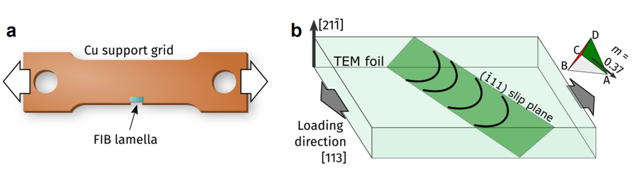
A single crystal CoCrFeMnNi HEA was produced by using the Czochralski method from an equiatomic melt of high-purity elements. The composition of Fe, Co, Cr, Mn, and Ni is 24, 24, 20, 12, 20 , respectively, measured by both STEM-EDS and atom probe tomography[17, 24]. In situ TEM straining samples were prepared by focused ion beam (FIB) site-specific lift-out method[25] that utilizes a 30 and Ga ion beam (JIB-4610F, JEOL). A thin lamella with a size of several micrometers was glued on a custom-made Cu grid by Pt deposition.
2.2 In situ TEM tensile experiments
In situ tensile straining tests were carried out in an aberration-corrected TEM operated at (JEM-ARM300CF, JEOL) equipped with a straining holder (Model 654, Gatan). In situ TEM movies were recorded with a high-speed camera at a frame rate of 50 frames per second and 2k resolution (Oneview, Gatan). The displacement of the whole large sample support was controlled by a step motor whose resolution was . The straining was interrupted intermittently to stabilize the stage and observe dislocation glide motion. No quantitative load-displacement data can be obtained during the deformation.
The contrast of dislocations in TEM images and videos is enhanced by image processing. Firstly, the background noise from the FIB damage is removed by using direct subtraction of the last frame after aligning all frames using the cross-correlation method. Then, a Gaussian filter is used to blur the remaining noise. To extract dislocation positions as shown in Fig. 1b, a ridge detection filter is used after applying an additional Gaussian filter.
2.3 STEM EDS experiments
The atomic-resolution STEM EDS chemical mapping was carried out on a JEM-ARM 200F (JEOL) equipped with a spherical aberration corrector (ASCOR, CEOS) and energy dispersive X-ray spectrometer (JED-EDS, JEOL). Multi-frame EDS maps were acquired for a half-hour by using dual-type EDS detectors (the effective X-ray detection area of a for each detector) with a large effective solid angle () and a highly focused electron probe () at the electron dose rate of . The resulting elemental maps were obtained by the multiple frame summation up to frames with pixels resolution and the acquisition time of per pixel ( in maximum as a total acquisition time). Multi-frame EDS maps were averaged by correcting the frame-to-frame displacement caused by sample drift during acquisition. The averaged X-ray count of each element was converted to the composition by calibrating the k-factor, which accounts for the different X-ray yields of each element. The background noise floor in each composition map was suppressed by averaging every neighboring pixels.
2.4 Atomistic simulations
The equimolar CoCrFeMnNi HEA and its subsystems were all simulated based on the 2NN MEAM[26] interatomic potential by Choi et al.[27], the CoCrCuFeNi[20, 28] and the Co30Fe17Ni37Ti17[19, 29] HEA are based on the Farkas and Caro[28] or Zhou et al.[29] EAM potentials[30, 31], respectively, to exclude erroneous correlations from a given parametrization. All simulations were run in LAMMPS[32]. Samples were prepared using ATOMSK[33], and post-processing was based on algorithms implemented in OVITO[34], and accelerated by PARALLEL[35].
2.5 Virtual TEM lamella
The large-scale sample shown in Fig. 1 measurements had initial dimensions of of pristine FCC lattice oriented \hkl[-1-2-3], \hkl[1-2-1], \hkl[412] along , , and , respectively. This gave approximately lattice sites, filled with either CoCrFeMnNi or CoNi alloy. A surface notch with an inclination of was cut into the plane. This surface notch was aligned with a \hkl111 glide plane in the sample. To mimic the experimental conditions, the x- and z-directions were taken as open surface boundaries, while the y-direction was set to periodic boundary conditions. This sample geometry is schematically shown in Supplementary Fig. S2a.
After equilibration for at or in the NVT ensemble, the sample was subjected to uniaxial strain along y up to a strain of 0.06 using an engineering strain rate of [36], and a constant time step length of . Dislocation lines were extracted every during straining using the dislocation extraction algorithm DXA[37, 38].
2.6 Shear of an edge dislocation
To cut a dislocation into the samples, a half-plane was inserted into an FCC crystal resulting in a misfit edge dislocation following the geometry shown in Supplementary Fig. S2b[39]. The resulting dislocation had a Burgers vector along \hkl[1-10] (corresponding to the -direction) with a line direction of \hkl[11-2] (corresponding to the -direction).
Two different sample dimensions were considered for the isolated dislocation simulations. The smaller sample contained 477600 atoms with periodic boundary conditions along \hkl[1-10] () and \hkl[11-2] () directions and an open boundary along the \hkl[111] () direction. This sample was built from unit cells in each of those directions, respectively. The larger sample had the same crystallographic orientations and boundary conditions, but the total size was increased to unit cells leading to atoms. In both cases, the lattice sites were filled with the desired atomic species to create a random solid solution.
All samples were annealed for at using a time step. During this annealing and the subsequent shear simulations the surface layers were thermostatted using a Langevin thermostat[40], while the atoms in the center of the sample were integrated in the NVE ensemble.
After equilibration, a ramping shear force was applied to each atom in the outer surface layer. This force pointed in the x-direction (cf. Supplementary Fig. S2b) and was ramped from 0 to over . From these shear ramp simulations, the critical force to initiate dislocation glide was determined.
Once this critical force was established, a second constant force simulation was started. Here, the applied shear force was first ramped from 0 to with a rate of .Afterward, it was held for .
2.7 GSF surface calculation
The global and atomic GSF curves were calculated for the two differently sized samples presented in the previous section before dislocation insertion (Supplementary Fig. S2b).
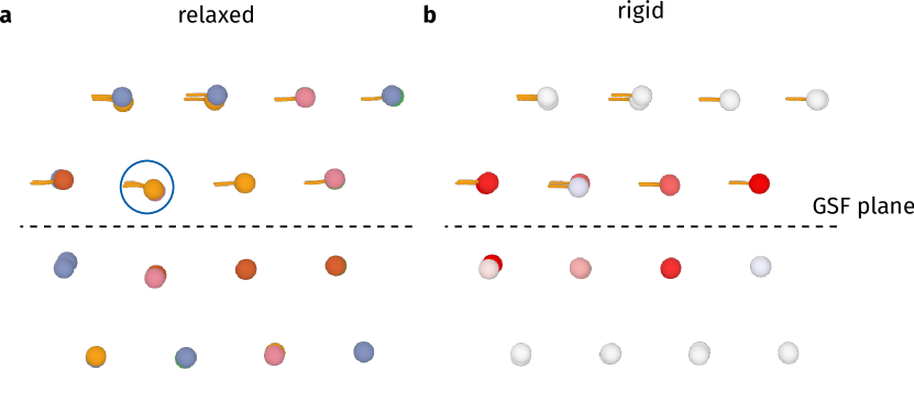
For a GSF calculation, the sample is split into two crystallites. One is above the \hkl¡111¿ GSF plane, while the other one is located below this plane. Applying the conventional simulation methodology prevents the atomic relaxation during rigid displacement of the two crystallites within the GSF plane[41], however, the relaxation of the atoms normal to the GSF remains unconstrained. One problem that arose, applying this methodology, was that the atoms in the disordered alloy relaxed into different intermediate states. While this effect averages out in the global GSF calculation, the resulting atomic energy landscapes are not smooth but include discontinuities when an atom relaxes into such a metastable state. To avoid these effects, we further constrained the out-of-plane atomic relaxation during the calculations. During displacement, the forces acting on the atoms along the \hkl[1-10] () and \hkl[11-2] () directions[41, 42] were set to 0 while the forces normal to the GSF plane were averaged for all atoms in each crystallite. This means that the pristine FCC lattice was preserved within each crystallite. The crystallites, however, were still able to change their separation distance to reduce the system’s energy. Supplementary Fig. S9 shows the difference between this rigid relaxation method compared to the conventional atomic relaxation scheme (relaxed).
Even though this constrained relaxation approach does not resolve the effects of the intrinsic lattice distortions found in HEAs directly, it does show their effect implicitly. A comparison of Fig. 3a and Supplementary Fig. S8 reveals that the local energy minima in the GSF landscapes do not have to be in the same positions for the global GSF landscape and the ones resolved for each atom, even though both are extracted from the same simulation. The spatial variations in the equilibrium positions for each atom are caused by local fluctuations in chemical environments. In the subsequent calculation of the energy gradients these minima are connected, which implicitly accounts for the lattice distortions.
To determine the GSF landscape, a area was sampled with a grid spacing of . At each grid point, the potential energy was minimized using the latest implementation of the FIRE algorithm[43] to an energy tolerance of . The resulting two-dimensional energy landscape for each atom was interpolated using cubic splines and the three local minima were found using the BFGS algorithm (both implemented in SCIPY)[44]. The maximum energy gradient was calculated along a linear path connecting these three minima. Fig. 3 shows an example of the resulting atomic energy landscape and calculated energy gradient.
3 Results
3.1 Electron microscopy characterization of dislocation glide and pinning
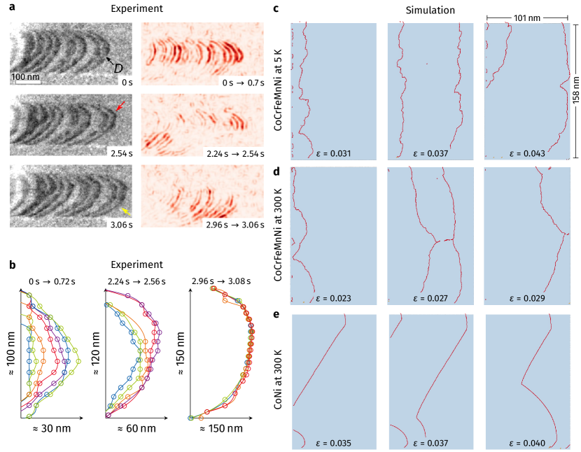
We firstly analyze the structure and glide motion of dislocations in CoCrFeMnNi HEA by in- situ TEM tensile straining (Fig. 1 and Supplementary Movie 1). Uniaxial tensile load is applied to the Cu grid which transfers stress to the TEM lamella prepared by focused ion beam (FIB) lift-out. The loading direction and the viewing direction are \hkl[113] and \hkl[21-1], respectively (Supplementary Fig. S1) and three \hkl111 slip planes are inclined with respect to the viewing direction. Due to the finite thickness of the TEM thin foil, which is around , dislocation glide on the slip planes is constrained by the top and bottom surfaces.
Fig. 1a presents the representative TEM snapshots showing the glide motion of an array of Shockley partial dislocations which are separated by SFs appearing as dark bands. The dislocations bow out under the local resolved shear stress toward their glide direction. All images are processed to enhance the dislocation contrast (see section “Methods”). Tracing the evolution of the dislocation line shape during glide reveals that dislocations move through a kink-pair-like mechanism[45]. For example, only the upper part of the dislocation marked by a red arrow moves forward, then with some delay, the bottom part (yellow arrow) follows. The difference images in the right panel of Fig. 1a , highlighting the relative changes between two frames, show that only certain segments of dislocations move within a given time frame while others remain pinned.
This jerky motion can be seen more clearly by tracing the dislocation position over time (Fig. 1b). The positions are extracted using Gaussian and ridge detection image filters. As described above, a short segment of the dislocation line propagates first by forming a small hump, while the rest hardly moves. Most dislocations exhibit this type of localized pinning-unpinning along their lines constantly during glide, which could be the reason for the high shear stress required for dislocation glide in HEAs[17]. The effects of experimental artifacts, such as FIB damages or surface oxide, are expected to be marginal since these are present at the outer surface of the TEM sample with a small thickness of [46, 47] while the total thin foil thickness is around . Therefore, the jerky motion in the middle of a dislocation, which is placed near the center of the TEM foil should not be affected by these surface artifacts.
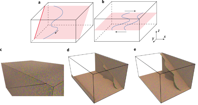
In order to investigate whether the inherently meandering dislocation line shape seen in TEM can be reproduced via atomistic computer simulations, samples of comparable size are built. Each sample contains about 100 million atoms and features an inclined glide plane measuring (shown in Supplementary Figs. S2a,c-d). To facilitate dislocation nucleation under tensile load a surface notch, aligned with this glide plane, is cut into the sample before loading the sample. Figs. 1c-e show the first Shockley partial dislocations emitted and gliding away from this notch under tensile load. At low temperatures (), strong pinning of the dislocation line in the HEA can be seen (Fig 1c). These manifest as “V”-shaped dislocation line arrangements, where the line is pinned in one spot, while neighboring dislocation segments advance. These pinning points occur frequently, which results in a rough dislocation line. Thermal activation at ambient temperature renders dislocations apparently straighter ( Fig. 1d). The thermal energy lifts the dislocation over some of its weaker pinning sites, thus only the strong pinning points, which have a much lower density, persist active. For comparison, dislocations in the binary CoNi alloy were studied in an identical geometry (see Fig. 1e). There are almost no dislocation pinning points in this material, leading to straight dislocation segments during glide. The cusp in the middle of the dislocation stems from the sequence of initial nucleation events at the notch (cf. Supplementary Fig. S2d,e). Thus, the effect of strong dislocation pinning in HEAs and weaker dislocation pinning in binary alloys can be resolved. Moreover, the molecular dynamics (MD) simulations provide clear evidence for intrinsically wavy dislocations in the absence of SRO as observed, experimentally.
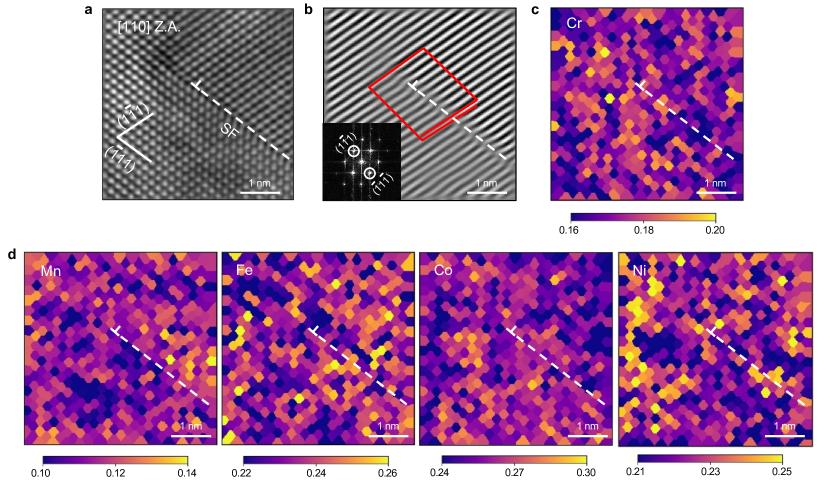
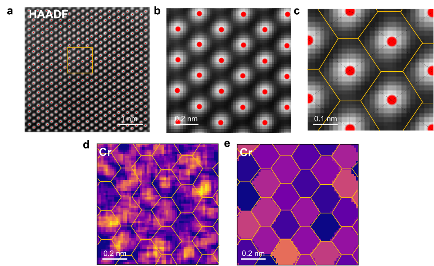
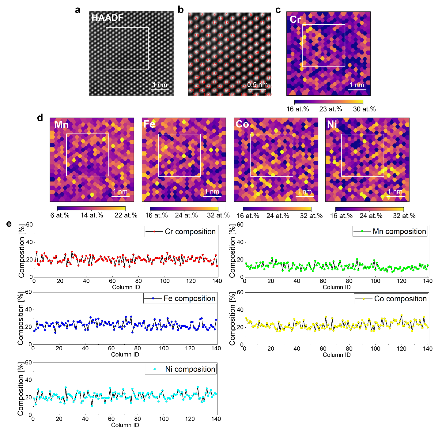
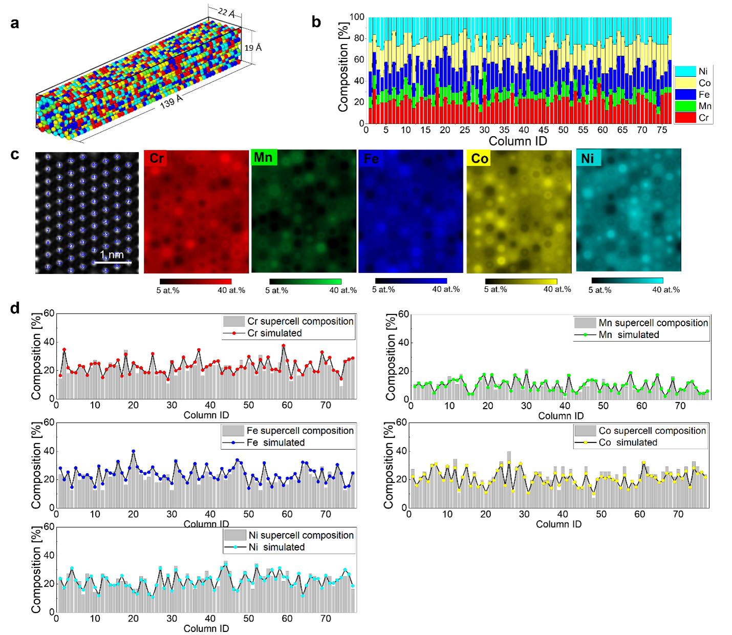
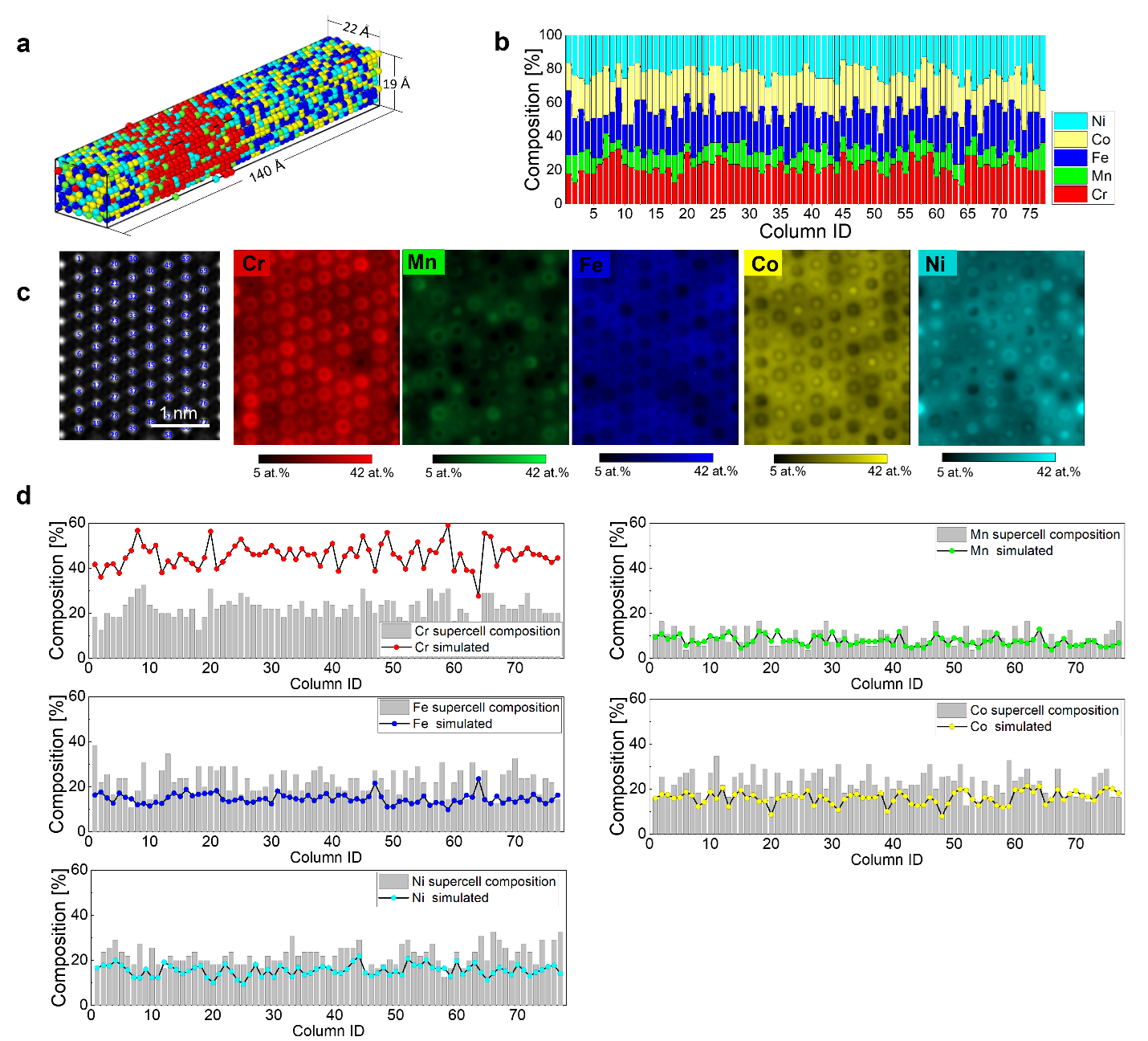
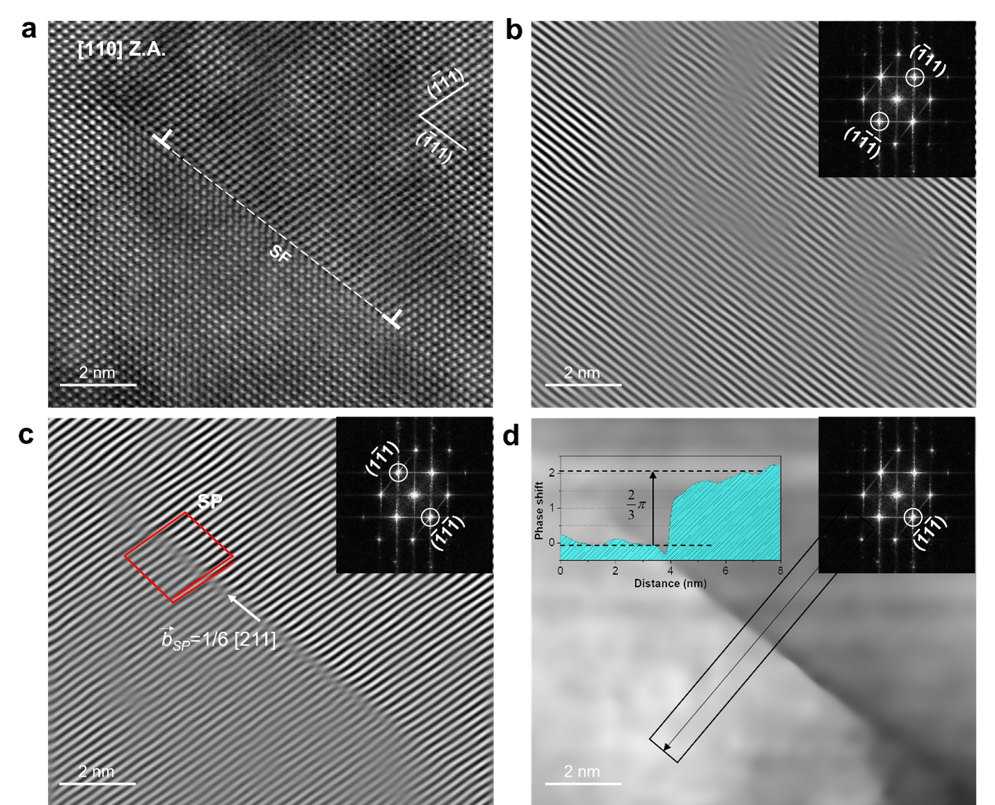
A comparison of experiment and simulation in Fig 1 is only valid if both samples are in a similar random solid solution state. While it is clear from the sample preparation that there is no elemental clustering in the virtual sample, this question has not been answered definitively for the TEM sample. Lee et al.[17] previously performed atom probe tomography measurements on the samples shown in Fig 1a and found no elemental ordering or clustering on the length scale of . For further detailed analysis, we carried out atomic-resolution STEM EDS chemical mapping and quantitative analysis combined with EDS simulations (Supplementary Figs. S3-S6) to determine the concentration of each atomic column around a Shockley partial dislocation. The high-angle annular dark field (HAADF) STEM image of the Shockley partial and its Bragg filtered analysis are given in Fig 2a,b, confirming the Burgers vector of the selected dislocation core, where is the lattice constant. With this quantitative evaluation of composition at each atomic column combined with EDS simulation, we could conclude the chemical homogeneity around the dislocation core without apparent clustering or segregation of specific element(s). There is fluctuation in per-column concentration though, which is, however, in line with the pristine bulk and negligibly small (Supplementary Fig. S4). This result is also consistent with the recent high-resolution EDS experiments by Heczko et al.[48], who report no elemental segregation to the strain field of Shockley partial dislocations in heat-treated Cantor alloy.
3.2 A local descriptor for dislocation pinning in HEAs
Fig. 1 shows an inherent waviness of dislocation lines during glide in both experiment and simulation, indicating the existence of dislocation pinning sites. While we know that the simulated sample is in a perfectly random state without elemental clustering or short-range order, the experiments also show that there is no clustering or segregation around the dislocation core of Shockley partial dislocation.
Therefore, some statistically occurring atomic arrangements must be present, even in the random alloy, which pin the dislocation lines and locally hinder their glide. In the following, we investigate a single (dissociated) edge dislocation in the equimolar CoCrFeMnNi HEA to determine the nature of these nanoscale dislocation pinning points.
The established Peierls model of dislocation glide states that the stress required to move a dislocation is proportional to the maximum gradient along the energy path connecting two adjacent stable dislocation positions. For pure metals, this energy pathway (Peierls energy) may be approximated by a sinusoid and the so-called Peierls stress can be calculated analytically as a derivative of this energy. In dilute solid solutions, the local energy landscape is modified in the vicinity of each solute and therefore the local stresses required for dislocation glide changes[49, 50].
As the exact form of the Peierls energy landscape is usually unknown, the generalized stacking fault (GSF) energy surface[51, 41] is often taken as a stand-in. The GSF energy surface maps the energy required to rigidly displace two densely packed crystal planes against each other. Supplementary Fig. S8 shows the GSF energy surface for a HEA sample. Here, the displacement and energy profiles corresponding to leading and trailing partial are indicated. As the GSF energy profile is obtained by averaging over the whole lattice plane, it is symmetric and smooth, showing no effect of the local chemical inhomogeneity. However, given the strong variance in local chemical arrangements, it is expected that the GSF energy varies on a local scale in HEAs.
It is widely accepted that the stable SF energy in HEAs, which marks a single point on the GSF curve strongly depends on the chemical environment[52, 53]. Therefore, one would expect this dependence also for other points on the GSF landscape. From the locally fluctuating GSF landscape, one can directly conclude that the Peierls stress and thereby resistance against dislocation glide in HEAs becomes a spatially varying quantity. In the following, we will calculate this for each atom in the glide plane.
While the calculation of a local GSF energy landscape seems counterintuitive at first glance, it becomes a rather well-defined problem in the framework of classical atomistic simulations. LAMMPS[32], by relying on interatomic potentials, is not only able to calculate the total energy for an arrangement of atoms but also assign a specific energy contribution to each atom. If we now perform a GSF energy calculation for the HEA system, we can store these per-atom energies and therefore obtain not only the global GSF energy landscape but also one resolved for each atom. While the general idea of this approach is similar to the stochastic Peierls-Nabarro model proposed in Refs. [54, 55], we do not attempt to find a closed form mathematical description of the local Peierls stress but instead measure the atomic Peierls force directly and confirm their effect on the dislocation pinning in a given alloy.
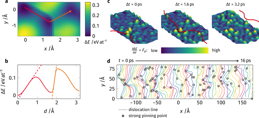
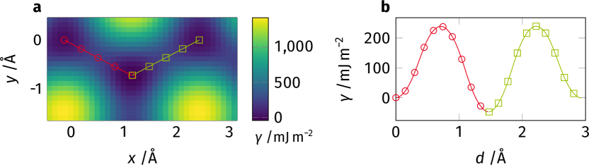
Fig. 3a shows the energy landscape for a single Co atom in the GSF plane. Compared to the globally averaged GSF energy landscape (Supplementary Fig. S8) one can already see that the projected atomic energies are not symmetric anymore, as the local chemical environment changes after the initial displacement (red). Therefore, displacing this Co atom along the leading (red) and trailing (orange) partial dislocation displacement path does not result in the same energy barrier. Fig. 3b shows the corresponding energy profiles along the two displacement paths. Dashed lines indicate the maximum gradient of the GSF curve, which corresponds to the local Peierls friction force. This value is proportional to the strength of this atom acting as a pinning point for the dislocation line and is denoted as . Note, this pinning point’s strength is given in units of force (). It cannot be normalized to stress () as the area per-atom is not well defined in HEAs.
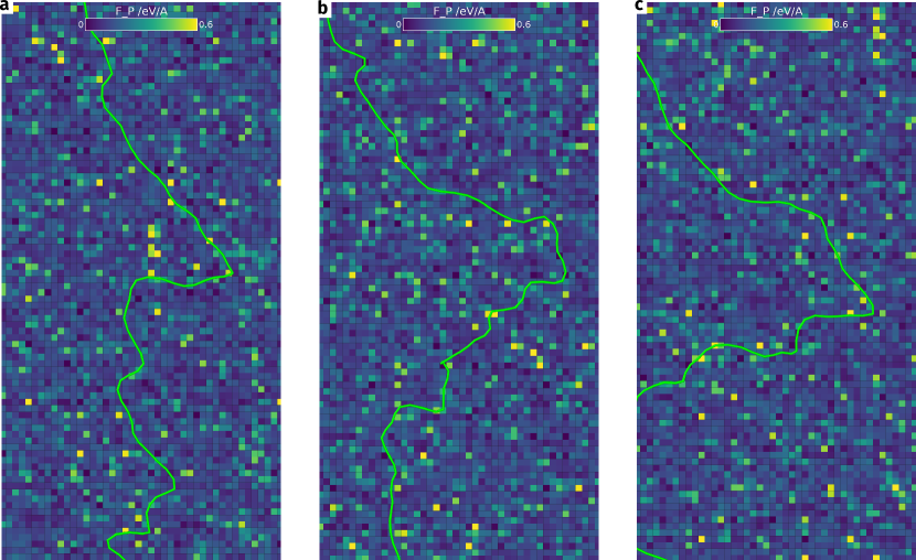
The next question is whether this approach actually works in describing the dislocation pinning on the atomic scale. To answer this, we insert a single edge dislocation into this pre-calculated GSF plane and apply a constant shear load to it. Fig. 3c shows the leading partial dislocation of the dissociated edge dislocation gliding from left to right across the calculated pinning point landscape (the atomic pinning point strength is averaged on a grid and smeared out for better visibility). Movie S2 shows this sequence in motion. Here, the dislocation is pinned on the highest strength pinning point, i.e., the strongest, obstacle and bows out under the applied shear. Once the adjacent dislocation line segments have advanced a sufficient distance, the increase in line tension lifts the dislocation line across this strong obstacle and the dislocation continues its glide. After the dislocation has passed a given area the atoms are shuffled and the dislocation pinning point landscape changes for following dislocations.
Lastly, Fig. 3d shows the extracted position of the leading partial dislocation during glide over a time interval. As the dislocation snapshots are taken every , multiple closely spaced line segments correspond to the positions where the dislocation line is locally pinned while wider line spacing indicates faster dislocation glide. Superimposed are gray circles indicating positions of the highest local pinning point strength predicted from the atomic GSF calculations. Even by eye, a good match between proposed pinning points and regions of strong pinning is discernible. Obviously, there is no simple 1:1 correspondence between dislocation line shape and proposed pinning sites. This is the case as the “history” of the dislocation changes its current behavior. If the dislocation line was initially pinned and is therefore strongly bowed out, there is an additional force arising from the line tension to straighten out the dislocation line and shorten its overall length which can assist the crossing of pinning points along its way.
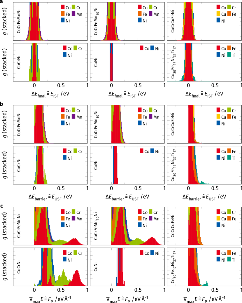
Given that our simulations have found an atomic scale descriptor for dislocation pinning points that is in line with the established theory of the Peierls model, we test this descriptor for a wide range of HEAs and search if an increased number of high lattice sites occurs.
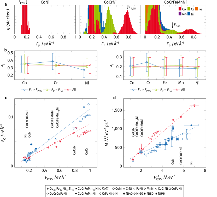
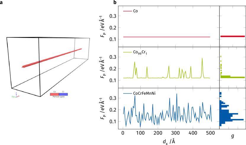
Following the steps outlined in the previous section, we prepare a wide range of samples of different composition ranging from binary and ternary alloys to different HEAs. First, the atomic GSF landscape is calculated for all atoms in a given \hkl111 plane. Fig. 4a shows the calculated distribution for CoNi, CoCrNi, and CoCrFeMnNi. This comparison reveals that in CoNi almost all pinning points have a resistive force below . The addition of Cr leads to a substantial change in this spectrum. The interaction of Co and Cr causes the emergence of a new peak with values where Co atoms have become substantial obstacles for the dislocation line. Some Cr atoms occupy states of intermediate pinning point strength. Subsequent addition of Fe and Mn, on the other hand, does not alter the observed pinning point spectrum much. The strength of the Co and Cr atoms remains unchanged but as their concentration decreases so does the density of strong pinning sites. Both Fe and Mn are only weakly pinning ()elements within this matrix.
The three examples presented in Fig. 4a suggest the Co-Cr interaction to be responsible for strong dislocation pinning points. To confirm, we explore the mean concentration in the first and second nearest neighbor shell of the strongest (95th percentile ) and the weakest (5th percentile ) pinning points. The resulting concentrations, given in Fig. 4b, reveal that the concentration of Cr is increased around the strongest pinning points. Be reminded that the strong pinning points are exclusively Co atoms, confirming the interaction of these two species. The weak pinning points, on the other hand, mirror the bulk concentration (labeled “All”) suggesting that there are distinct atomic environments responsible for the strongest dislocation pinning, even in a random alloy. However, the chemical concentrations of the atomic coordination acting as strong pinning sites show a great variance suggesting that there is not a single atomic arrangement responsible for the dislocation pinning.
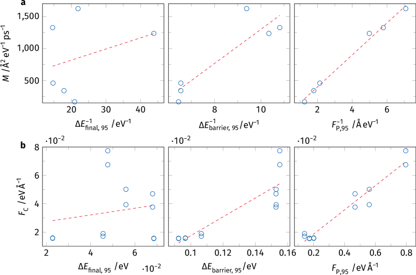
Next, we investigate the effect of the pinning point spectrum on the critical force required to initiate dislocation glide as well as their mobility. One would expect dislocation pinning to be dominated by the fraction of strongest pinning points holding back the dislocation line. Therefore, we take as a descriptor. For reference, this 95th percentile is marked in Fig. 4a. The dislocations in each sample are subjected to increasing shear until they start to glide. The critical applied force to initiate glide, , is determined as the force required to move the dislocation by . These simulations are carried out at cryogenic temperatures to reduce thermal noise on the dislocation line shape. Note that this force is not necessarily identical for leading and trailing partial dislocations, especially for CoCrFeMnNi and CoCrNi which have negative SF energies, resulting in an additional driving force acting on the leading partial. Fig. 4c shows over for all samples. Blue symbols indicate results for the smaller samples with an initial dislocation line length of 20 unit cells, while red symbols indicate results from larger samples with an initial line length of 200 unit cells, i.e., lattice constants . A clear linear relationship between the pinning point density and the critical force can be seen within the small and large sample series confirming the expected correlation, where an increased density of strong pinning points leads to an increased force required to move a dislocation. Note that both sample sets are not on the same line, as the longer dislocation has a higher probability of having a locally weakly pinned segment where glide can start. This segment subsequently drags the other dislocation segments along. The mechanism is comparable to the weakest-link model proposed by Nöhring and Curtin[56] for cross-slip in FCC HEA, as suggested by Rizzardi et al.[57].
We also calculate the dislocation mobility under a constant applied shear (Fig. 4d). Here, each sample is subjected to constant shear equivalent to the critical force required to move the leading partial dislocation by (depending on the sample). In some samples, repeated pinning and depinning of the dislocation line were observed. Here, we isolated segments of constant velocity v and calculated the mobility as, [49], where is the applied shear force. While the critical force was found to be proportional to , the dislocation mobility should be inversely related to this value—the stronger the pinning points are, the slower and less mobile the dislocation will be. Therefore, we plot the extracted dislocation mobilities against . Again, a linear correlation between the dislocation mobility and the pinning point descriptor can be seen within each set of samples. Similar to the critical force, the weakest-link argument can be taken as an explanation for the differences between the two differently sized samples. Recent work by Sills et al.[58] showed a similar effect in stainless steels, where very long dislocation line lengths were required to converge the calculated dislocation mobility. However, comparing samples of identical initial dislocation line lengths should be valid.
To confirm that the correlations shown here are no coincidence, we also compare and against other descriptors derived from the per-atom GSF curves. These can be found in Supplementary Figs. S12 and S13. Here we show the atomic stable and unstable stacking fault energies to , plotting their distribution following Fig. 4a and the resulting correlations akin to Figs. 4c,d. This confirms that is by far the best descriptor for and .
In summary, we show that the dislocation pinning points identified in the Cantor alloy could also be found in different binary and ternary alloys. The critical force required for a dislocation to move correlates with the density of high strength pinning points identified from the atomic scale resolved GSF curves. Similarly, a greater number of strong pinning sites leads to overall reduced dislocation mobility in all investigated samples, independent of the material system or interatomic potential used. Investigation of the chemical environment around each pinning point reveals Co at its center and an increase in Cr in its surrounding, however, no single structural motif responsible for dislocation pinning has been confirmed. Given that the interaction of Co and Cr atoms needs to be harnessed, direct adjacency seems to be preferable.
4 Discussion
4.1 Impact of the dislocation pinning points
We propose a descriptor for dislocation pinning sites in concentrated alloys. The descriptor is physically motivated and based on the atomic Peierls friction, which can be calculated as the maximum gradient of the per-atom GSF energy. We calculate the descriptor for a given pristine lattice plane, which is subsequently traversed by a dislocation allowing for direct spatial correlation of the established descriptor and observed dislocation pinning sites. Concentration analysis of the strongest dislocation pinning points reveals that they stem from the unique, nonlinear, interaction of Co and Cr atoms.
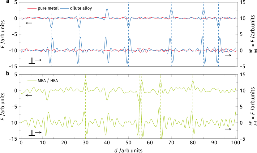
The energy and force landscape felt by a dislocation is schematically shown in Fig. 5. In a pure metal, the energy change encountered by a dislocation during glide is negligibly small. Therefore, the gradient of this energy and hence the force required to move the dislocation is almost zero as well[59]. If a low concentration of solutes is added to the metal, forming a dilute solid solution, these solutes can either form local energy minima that trap the dislocation or high energy barriers blocking dislocation advancement. Both effects lead to steep energy gradients and therefore require high forces to be passed (Fig. 5a). In a concentrated HEA (Fig. 5b), on the other hand, the energy variance in the matrix is already higher hindering dislocation glide. However, as shown in Figs. 3 and 4, there are some environments that pin dislocations exceptionally strongly. These could stem from atomic arrangements where an energy minimum is located next to a barrier (as shown around in Fig. 5b), leading to a steeper energy gradient. While these arrangements are theoretically also possible in dilute alloys, their probability is much lower given the lower density of secondary atoms. To confirm this schematic image, we also prepared linear profiles of the landscape in Co, Co99Cr1, and CoCrFeMnNi samples. These are shown in Supplementary Fig. S11 and confirm that there are no strong pinning points in the pure metal, some discrete strong pinning sites in the dilute CoCr solid solution and an abundance of pinning spots in the full HEA. The strong pinning spots in the CoCrFeMnNi alloy do not only show an increase in frequency but also higher peak values.
The identification of dislocation pinning points allows us to sample their density for different binary and ternary alloys and compare those to the CoCrFeMnNi HEA. As shown in Fig. 4a, neither Co nor Cr alone leads to a substantial shift in the distribution when added to Ni. Only the addition of both gives rise to a pronounced increase in pinning point density and strength. Further addition of Fe and Mn leads to no relevant changes in the spectrum and therefore only decreases the density of strong pinning points. The intuitive trends expected from the densities of strong pinning points, i.e., increasing resistance against dislocation glide and reduced mobility as the fraction of strong pinning points in a material increases are confirmed by our single dislocation shear simulations. Even though this is by no means a solid solution strengthening model, one might naively assume that an increased resistance against the onset of dislocation glide corresponds to an increase in the strength of a material. Under this assumption, our findings would be in line with experimental observations, where CoCrNi consistently shows higher hardness[60] and tensile yield strength[2, 61] compared to other alloys from the same family, including the component CoCrFeMnNi Cantor alloy. Additional simulations show that Ni is not even a necessary constituent, as a FCC random solid solution of CoCr has an even higher dislocation pinning than CoCrNi. This is in agreement with established literature, where FCC Co63Cr29 alloys are commonly used in dental prosthetics due to their high yield strength and work hardening[62].
Li et al.[7] reported the strengthening in regions of increased Co-Cr bonding by calculating the activation energy for dislocation motion in samples with different degrees of Co-Cr local ordering. Their calculation method requires the use of dedicated smaller samples, which means that they cannot calculate the energy barrier for long-range dislocation glide. Our approach, on the other hand, allows the determination of the atomic pinning point strength in the glide plane of the dislocation. Therefore, a direct spatial correlation between the atomic descriptor and pinned dislocation line can be made. Antillon et al.[63] also proposed a method of calculating the local energy barrier against dislocation glide. Their method, however, relies on energy measurements as the dislocation passes through the material in a MD simulation. In contrast, the proposed descriptor can be calculated from the pristine material, i.e., without an embedded dislocation, under static conditions. Therefore, this descriptor has the possibility of being used for future materials design, as it does not require costly MD simulations of many hundred-thousands of atoms to identify potential chemical compositions of strong dislocation pinning.
4.2 Transferability of our results
The simulation results outlined in this manuscript were all obtained at cryogenic temperatures. This suppresses the thermally assisted passing of dislocation pinning points. Within the framework of transition-state theory, the energy barrier (not the pinning forces considered in Figs. 3 and 4) associated with a pinning point becomes important to determine whether a dislocation is pinned on a given pinning site. Therefore, the pinning points found here will only pin a dislocation, if the applied force is below the pinning point strength and the associated energy barrier is greater than the thermal energy. Assuming that the energy landscape is unchanged by both temperature and the presence of the dislocation, we can take the per-atom unstable stacking fault energy as a surrogate for the local energy barrier. Considering our data, we can see that the unstable stacking fault energy shows broad distributions in these alloys: CoNi , CoCrNi , and CoCrFeMnNi , with overall relatively low energy barriers suggesting that thermal activation will become important at intermediate temperatures.
We propose that the dissociated edge dislocation studied here is representative of FCC materials. In general, the calculated values are intrinsically insensitive to the dislocation character, as they are calculated based on the pristine lattice. This also extends to the actual pinning point-dislocation interaction. Our descriptor only accounts for the rigid displacement of the atoms during the passage of the dislocation. This means that even though the shear direction (in relation to the line direction) is different for screw and edge dislocations, the shear process is comparable. Hence, there is no obvious dependence of our descriptor on the dislocation character. However, the displacement paths that need to be calculated to obtain depends on the shear direction, i.e., the Burgers vector. This is an obvious difference from established solid solution strengthening models, e.g., Ref.[21], where the elastic interaction between solute and dislocation depends on their stress fields and therefore on the dislocation character. Based on these arguments, we also expect the coupling of Co and Cr, shown in Fig. 4b, to be independent of the dislocation character.
Dislocations in body-centered cubic (BCC) metals glide differently than dislocations in FCC metals. Usually, the Peierls barrier in BCC metals is much higher requiring a kink-pair mechanism to advance the dislocation[49]. Based on this mechanism, the displacement of the atoms is most likely different from the rigid shear displacements covered by our descriptor. Therefore, it is most likely not directly applicable. However, if one finds the rigid shear “path” or trajectories of the atoms involved in such a process in the BCC matrix, the resulting force barriers could be calculated in a similar way. The glide of screw dislocations through a BCC HEA matrix has recently been studied in detail by Wang et al.[64], who use nudged elastic band calculations to understand the energy landscape of the gliding dislocation through the BCC matrix.
Our study reveals the atomic origin of dislocation pinning points in multi-principal element alloys thereby answering a long-standing question in the materials science and engineering community. We find that no distinct SRO is required for strong dislocation pinning in HEAs as local pinning of the dislocation line is facilitated by a locally increased slope of the GSF curve. This scenario agrees with the established Peierls model but reveals that HEA and specific alloys are susceptible to exceptional Peierls peak heights. In the alloy samples investigated, these changes are highly non-linear and the interaction of Co and Cr leads to the highest density of strong dislocation pinning points. This understanding of the local Peierls stress landscape and the resulting pinning forces acting on dislocations gives access to a different parameter that can be tuned in the design of alloys with increased resistance against the onset of dislocation glide and overall reduced dislocation mobility.
Acknowledgements
The authors would like to acknowledge financial support by the Deutsche Forschungs Gemeinschaft (DFG) under Grant Nos. AL 578/25-2, and DE 796/13-1 as part of SPP 2006. S.L. is funded by Alexander von Humboldt Foundation. S.H.O. was supported by the KENTECH Research Grant (KRG2022-01-019), National Research Foundation of Korea (NRF) grant funded by the Korean government (MSIT) (NRF-2020R1A2C2101735), Creative Materials Discovery Program (NRF-2015M3D1A1070672, NRF-2019M3D1A1078296), Bioinspired Innovation Technology Development Project (NRF-2018M3C1B7021994). Calculations for this research were conducted on the Lichtenberg high-performance computer of the TU Darmstadt. The authors gratefully acknowledge the Gauss Centre for Supercomputing e.V. (www.gauss-centre.eu) for funding this project by providing computing time on the GCS Supercomputer SuperMUC-NG at Leibniz Supercomputing Centre (www.lrz.de). Author contributions S.H.O., G.D., and K.A. conceived the research. D.U. and A.S. carried out and analyzed the computational simulations. S.L. carried out in situ TEM experiment and the analysis of TEM data. H.J. and Y.X. conducted STEM EDS experiments and analysis. The first draft of the paper was written by D.U. and S.L., and all authors contributed with comments and edits.
References
- George et al. [2019] Easo P. George, Dierk Raabe, and Robert O. Ritchie. High-entropy alloys. Nature Reviews Materials, 4(8):515–534, 2019. ISSN 2058-8437. doi:10.1038/s41578-019-0121-4.
- Wu et al. [2014a] Z. Wu, H. Bei, G.M. Pharr, and E.P. George. Temperature dependence of the mechanical properties of equiatomic solid solution alloys with face-centered cubic crystal structures. Acta Materialia, 81:428–441, 2014a. ISSN 13596454. doi:10.1016/j.actamat.2014.08.026.
- Gludovatz et al. [2014] B. Gludovatz, A. Hohenwarter, D. Catoor, E. H. Chang, E. P. George, and R. O. Ritchie. A fracture-resistant high-entropy alloy for cryogenic applications. Science, 345(6201):1153–1158, 2014. ISSN 0036-8075, 1095-9203. doi:10.1126/science.1254581.
- Li et al. [2016] Zhiming Li, Konda Gokuldoss Pradeep, Yun Deng, Dierk Raabe, and Cemal Cem Tasan. Metastable high-entropy dual-phase alloys overcome the strength–ductility trade-off. Nature, 534(7606):227–230, 2016. ISSN 1476-4687. doi:10.1038/nature17981.
- George et al. [2020] E. P. George, W. A. Curtin, and C. C. Tasan. High entropy alloys: A focused review of mechanical properties and deformation mechanisms. Acta Materialia, 188:435–474, 2020. ISSN 13596454. doi:10.1016/j.actamat.2019.12.015.
- Raabe et al. [2015] Dierk Raabe, Cemal Cem Tasan, Hauke Springer, and Michael Bausch. From High-Entropy Alloys to High-Entropy Steels. steel research international, 86(10):1127–1138, 2015. ISSN 16113683. doi:10.1002/srin.201500133.
- Li et al. [2019] Qing-Jie Li, Howard Sheng, and Evan Ma. Strengthening in multi-principal element alloys with local-chemical-order roughened dislocation pathways. Nature Communications, 10(1):3563, 2019. ISSN 2041-1723. doi:10.1038/s41467-019-11464-7.
- Yin et al. [2020] Binglun Yin, Shuhei Yoshida, Nobuhiro Tsuji, and W. A. Curtin. Yield strength and misfit volumes of NiCoCr and implications for short-range-order. Nature Communications, 11(1):2507, 2020. ISSN 2041-1723. doi:10.1038/s41467-020-16083-1.
- Zhang et al. [2020] Ruopeng Zhang, Shiteng Zhao, Jun Ding, Yan Chong, Tao Jia, Colin Ophus, Mark Asta, Robert O. Ritchie, and Andrew M. Minor. Short-range order and its impact on the CrCoNi medium-entropy alloy. Nature, 581(7808):283–287, 2020. ISSN 0028-0836, 1476-4687. doi:10.1038/s41586-020-2275-z.
- Nöhring and Curtin [2020] W.G. Nöhring and W.A. Curtin. Design using randomness: A new dimension for metallurgy. Scripta Materialia, 187:210–215, 2020. ISSN 13596462. doi:10.1016/j.scriptamat.2020.06.012.
- Ma [2020] Evan Ma. Unusual dislocation behavior in high-entropy alloys. Scripta Materialia, 181:127–133, 2020. ISSN 13596462. doi:10.1016/j.scriptamat.2020.02.021.
- Gerold and Karnthaler [1989] V. Gerold and H.P. Karnthaler. On the origin of planar slip in f.c.c. alloys. Acta Metallurgica, 37(8):2177–2183, 1989. ISSN 00016160. doi:10.1016/0001-6160(89)90143-0.
- Antillon et al. [2020] E. Antillon, C. Woodward, S.I. Rao, B. Akdim, and T.A. Parthasarathy. Chemical short range order strengthening in a model FCC high entropy alloy. Acta Materialia, 190:29–42, 2020. ISSN 13596454. doi:10.1016/j.actamat.2020.02.041.
- Otto et al. [2013] F. Otto, A. Dlouhý, Ch. Somsen, H. Bei, G. Eggeler, and E.P. George. The influences of temperature and microstructure on the tensile properties of a CoCrFeMnNi high-entropy alloy. Acta Materialia, 61(15):5743–5755, 2013. ISSN 13596454. doi:10.1016/j.actamat.2013.06.018.
- Zeng et al. [2019] Yifei Zeng, Xiaorong Cai, and Marisol Koslowski. Effects of the stacking fault energy fluctuations on the strengthening of alloys. Acta Materialia, 164:1–11, 2019. ISSN 13596454. doi:10.1016/j.actamat.2018.09.066.
- Smith et al. [2016] T.M. Smith, M.S. Hooshmand, B.D. Esser, F. Otto, D.W. McComb, E.P. George, M. Ghazisaeidi, and M.J. Mills. Atomic-scale characterization and modeling of 60° dislocations in a high-entropy alloy. Acta Materialia, 110:352–363, 2016. ISSN 13596454. doi:10.1016/j.actamat.2016.03.045.
- Lee et al. [2020] Subin Lee, María Jazmin Duarte, Michael Feuerbacher, Rafael Soler, Christoph Kirchlechner, Christian H. Liebscher, Sang Ho Oh, and Gerhard Dehm. Dislocation plasticity in FeCoCrMnNi high-entropy alloy: Quantitative insights from in situ transmission electron microscopy deformation. Materials Research Letters, 8(6):216–224, 2020. ISSN 2166-3831. doi:10.1080/21663831.2020.1741469.
- Laplanche et al. [2016] G. Laplanche, A. Kostka, O.M. Horst, G. Eggeler, and E.P. George. Microstructure evolution and critical stress for twinning in the CrMnFeCoNi high-entropy alloy. Acta Materialia, 118:152–163, 2016. ISSN 13596454. doi:10.1016/j.actamat.2016.07.038.
- Rao et al. [2017] S.I. Rao, C. Woodward, T.A. Parthasarathy, and O. Senkov. Atomistic simulations of dislocation behavior in a model FCC multicomponent concentrated solid solution alloy. Acta Materialia, 134:188–194, 2017. ISSN 13596454. doi:10.1016/j.actamat.2017.05.071.
- Pasianot and Farkas [2020] Roberto Pasianot and Diana Farkas. Atomistic modeling of dislocations in a random quinary high-entropy alloy. Computational Materials Science, 173:109366, 2020. ISSN 09270256. doi:10.1016/j.commatsci.2019.109366.
- Varvenne et al. [2016] Céline Varvenne, Aitor Luque, and William A. Curtin. Theory of strengthening in fcc high entropy alloys. Acta Materialia, 118:164–176, 2016. ISSN 13596454. doi:10.1016/j.actamat.2016.07.040.
- Labusch [1970] R. Labusch. A Statistical Theory of Solid Solution Hardening. physica status solidi (b), 41(2):659–669, 1970. ISSN 03701972, 15213951. doi:10.1002/pssb.19700410221.
- Fleischer [1963] R.L Fleischer. Substitutional solution hardening. Acta Metallurgica, 11(3):203–209, 1963. ISSN 00016160. doi:10.1016/0001-6160(63)90213-X.
- Raghavan et al. [2017] R. Raghavan, C. Kirchlechner, B.N. Jaya, M. Feuerbacher, and G. Dehm. Mechanical size effects in a single crystalline equiatomic FeCrCoMnNi high entropy alloy. Scripta Materialia, 129:52–55, 2017. ISSN 13596462. doi:10.1016/j.scriptamat.2016.10.026.
- Li et al. [2018] Chen Li, Gerlinde Habler, Lisa C. Baldwin, and Rainer Abart. An improved FIB sample preparation technique for site-specific plan-view specimens: A new cutting geometry. Ultramicroscopy, 184:310–317, 2018. ISSN 03043991. doi:10.1016/j.ultramic.2017.09.011.
- Lee and Baskes [2000] Byeong-Joo Lee and M. I. Baskes. Second nearest-neighbor modified embedded-atom-method potential. Physical Review B, 62(13):8564–8567, 2000. ISSN 0163-1829, 1095-3795. doi:10.1103/PhysRevB.62.8564.
- Choi et al. [2018] Won-Mi Choi, Yong Hee Jo, Seok Su Sohn, Sunghak Lee, and Byeong-Joo Lee. Understanding the physical metallurgy of the CoCrFeMnNi high-entropy alloy: An atomistic simulation study. npj Computational Materials, 4(1):1, 2018. ISSN 2057-3960. doi:10.1038/s41524-017-0060-9.
- Farkas and Caro [2018] Diana Farkas and Alfredo Caro. Model interatomic potentials and lattice strain in a high-entropy alloy. Journal of Materials Research, 33(19):3218–3225, 2018. ISSN 0884-2914, 2044-5326. doi:10.1557/jmr.2018.245.
- Zhou et al. [2004] X. W. Zhou, R. A. Johnson, and H. N. G. Wadley. Misfit-energy-increasing dislocations in vapor-deposited CoFe/NiFe multilayers. Physical Review B, 69(14):144113, 2004. ISSN 1098-0121, 1550-235X. doi:10.1103/PhysRevB.69.144113.
- Daw and Baskes [1983] Murray S. Daw and M. I. Baskes. Semiempirical, Quantum Mechanical Calculation of Hydrogen Embrittlement in Metals. Physical Review Letters, 50(17):1285–1288, 1983. ISSN 0031-9007. doi:10.1103/PhysRevLett.50.1285.
- Daw and Baskes [1984] Murray S. Daw and M. I. Baskes. Embedded-atom method: Derivation and application to impurities, surfaces, and other defects in metals. Physical Review B, 29(12):6443–6453, 1984. ISSN 0163-1829. doi:10.1103/PhysRevB.29.6443.
- Thompson et al. [2022] Aidan P. Thompson, H. Metin Aktulga, Richard Berger, Dan S. Bolintineanu, W. Michael Brown, Paul S. Crozier, Pieter J. in ’t Veld, Axel Kohlmeyer, Stan G. Moore, Trung Dac Nguyen, Ray Shan, Mark J. Stevens, Julien Tranchida, Christian Trott, and Steven J. Plimpton. LAMMPS - a flexible simulation tool for particle-based materials modeling at the atomic, meso, and continuum scales. Computer Physics Communications, 271:108171, 2022. ISSN 00104655. doi:10.1016/j.cpc.2021.108171.
- Hirel [2015] Pierre Hirel. Atomsk: A tool for manipulating and converting atomic data files. Computer Physics Communications, 197:212–219, 2015. ISSN 00104655. doi:10.1016/j.cpc.2015.07.012.
- Stukowski [2010] Alexander Stukowski. Visualization and analysis of atomistic simulation data with OVITO–the Open Visualization Tool. Modelling and Simulation in Materials Science and Engineering, 18(1):015012, 2010. ISSN 0965-0393, 1361-651X. doi:10.1088/0965-0393/18/1/015012.
- Tange [2011] O. Tange. GNU parallel - the command-line power tool. ;login: The USENIX Magazine, 36(1):42–47, 2011. doi:http://dx.doi.org/10.5281/zenodo.16303.
- Brandl et al. [2009] Christian Brandl, Peter M. Derlet, and Helena Van Swygenhoven. Strain rates in molecular dynamics simulations of nanocrystalline metals. Philosophical Magazine, 89(34-36):3465–3475, 2009. ISSN 1478-6435, 1478-6443. doi:10.1080/14786430903313690.
- Stukowski and Albe [2010] Alexander Stukowski and Karsten Albe. Extracting dislocations and non-dislocation crystal defects from atomistic simulation data. Modelling and Simulation in Materials Science and Engineering, 18(8):085001, 2010. ISSN 0965-0393, 1361-651X. doi:10.1088/0965-0393/18/8/085001.
- Stukowski et al. [2012] Alexander Stukowski, Vasily V Bulatov, and Athanasios Arsenlis. Automated identification and indexing of dislocations in crystal interfaces. Modelling and Simulation in Materials Science and Engineering, 20(8):085007, 2012. ISSN 0965-0393, 1361-651X. doi:10.1088/0965-0393/20/8/085007.
- Osetsky and Bacon [2003] Yu N Osetsky and D J Bacon. An atomic-level model for studying the dynamics of edge dislocations in metals. Modelling and Simulation in Materials Science and Engineering, 11(4):427–446, 2003. ISSN 0965-0393, 1361-651X. doi:10.1088/0965-0393/11/4/302.
- Schneider and Stoll [1978] T. Schneider and E. Stoll. Molecular-dynamics study of a three-dimensional one-component model for distortive phase transitions. Physical Review B, 17(3):1302–1322, 1978. ISSN 0163-1829. doi:10.1103/PhysRevB.17.1302.
- Vítek [1968] V. Vítek. Intrinsic stacking faults in body-centred cubic crystals. Philosophical Magazine, 18(154):773–786, 1968. ISSN 0031-8086. doi:10.1080/14786436808227500.
- Zimmerman et al. [2000] Jonathan A Zimmerman, Huajian Gao, and Farid F Abraham. Generalized stacking fault energies for embedded atom FCC metals. Modelling and Simulation in Materials Science and Engineering, 8(2):103–115, 2000. ISSN 0965-0393, 1361-651X. doi:10.1088/0965-0393/8/2/302.
- Guénolé et al. [2020] Julien Guénolé, Wolfram G. Nöhring, Aviral Vaid, Frédéric Houllé, Zhuocheng Xie, Aruna Prakash, and Erik Bitzek. Assessment and optimization of the fast inertial relaxation engine (fire) for energy minimization in atomistic simulations and its implementation in lammps. Computational Materials Science, 175:109584, 2020. ISSN 09270256. doi:10.1016/j.commatsci.2020.109584.
- Virtanen et al. [2020] Pauli Virtanen, Ralf Gommers, Travis E. Oliphant, Matt Haberland, Tyler Reddy, David Cournapeau, Evgeni Burovski, Pearu Peterson, Warren Weckesser, Jonathan Bright, Stéfan J. van der Walt, Matthew Brett, Joshua Wilson, K. Jarrod Millman, Nikolay Mayorov, Andrew R. J. Nelson, Eric Jones, Robert Kern, Eric Larson, C. J. Carey, İlhan Polat, Yu Feng, Eric W. Moore, Jake VanderPlas, Denis Laxalde, Josef Perktold, Robert Cimrman, Ian Henriksen, E. A. Quintero, Charles R. Harris, Anne M. Archibald, Antônio H. Ribeiro, Fabian Pedregosa, and Paul van Mulbregt. SciPy 1.0: Fundamental algorithms for scientific computing in Python. Nature Methods, 17(3):261–272, 2020. ISSN 1548-7105. doi:10.1038/s41592-019-0686-2.
- Caillard and Martin [2003] Daniel Caillard and Jean-Luc Martin. Thermally Activated Mechanisms in Crystal Plasticity. Pergamon, Amsterdam; Boston, Mass., 2003. ISBN 978-0-08-042703-4 978-0-08-054278-2.
- Kiener et al. [2007] D. Kiener, C. Motz, M. Rester, M. Jenko, and G. Dehm. FIB damage of Cu and possible consequences for miniaturized mechanical tests. Materials Science and Engineering: A, 459(1-2):262–272, 2007. ISSN 09215093. doi:10.1016/j.msea.2007.01.046.
- Mayer et al. [2007] Joachim Mayer, Lucille A. Giannuzzi, Takeo Kamino, and Joseph Michael. TEM Sample Preparation and FIB-Induced Damage. MRS Bulletin, 32(5):400–407, 2007. ISSN 0883-7694, 1938-1425. doi:10.1557/mrs2007.63.
- Heczko et al. [2021] Milan Heczko, Veronika Mazánová, Roman Gröger, Tomáš Záležák, Mohammad S. Hooshmand, Easo P. George, Michael J. Mills, and Antonín Dlouhý. Elemental segregation to lattice defects in the CrMnFeCoNi high-entropy alloy during high temperature exposures. Acta Materialia, page 116719, 2021. ISSN 13596454. doi:10.1016/j.actamat.2021.116719.
- Hirth and Lothe [1982] John Price Hirth and Jens Lothe. Theory of Dislocations. Wiley, New York, 2nd ed edition, 1982. ISBN 978-0-471-09125-7.
- Bulatov and Cai [2006] Vasily V. Bulatov and Wei Cai. Computer Simulations of Dislocations. Number 3 in Oxford Series on Materials Modelling. Oxford University Press, Oxford ; New York, 2006. ISBN 978-0-19-852614-8.
- Lu et al. [2000] Gang Lu, Nicholas Kioussis, Vasily V. Bulatov, and Efthimios Kaxiras. Generalized-stacking-fault energy surface and dislocation properties of aluminum. Physical Review B, 62(5):3099–3108, 2000. ISSN 0163-1829, 1095-3795. doi:10.1103/PhysRevB.62.3099.
- Ding et al. [2018] Jun Ding, Qin Yu, Mark Asta, and Robert O. Ritchie. Tunable stacking fault energies by tailoring local chemical order in CrCoNi medium-entropy alloys. Proceedings of the National Academy of Sciences, 115(36):8919–8924, 2018. ISSN 0027-8424, 1091-6490. doi:10.1073/pnas.1808660115.
- Ikeda et al. [2018] Yuji Ikeda, Fritz Körmann, Isao Tanaka, and Jörg Neugebauer. Impact of Chemical Fluctuations on Stacking Fault Energies of CrCoNi and CrMnFeCoNi High Entropy Alloys from First Principles. Entropy, 20(9):655, 2018. doi:10.3390/e20090655.
- Zhang et al. [2019] Luchan Zhang, Yang Xiang, Jian Han, and David J. Srolovitz. The effect of randomness on the strength of high-entropy alloys. Acta Materialia, 166:424–434, 2019. ISSN 13596454. doi:10.1016/j.actamat.2018.12.032.
- Jiang et al. [2020] Tianpeng Jiang, Yang Xiang, and Luchan Zhang. Stochastic Peierls-Nabarro Model for Dislocations in High Entropy Alloys. arXiv:2004.09375 [cond-mat], 2020.
- Nöhring and Curtin [2018] Wolfram Georg Nöhring and W.A. Curtin. Cross-slip of long dislocations in FCC solid solutions. Acta Materialia, 158:95–117, 2018. ISSN 13596454. doi:10.1016/j.actamat.2018.05.027.
- Rizzardi et al. [2018] Q. Rizzardi, G. Sparks, and R. Maaß. Fast Slip Velocity in a High-Entropy Alloy. JOM, 70(7):1088–1093, 2018. ISSN 1047-4838, 1543-1851. doi:10.1007/s11837-018-2856-6.
- Sills et al. [2020] Ryan B. Sills, Michael E. Foster, and Xiaowang W. Zhou. Line-length-dependent dislocation mobilities in an FCC stainless steel alloy. International Journal of Plasticity, 135:102791, 2020. ISSN 07496419. doi:10.1016/j.ijplas.2020.102791.
- Gilman [2007] J. J Gilman. The “Peierls stress” for pure metals (evidence that it is negligible). Philosophical Magazine, 87(35):5601–5606, 2007. ISSN 1478-6435, 1478-6443. doi:10.1080/14786430701678922.
- Wu et al. [2014b] Z. Wu, H. Bei, F. Otto, G.M. Pharr, and E.P. George. Recovery, recrystallization, grain growth and phase stability of a family of FCC-structured multi-component equiatomic solid solution alloys. Intermetallics, 46:131–140, 2014b. ISSN 09669795. doi:10.1016/j.intermet.2013.10.024.
- Slone et al. [2019] C.E. Slone, J. Miao, E.P. George, and M.J. Mills. Achieving ultra-high strength and ductility in equiatomic CrCoNi with partially recrystallized microstructures. Acta Materialia, 165:496–507, 2019. ISSN 13596454. doi:10.1016/j.actamat.2018.12.015.
- Al Jabbari [2014] Youssef S. Al Jabbari. Physico-mechanical properties and prosthodontic applications of Co-Cr dental alloys: A review of the literature. The Journal of Advanced Prosthodontics, 6(2):138, 2014. ISSN 2005-7806, 2005-7814. doi:10.4047/jap.2014.6.2.138.
- Antillon et al. [2019] E. Antillon, C. Woodward, S.I. Rao, B. Akdim, and T.A. Parthasarathy. A molecular dynamics technique for determining energy landscapes as a dislocation percolates through a field of solutes. Acta Materialia, 166:658–676, 2019. ISSN 13596454. doi:10.1016/j.actamat.2018.12.037.
- Wang et al. [2022] Xinyi Wang, Francesco Maresca, and Penghui Cao. The hierarchical energy landscape of screw dislocation motion in refractory high-entropy alloys. Acta Materialia, 234:118022, 2022. ISSN 13596454. doi:10.1016/j.actamat.2022.118022.
Supplementary Figures
5 Supplementary Methods
Step by step instructions to calculate the per-atom GSF curves
-
•
Prerequisites:
-
–
Establish the equilibrium lattice constant of desired composition at .
-
–
-
•
Sample preparation:
-
–
111 plane aligned with one of the cartesian directions (in our case -axis)
-
–
All atoms on ideal FCC lattice sites with the equilibrium lattice spacing
-
–
Alloy composition and atomic ordering as desired
-
–
-
•
Simulation setup:
-
–
Define 2 groups of atoms one above and one below the GSF \hkl111 plane
-
–
Periodic boundary conditions in the GSF plane, open boundaries normal to the GSF plane
-
–
-
•
Simulation:
-
–
Scan atoms of group 1 across group 2, i.e., displace them in - and -direction (assuming the -direction is \hkl111 aligned). The scan direction / area depends on the Burges vector on the dislocation of interest.
-
–
Relax the system at each displacement grid point and calculate the energy. For relaxation, the forces in - and - direction (in the GSF plane) are set to 0, while the forces in -direction (normal to the GSF plane) are averaged across all atoms in each group, respectively. This results in a rigid body displacement of the two regions (above and below the GSF plane) against each other.
-
–
Store the energy after each minimization (at each grid point) for each atom.
-
–
-
•
Post processing:
-
–
Collect the displacement-energy maps for each atom in the GSF plane
-
–
Apply interpolation using, e.g., bicubic splining
-
–
Find the local minima (cf. Fig. 3) corresponding to the (meta-)stable lattice positions and connect them using straight lines.
-
–
Extract maximum gradients along these profiles
-
–