Photorefractive effect in LiNbO3-based integrated-optical circuits for continuous variable experiments
Abstract
We investigate the impact of photorefractive effect on lithium niobate integrated quantum photonic circuits dedicated to continuous variable on-chip experiments. The circuit main building blocks, i.e. cavities, directional couplers, and periodically poled nonlinear waveguides are studied. This work demonstrates that, even when the effect of photorefractivity is weaker than spatial mode hopping, they might compromise the success of on-chip quantum photonics experiments. We describe in detail the characterization methods leading to the identification of this possible issue. We also study to which extent device heating represents a viable solution to counter this effect. We focus on photorefractive effect induced by light at 775 nm, in the context of the generation of non-classical light at 1550 nm telecom wavelength.
I Introduction
With the development of quantum information technologies, photonic circuits are attracting an increasing interest as platforms for future out-of-laboratory realizations. Strong light confinement in waveguides guarantees efficient quantum state generation and manipulation in miniaturized structures which enables a progressive increase in architecture complexity thanks to high system stability and scalability O’Brien et al. (2009); Tanzilli et al. (2012).
Lithium niobate (LiNbO3) waveguides are particularly well adapted to quantum photonics, featuring easy in- and out-coupling to single-mode fibers, high nonlinear frequency conversion efficiencies, electro-optical properties, and low propagation losses Alibart et al. (2016). Largely used in single photon regime, LiNbO3 chips are now moving also toward applications to continuous variable (CV) quantum optics, where quantum information is coded on light continuous spectrum observables.
CV quantum states produced at telecom wavelengths (around 1550 nm) for quantum communication and computing Andersen et al. (2010) can be deterministically produced in LiNbO3 by spontaneous parametric down conversion (SPDC) of near-infrared light (775 nm) Kaiser et al. (2016) and unambiguously discriminated by on-chip homodyne detection Lenzini et al. (2018); Mondain et al. (2019).
In comparison to single photon regime, CV experiments require higher pump powers at the input of the downconverters.
In such a condition, LiNbO3 is likely to be affected by photorefractive effect: impurities and defect centers in the crystal cause a small absorption of the light traveling along the waveguide.
The photogenerated charges move out of the illuminated area and get trapped at the edges of the waveguide.
The resulting space-charge field leads to a refractive index modification that changes the spatial beam profile of the guided mode Kostritskii (2009).
This can cause, in multimode waveguides, a coupling between the spatial modes (mode hopping) Pal et al. (2015); Peter Günter (2006).
Metal doping (magnesium, zinc, indium, or hafnium) can be employed to mitigate photorefractivity but the fabrication techniques are not yet mature enough for being used in complex circuits Volk et al. (1994); Kong et al. (2012). Photorefractive effect is partially or completely suppressed by operating undoped congruent LiNbO3 at high working temperatures Rams et al. (2000), so as to increase charges’ mobility.
However, higher temperature becomes rapidly unpractical and a compromise must be found between pump power and device temperature.
This paper bridges material science and quantum photonics aspects.
It investigates LiNbO3 photonic circuits in working conditions that, although below the appearance of mode hopping, are submitted to photorefractive effect.
We study the impact of photorefractivity on the main building blocks of CV experiments in situations where the induced alteration is weak and by performing dedicated tests on the components.
We focus on the on-chip generation and detection of squeezed light, i.e. of optical quantum states exhibiting a noise level below the classical limit on one of their CV observables Andersen et al. (2016). Squeezed states lie at the very heart of many CV quantum-information protocols and are crucial for the heralded generation of non-Gaussian optical states as required for universal quantum computing Andersen et al. (2010).
At the same time, they are very sensitive to losses as well as to generation or detection imperfections, hence they represent an extremely pertinent case-study for the analysis of unwanted effects occurring in integrated photonic systems.
In the following, we illustrate the consequences of photorefractive effect on crucial elements of squeezing experiments, such as integrated cavities, directional couplers, and PPLN sources, components having already been successfully implemented on LiNbO3 CV complex photonic circuits Lenzini et al. (2018); Mondain et al. (2019); Stefszky et al. (2017).
We will highlight, as a function of the pump power level and chip temperature, the careful optimization necessary to avoid a degradation of the squeezing.
II Sample fabrication and characterization setup
Ion-diffusion currently represents the most reliable technique to fabricate photonic integrated circuits on LiNbO3 Bazzan and Sada (2015). Depending on the specific fabrication procedure, the sensitivity to photorefractive effect varies.
Proton-exchanged (PE) waveguides exhibit the highest robustness to photorefractivity but suffer from a strong degradation of electro-optic and nonlinear optic properties that make them not suitable for integrating complex circuits.
Annealed proton-exchanged (APE) and reverse proton-exchanged (RPE) waveguides allow to partially recover the material properties at the price of higher sensitivity to photorefractive effect.
Eventually, titanium indiffused waveguides benefit from non-degraded LiNbO3 properties but are strongly affected by photorefractivity, because of lower dark conductivity Pal et al. (2015); Fujiwara et al. (1993).
In this context, soft proton exchange (SPE) technique is particularly convenient for quantum photonics, both in single photon Alibart et al. (2016) and CV regimes Mondain et al. (2019): it prevents degradation of the material properties during the manufacturing process leading to nonlinear efficiency better than those of APE structures. In addition, it allows higher refractive index jumps providing a more efficient optical confinement with respect to RPE Alibart et al. (2016).
In this work, we will explore photorefractive effects in SPE waveguides. In this regard we note that photorefractivity of SPE structures is close to the one observed in APE and RPE waveguides Caballero-Calero
et al. (2006). More in general, we stress that, although the specific numerical results are valid only for SPE waveguides, characterization strategies and considerations developed here can be generalized to devices fabricated via any ion-diffusion technique.
In our analysis, we use in-house photonic integrated circuits, fabricated by means of 72 hours SPE at 300C in benzoic acid buffered with lithium benzoate.
More details about the fabrication technique can be found in Alibart et al. (2016); Chanvillard et al. (2000).
Typical transmission losses yield 0.1 dB/cm (1 dB/cm) at 1550 nm (775 nm).
All the studied channel waveguides are 6 µm-wide, single-mode at telecom wavelengths, and slightly multimode at 775 nm, where photorefractivity can therefore cause mode hopping.
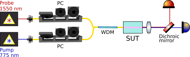
The experimental setup developed for the investigation of photorefractive effect is presented in Fig. 1: it employs a narrowband tunable laser at 1550 nm as a probe and a tunable laser at 775 nm as a pump inducing the photorefractive space-charge field. Probe and pump beams are multiplexed through the same optical fiber and coupled to the sample under test (SUT). Both optical sources are operated in continuous wave regime (CW) and have their polarization independently controlled. At the output of the SUT, light is collected by a lens, its spectral components separated using a dichroic mirror, and focused onto suitable photodetectors. The temperature of the system is stabilized by an active loop with an error of 5 mK. We note that in our working conditions, photothermal drift only induces changes of /K in the refractive index Moretti et al. (2005); this effect can be neglected compared to the one induced by photorefractivity, that is approximately three order of magnitude more important (see below).
III Cavity effect
III.1 Waveguide cavity made of chip’s end-facets
To date, the highest levels of squeezing have been obtained thanks to SPDC in resonant systems such as optical parametric oscillators Vahlbruch et al. (2016).
Integrated optics opens the possibility of fabricating monolithic squeezers that are more compact and stable than their bulk optics analogues, working either in single-pass or resonators.
This concept has been recently validated by the realisation PPLN waveguides on ZnO-doped substrate that was used to demonstrate single-mode squeezing at 1550 nm, with a noise reduction of about -6 dB in single pass configuration Kashiwazaki et al. (2020). At the same wavelengths, squeezing of -5 dB has been measured at the output of a Ti-indiffused PPLN waveguide resonator Stefszky et al. (2017) pumped with 30 mW of CW powers at 775 nm.
The observation of stronger squeezing values in such a resonant device was prevented by the occurence of photorefractive effect at higher SPDC pump powers.
Beside instabilities caused by the appearance of mode hopping of the pump beam, photorefractive effect can indeed impact cavity based devices even at weaker power conditions.
More specifically, the waveguide refractive index variation, , induced by photorefractivity can result in a phase shift and, possibly, in a detuning from perfect cavity resonance that can degrade the squeezing level Fabre et al. (1990).
This effect can also affect efficient squeezing production in LiNbO3 in single-pass configurations Yoshino et al. (2007); Kanter et al. (2002); Mondain et al. (2019); Kaiser et al. (2016) where parasitic cavity effects can arise from Fresnel’s reflections at the end-facets of the waveguide;
here, we focus on the effects of these parasite cavities. To his end, we take as SUT a 15 mm long SPE waveguide with end-facets polished perpendicular to light propagation direction and uncoated.
The propagating modes indices are (@1550 nm)=2.13 and (@775 nm)=2.18.
Corresponding Fresnel’s coefficients at the waveguide interfaces are () per facet at 1550 nm (775 nm), and the device acts as a parasitic Fabry-Perot interferometer (FPI) with a low finesse =1.30 and a FWHM of 20 pm Regener and Sohler (1985). The cavity enhancement to squeezing generation due to Fresnel’s reflections at the sample facets is incremental. At the same time, a photorefractive-induced detuning from cavity resonance can result in an overall degradation of the device transmission and give rise to instabilities.
III.2 Phenomenological description
The complexity of the dynamics of the system is well illustrated in Fig. 2 that shows the transmission trace of the probe at 1550 nm, when the SUT working temperature is 30C.
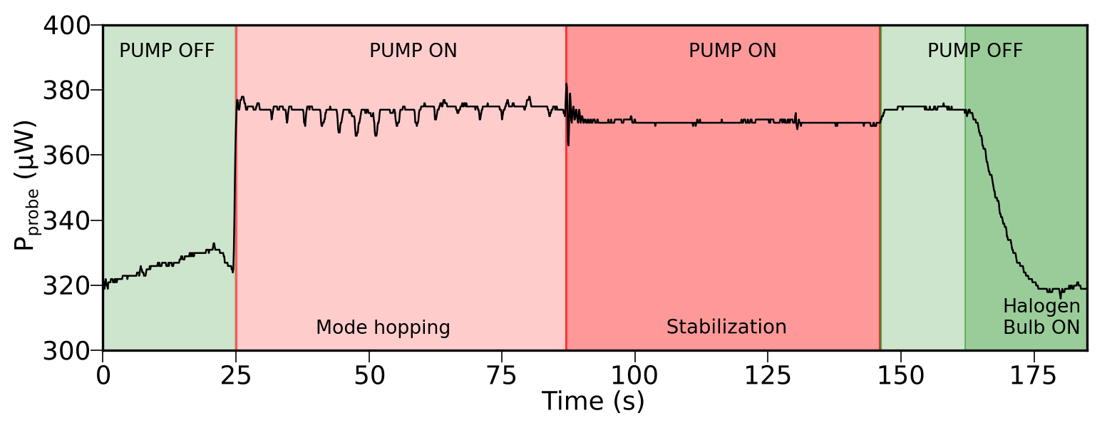
Here, green regions indicate the time-slots in which only the probe beam is sent to the SUT while red areas refer to the case in which the system is fed also with a pump beam of 5 mW power. In such weak pumping regime, we already observe photorefractive effect. The pump irradiation changes the effective refractive index seen by the probe at 1550 nm and, in turn, its transmitted power through the FPI Hellwig (2010). This is clearly visible between 25 s and 85 s when regular dips appear in the transmission trace, due to refractive index variation associated with mode hopping of the pump beam. These mode fluctuations spontaneously reduce until the system stabilizes on a given mode as witnessed by the probe transmission after 85 s. At 140 s the pump laser is turned off with little impact on the space-charge field. This is related to the long lifetime of the trapped electrons. At 165 s we illuminate the sample with a high-intensity halogen bulb (1.4 W) to accelerate the redistribution rate of the trapped electrons so as to restore the initial material conditions and beam transmission.
III.3 Model of the waveguide cavity
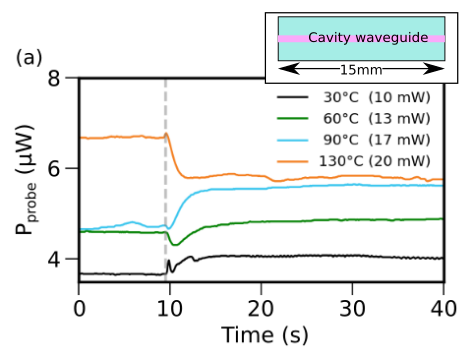
The large variety of phenomena shown in Fig. 2 suggests why photorefractivity is generally hard to predict and control. The usual countermeasure consists in increasing the SUT temperature around 100C. However, this only shifts the occuring of photorefractive effect towards higher pump powers, without completely suppressing it. We illustrate this behavior in Fig. 3a, where we show the transmission traces for the probe beam at different heating temperatures with a pump injection starting at t=10 s. At low temperatures, the pump power was adjusted so as to avoid mode hopping. For all cases, the final transmission for stabilized waveguide is different from the original one. Before reaching this point, a transient oscillatory behaviour might be observed.
To better understand the interplay between cavity and photorefractive effect, we recall the transmission of the Fabry-Perot waveguide resonator Hecht (2017):
| (1) |
with is the finesse of the cavity, the probe wavelength, =15 mm the length of the chip, the effective index of the mode without photorefraction, and the pump-induced photorefractive index modification. Since photorefractive effect barely changes Fresnel’s coefficients, we can consider constant.
From the term, we see that for weak variation of over time, the transmitted power can show an oscillatory behaviour, half a period corresponding to an index variation . This kind of variation can be observed in the C curve of Fig. 3a between 10 and 15 s, giving an overall index change ; for higher temperatures, is weaker and oscillations disappear. We note that transmission is affected by photorefractivity even at 130C. At such high temperature, a small, time-independent, refractive index shift can be observed Amodei and Staebler (1971). This constant shift slightly modifies the cavity optical resonance condition and, as a consequence, the transmitted power at the probe wavelength.
 |
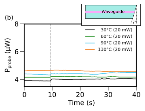 |
Beside the use of anti-reflection coatings, the most pertinent way to suppress parasitic FPI is to polish the chip end-facets with an angle in order to prevent guiding of light reflected at the interface. We confirm this concept by employing as a SUT a chip with output facets polished with a 7 angle Takaya and Shibata (2003). The corresponding transmissions are shown in Fig. 3b: all measurements are taken at a maximum pump power of 20 mW. The signature of photorefraction is removed or negligible for all working temperatures. Residual effects are due to the photorefractive inducted , that changes the fiber-to-waveguide coupling at the input of the non-resonant device, thus affecting the measured transmitted power.
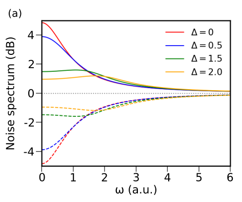
Eventually, we note that, in CV quantum optics, beside modifying the sample transmission, the detuning from perfect cavity resonance (\textDelta) induced by \textDeltan(t) can affect the dynamics of squeezing generation Fabre et al. (1990). For example, Fig. 4 a shows the quantum noise spectrum of single-mode squeezed light at the output of a resonant PPLN waveguide Stefszky et al. (2017). The detuning is normalized to the cavity linewidth.
 |
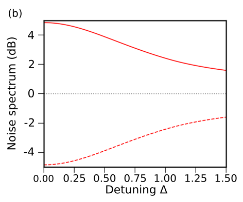 |
The squeezing spectrum (dashed lines) exhibits a minimum at a frequency that depends on the detuning and shows a noise reduction less important than the one expected in the perfectly resonant case (). This effect is more obvious when \textDelta increases. This is represented in Fig. 4b where the best squeezing (antisqueezing) is represented as functions of the detuning. As for a numerical example, for a cavity of 15 mm, with mirror reflectivity of 0.77 and 0.99 as in Stefszky et al. (2017), a variation of would correspond to a normalized detuning of 1.5 and lead to a degradation of squeezing, from an initial value of -5 dB, to only -2 dB. Similar calculations show that the same detuning would reduce an initial squeezing of -10 dB to only -5 dB.
IV Directional couplers and homodyne detection
Directional couplers are basic building blocks for any photonic integrated circuit as they permit to design light routing, (de)multiplexing and interference stages. We consider here devices exploiting evanescent-wave coupling to obtain a periodic transfer of light intensity from a waveguide to another: when two single-mode waveguides are close enough, their evanescent fields spatially overlap and give rise to a coupling between the two structures, as sketched in Fig. 5.
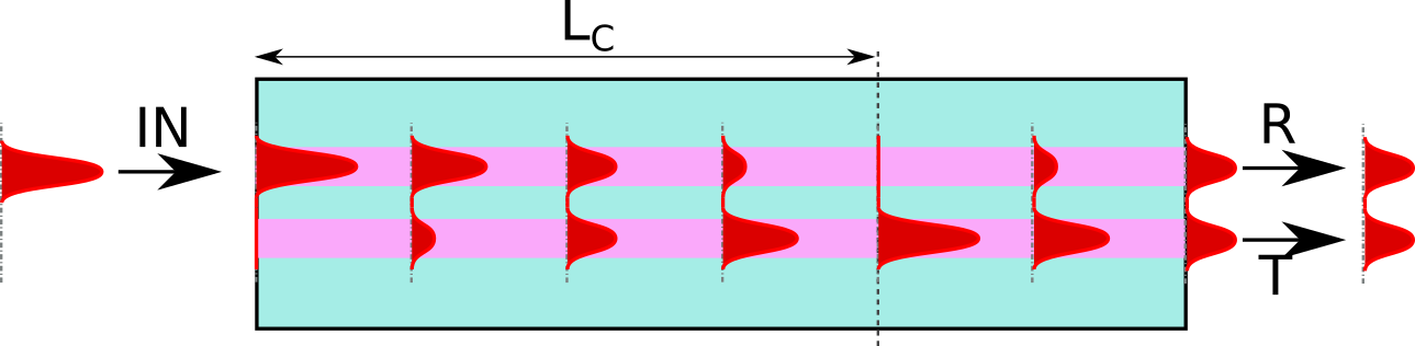
The fraction of optical power transferred to the adjacent waveguide is generally said to be transmitted, while the rest is reflected; by extension we will call the two waveguides reflecting () and transmitting (), with propagation constants and , respectively. If , light will periodically undergo a perfect transfer from a waveguide to the other during its propagation. All optical power is found in the transmitting arm after a distance referred to as the coupling length, where is the coupling constant that depends on the effective refractive indices of the modes and on the distance separating the waveguides.
In the context of CV integrated circuits, directional couplers are needed for multiple applications. On the one hand, strongly unbalanced couplers are used to pick up a fraction of a non-classical state and send it to a single photon detector for the heralded preparation of non-Gaussian states Huang (2015). On the other hand, perfectly balanced couplers are mandatory for homodyne detection, in which the properties of a state under scrutiny are retrieved by making it interfere with a local oscillator Mondain et al. (2019). Refractive index change induced by photorefractivity can affect the symmetry of directional couplers () and shift their working point. This effect is detrimental in most of practical situations.
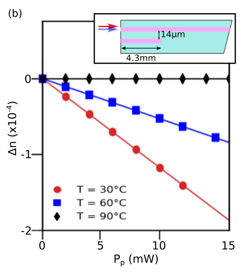
We investigate the influence of photorefractivity thanks to a passive directional coupler (sketched in the inset of Fig. 6a) consisting in a 15 mm long chip with its output facet angle-polished to prevent parasitic FPI. It comprises two waveguides of 6 µm width with 14 µm separation, corresponding to a coupling k=0.46 mm-1, i.e. mm at C for nm. The coupler length is 4.3 mm long. At the pump wavelength, the coupling between the waveguides is negligible. This geometry, although made of only one output (the reflection waveguide), is perfectly suitable to study the device sensitivity to photorefractivity.
As shown in Fig. 6a, both pump and probe beams are injected in the coupler and the probe beam exiting the chip is analyzed. When the pump beam is in the reflection waveguide, it modifies its refractive index , changing the propagation constant to . Correspondingly, the fraction of reflected probe power is:
| (2) |
with () the input (reflected) probe power.
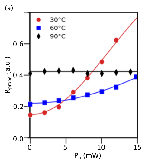
Measured coupler reflectivity at 1550 nm is plotted in Fig. 6a as a function of the pump power at 775 nm.
Experimental data have been fitted using Eq. (2) in order to infer . We assume a dependence of upon the pump power of the form where , and are constants determined by the material Ruske et al. (2003); Fujiwara et al. (1992).
Obtained values are shown in Fig. 6b. We note that, for studied pump powers, the dependence of with is linear and does not saturate. The experimental values are consistent with Fig. 3b and compatible with results published in the literature Ruske et al. (2003).
As for an example, a pump power of 10 mW induces a , close to the value of as found from the FPI analysis.
The difference between the two measured values can be explained by a combination of sample geometrical variations, due to the fabrication process, and measurement uncertainties (of the order of ).
Note that, as expected, higher temperatures reduce the photorefractivity; above 90 C, photorefractivity impact on the coupler is negligible.
 |
 |
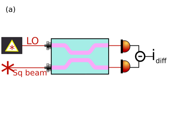
We can apply these findings to the discussion on performances of an integrated homodyne detector as the one implemented in Mondain et al. (2019). As sketched in Fig. 7a, in CV quantum optics, information on an optical beam is obtained by mixing it on a 50/50 coupler with a reference beam called local oscillator (LO) and then by detecting the intensities of the two outputs beams. Single-mode squeezing level can be obtained from the noise variance of the photocurrent difference, . For a generic coupler of reflectivity and transmissivity , the measured quantum noise is:
| (3) |
where is the squeezing parameter, is the LO field amplitude, and is the relative phase between LO and the squeezed beam. In the previous expression, we consider a perfect coherent local oscillator without classical noise. The noise of the squeezed observable (typically the electromagnetic field phase quadrature Andersen et al. (2010)) is , while the anti-squeezing on its conjugate observable (the amplitude quadrature) is . In the following we assume for simplicity and focus only on squeezing detection. For a balanced coupler, i.e. , the terms from unbalanced LO disappear and residual classical noise contributions are fully suppressed. In this optimal condition, . In experiments, to quantify the noise reduction with respect to a reference noise, squeezed light before the coupler is blocked so as to measure the vacuum noise (shot noise level) used to normalize . In integrated realizations, residual pump beam from the squeezing stage can circulate in the homodyne coupler and induce photorefractivity: this can change the splitting ratio either in the measurement or in the calibration step. From the values of Fig. 6b, we can evaluate the impact of photorefractivity on squeezing homodyne measurement. Fig. 7b shows the measured squeezing level as a function of the residual pump power circulating in the homodyne optical coupler. The estimation is made for a coupler with 14 µm-waveguide separation, working at 30C and designed to have a perfectly balanced splitting in absence of optical pumping at 775 nm. Fig. 7b shows that the splitting ratio alteration induced by photorefractivity can significantly reduce the measured squeezing level; this underestimation can easily remain unnoticed without a preliminary proper characterization of the photorefractivity.
 |
 |
Empirically, we find that a temperature of 90C is sufficient to suppress photorefractivity when the pump power is below 15 mW. However, the total effect is strongly related to the exact configuration (coupling constant, coupling length, substrate, pump power). To conclude this section we note that integrated wavelength division multiplexer (WDM) have already been integrated on LiNbO3 photonic chips Lenzini et al. (2018). Provided they are added before the homodyne detection stage, this kind of devices could be a solution to suppress residual pump power and, in turns, photorefractivity in the integrated coupler. However, such a realization would come at the cost of an increased complexity and additional losses in the circuit.
V Spontaneous parametric down conversion
We investigate the impact of photorefractivity on the nonlinear properties of a periodically poled lithium niobate waveguide (PPLN/w). In particular, due to its role in squeezing generation, we discuss the evolution of spontaneous parametric down conversion (SPDC) at different pump regimes and temperatures. The SPDC spectrum is determined by energy conservation and phase matching conditions that rule the conversion of pump photons () at 775 nm, into pairs of signal () and idler () photons at telecom wavelength (1550 nm). These can be written, in a PPLN medium, as:
| (4) |
where is the wavelength of the beam (), the corresponding refractive index, and the poling period Alibart et al. (2016). We note that the generation of single mode squeezing is achieved when signal and idler are fully degenerate Kaiser et al. (2016), in the general case two mode squeezing is obtained Heidmann et al. (1987). As the quasi-phase matching condition depends on the material refractive indices, photorefractive effect can considerably modify the SPDC working point.
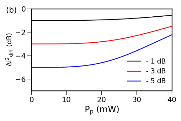
The experimental setup used to investigate the impact of photorefractivity on SPDC is depicted in Fig. 8. A tunable pump laser delivering a wavelength of 770.73 nm (774.63 nm) is injected through a fiber into a in-house 15 mm long PPLN SPE waveguide working at 30C (90C), designed to have its SPDC degeneracy around 1550 nm. The waveguide is polished so that incident beams are orthogonal to end-facets (0-cut). To comply with cavity effects, before acquiring the spectrum, we wait for the resonant system stabilization (see Fig.3).
At the output of the sample, the generated photon pairs are coupled to an optical fiber, spectrally scanned by using a tunable filter, and measured by a single-photon detector.
This characterisation method is typical for the analysis of SPDC in quantum optics Lunghi et al. (2012).
The dark count rate is on the order of 1 kcounts/s.
Note that, for all of the investigated powers, the sample works in a non-stimulated regime. As the photon pair emission rate is proportional to the pump power Tanzilli et al. (2001), an in-line fiber attenuator (not represented in Fig. 8) is used downstream the sample, in order to keep the count rate below 20 kHz to avoid detector saturation.
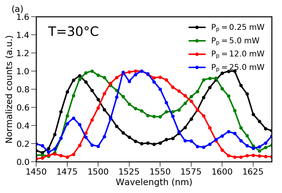
The normalized resulting SPDC spectra for different pump powers () and temperatures are shown in Fig. 9a (30C) and Fig. 9b (90C).
 |
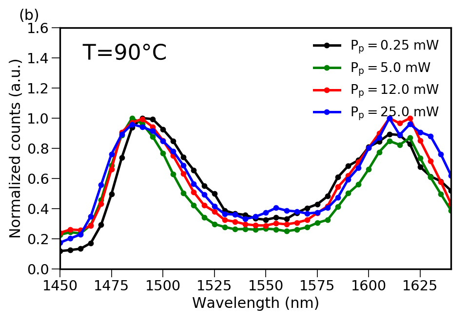 |
The pump wavelength is adjusted for each temperature in order to be out of degeneracy when =0.25 mW.
At low temperature, as expected, the photorefractive effect due to the pump power, changes the phase-matching condition.
When increases, the emission reaches the degeneracy such that idler and signal emission spectra to overlap.
Similar results have been found in Pal et al. (2015) for second-harmonic generation where a blue shift of the phase-matching wavelength has been observed.
We note that, as found for the directional coupler, phase matching is insensitive to the pump beam influence when the device is set to a temperature of 90C.
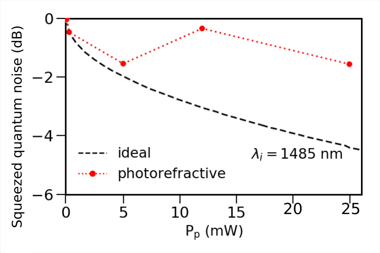
In this context, photorefractivity affects directly the squeezing generation. Indeed, the squeezing parameter, is equal to Kaiser et al. (2016), where is the nonlinear efficiency, often considered as constant in PPLN waveguides.
However, we have seen that photorefractivity modifies the phase matching conditions, and then depends on via the refractive indices in Eq. (4).
Let us compare an ideal PPNL waveguide, i.e. not affected by photorefractivity (constant nonlinearity), to a realistic one (submitted to photorefractivity).
In the first case, we take = 0.101 mW-1/2 as reported in the literature Kaiser et al. (2016).
In the second case, we take into account the degradation of the quasi-phase matching due to photorefractivity from the SPDC spectra depicted in Fig. 9a.
Both reachable squeezing levels are shown in Fig. 10.
The shifted-QPM, photorefractive PPLN (red dotted line) is strongly degraded compared to the ideal, photorefraction-free PPLN (black dashed line).
Therefore, to optimize the squeezing level, proper and careful characterisations must thus be realized on the device working conditions in order to comply with photorefractivity and to compensate for the unwanted spectral shift, by fine adjustement of the temperature and pump wavelength.
VI Conclusions
Integrated photonics enable a continuous increase of optical function complexity. This is extremely advantageous for quantum information technology and in particular in CV quantum photonics where losses and stability need to be carefully controlled. In this paper we have focused on LiNbO3-based integrated photonic circuits which represent one among the most reliable platforms for CV-quantum regime and squeezing experiments. However, LiNbO3 notoriously suffers from photorefractivity and this is particularly crucial for squeezing as it requires strong pump beams at short wavelengths. Here, we have derived a framework to analyze the impact of photorefractive effect on integrated cavities, directional couplers, and nonlinear waveguides which are building blocks for any CV integrated photonic circuits. We have demonstrated that photorefractivity might compromise the success of an experiment even in conditions far from mode hopping. A temperature increase is a viable solution to reduce photorefractivity. For the specific case-studies investigated in this work, an operating temperature of at least 90C is sufficient to suppress the impact of photorefractivity on waveguide coupling or SPDC process. Nevertheless, this strategy, even above 120C, doesn’t apply for resonators and cavities which are extremely sensitive to refractive-index variations. Therefore, particular attention should be taken to avoid parasitic cavities. If cavity is needed, the use of metal doped-LiNbO3 becomes mandatory above a certain pump power that depends on the specific waveguide technology. We believe this work might be a useful guideline to efficiently characterize LiNbO3 integrated photonic chips for squeezing experiments.
Funding
This work was conducted within the framework of the project OPTIMAL granted through the European Regional Development Fund (Fond Europeen de developpement regional, FEDER). The authors acknowledge financial support from the Agence Nationale de la Recherche (HyLight ANR-17-CE30-0006-01, SPOCQ ANR-14-CE32-0019-03, Q@UCA ANR-15-IDEX-01).
Disclosures
The authors declare no conflicts of interest.
References
- O’Brien et al. (2009) J. L. O’Brien, A. Furusawa, and J. Vučković, Nat. Phot. 3, 12 (2009).
- Tanzilli et al. (2012) S. Tanzilli, A. Martin, F. Kaiser, M. De Micheli, O. Alibart, and D. Ostrowsky, Laser & Photon. Rev. 6, 115 (2012).
- Alibart et al. (2016) O. Alibart, V. D’Auria, M. P. De Micheli, F. Doutre, F. Kaiser, L. Labonté, T. Lunghi, E. Picholle, and S. Tanzilli, J. Opt. 18, 104001 (2016).
- Andersen et al. (2010) U. Andersen, G. Leuchs, and C. Silberhorn, Laser & Photon. Rev. 4, 337 (2010).
- Kaiser et al. (2016) F. Kaiser, B. Fedrici, A. Zavatta, V. D’Auria, and S. Tanzilli, Optica 3, 362 (2016).
- Lenzini et al. (2018) F. Lenzini, J. Janousek, O. Thearle, M. Villa, B. Haylock, S. Kasture, L. Cui, H. P. Phan, D. V. Dao, H. Yonezawa, et al., Sci. Adv. 4, 1 (2018).
- Mondain et al. (2019) F. Mondain, T. Lunghi, A. Zavatta, E. Gouzien, F. Doutre, M. P. De Micheli, S. Tanzilli, and V. D’Auria, Photon. Res. 7, A36 (2019).
- Kostritskii (2009) S. M. Kostritskii, Appl. Phys. B 95, 421 (2009).
- Pal et al. (2015) S. Pal, B. K. Das, and W. Sohler, Appl. Phys. B 120, 737 (2015).
- Peter Günter (2006) J. P. H. Peter Günter, Photorefractive Materials and Their Applications 1 (Springer-Verlag New York, 2006), ISBN 978-0-387-25192-9.
- Volk et al. (1994) T. Volk, N. Rubinina, and M. Wöhlecke, J. Opt. Soc. Am. B 11, 1681 (1994).
- Kong et al. (2012) Y. Kong, S. Liu, and J. Xu, Materials 5, 1954 (2012).
- Rams et al. (2000) J. Rams, A. Alcázar-de Velasco, M. Carrascosa, J. Cabrera, and F. Agulló-López, Opt. Commun. 178, 211 (2000).
- Andersen et al. (2016) U. L. Andersen, T. Gehring, C. Marquardt, and G. Leuchs, Physica Scripta 91, 053001 (2016).
- Stefszky et al. (2017) M. Stefszky, R. Ricken, C. Eigner, V. Quiring, H. Herrmann, and C. Silberhorn, Phys. Rev. Appl. 7, 044026 (2017).
- Bazzan and Sada (2015) M. Bazzan and C. Sada, Appl. Phys. Rev. 2, 040603 (2015).
- Fujiwara et al. (1993) T. Fujiwara, R. Srivastava, X. Cao, and R. V. Ramaswamy, Opt. Lett. 18, 346 (1993).
- Caballero-Calero et al. (2006) O. Caballero-Calero, A. García-Cabañes, J. M. Cabrera, M. Carrascosa, and A. Alcázar, J. Appl. Phys. 100, 093103 (2006).
- Chanvillard et al. (2000) L. Chanvillard, P. Aschiéri, P. Baldi, D. B. Ostrowsky, M. de Micheli, L. Huang, and D. J. Bamford, Appl. Phys. Lett. 76, 1089 (2000).
- Moretti et al. (2005) L. Moretti, M. Iodice, F. G. Della Corte, and I. Rendina, J. Appl. Phys. 98, 036101 (2005).
- Vahlbruch et al. (2016) H. Vahlbruch, M. Mehmet, K. Danzmann, and R. Schnabel, Phys. Rev. Lett. 117, 110801 (2016).
- Kashiwazaki et al. (2020) T. Kashiwazaki, N. Takanashi, T. Yamashima, T. Kazama, K. Enbutsu, R. Kasahara, T. Umeki, and A. Furusawa, APL Photonics 5, 036104 (2020).
- Fabre et al. (1990) C. Fabre, E. Giacobino, A. Heidmann, L. Lugiato, S. Reynaud, M. Vadacchino, and W. Kaige, Quantum Optics 2, 159 (1990).
- Yoshino et al. (2007) K.-I. Yoshino, T. Aoki, and A. Furusawa, Appl. Phys. Lett. 90, 041111 (2007).
- Kanter et al. (2002) G. Kanter, P. Kumar, R. Roussev, J. Kurz, K. Parameswaran, and M. Fejer, Opt. Express 10, 177 (2002).
- Regener and Sohler (1985) R. Regener and W. Sohler, Appl. Phys. B 36, 143 (1985).
- Hellwig (2010) A. Hellwig, Ph.D. thesis, University of Paderborn (2010).
- Hecht (2017) E. Hecht, Optics (Pearson Education, Incorporated, 2017), ISBN 9780133977226.
- Amodei and Staebler (1971) J. J. Amodei and D. L. Staebler, Appl. Phys. Lett. 18, 540 (1971).
- Takaya and Shibata (2003) M. Takaya and K. Shibata, IEEE Journal of Lightwave Technology 21, 1549 (2003).
- Huang (2015) K. Huang, Ph.D. thesis, Ecole Normale Supérieure - ENS Paris (2015).
- Ruske et al. (2003) J.-P. Ruske, B. Zeitner, A. Tünnermann, and A. Rasch, Electron. Lett. 39, 1048 (2003).
- Fujiwara et al. (1992) T. Fujiwara, X. Cao, R. Srivastava, and R. V. Ramaswamy, Appl. Phys. Lett. 61, 743 (1992).
- Heidmann et al. (1987) A. Heidmann, R. J. Horowicz, S. Reynaud, E. Giacobino, C. Fabre, and G. Camy, Phys. Rev. Lett. 59, 2555 (1987).
- Lunghi et al. (2012) T. Lunghi, C. Barreiro, O. Guinnard, R. Houlmann, X. Jiang, M. A. Itzler, and H. Zbinden, J. Mod. Opt. 59, 1481 (2012).
- Tanzilli et al. (2001) S. Tanzilli, H. D. Riedmatten, W. Tittel, H. Zbinden, P. Baldi, M. D. Micheli, D. Ostrowsky, and N. Gisin, Electron. Lett. 37, 26 (2001).