Coherent transport of spin by adiabatic passage in quantum dot arrays
Abstract
We introduce an adiabatic transfer protocol for spin states in large quantum dot arrays that is based on time-dependent modulation of the Heisenberg exchange interaction in the presence of a magnetic field gradient. We refer to this protocol as spin-CTAP (coherent transport by adiabatic passage) in analogy to a related protocol developed for charge state transfer in quantum dot arrays. The insensitivity of this adiabatic protocol to pulse imperfections has potential advantages for reading out extended spin qubit arrays. When the static exchange interaction varies across the array, a quantum-controlled version of spin-CTAP is possible, where the transfer process is conditional on the spin states in the middle of the array. This conditional operation can be used to generate -qubit entangled GHZ states. Using a realistic noise model, we analyze the robustness of the spin-CTAP operations and find that high-fidelity (95) spin eigenstate transfer and GHZ state preparation is feasible in current devices.
I Introduction
The study of the coherent dynamics of spin ensembles in solids has a long history.Ernst et al. (1987) More recent advances allow the study of single-spins in mesocopic and nanoscale devices.Awschalom and Kikkawa (1999); Žutić et al. (2004) Physical confinement to low-dimensions enhances interaction effects and leads to novel quantum coherent phenomena involving spins such as spin-charge separation in Luttinger liquidsGiamarchi (2004) and skyrmions in quantum Hall ferromagnets.Sondhi et al. (1993); Barrett et al. (1995) In zero-dimensional semiconductor quantum dots, spin-dependent effects predominantly arise from the combination of repulsive Coulomb interactions and the Pauli exclusion principle.Hanson et al. (2007) Motivated by quantum information applications,Loss and DiVincenzo (1998) there is now increasing interest in the coherent transport of spin in large arrays of tunnel-coupled quantum dots as a means to distribute quantum information, or to realize more efficient spin-readout, across the array.Taylor et al. (2005); Friesen et al. (2007); Baart et al. (2016); Fujita et al. (2017); Mills et al. (2019); Kandel et al. (2019); Sigillito et al. (2019a)
A proposed method to achieve charge transport in quantum dot arrays is known as coherent transport by adiabatic passage (CTAP).Greentree et al. (2004); Rahman et al. (2010); Huneke et al. (2013); Ban et al. (2018); Picó-Cortés et al. (2019); Ban et al. (2019) This protocol uses an electrical analog of the well-known stimulated Raman adiabatic passage (STIRAP) pulse sequence from atomic, molecular, and optical (AMO) physics to move the electron coherently across the array by keeping it in an adiabatic dark state.Vit ; Vitanov et al. (2017) Charge coherence times in quantum dots are often relatively short ( ns),Hayashi et al. (2003); Petta et al. (2004); Petersson et al. (2010) so far preventing the realization of CTAP in practice. However, the elegance of this method motivates the search for spin based analogs of CTAP (spin-CTAP) that may allow robust spin transport. Single spins confined in semiconductor quantum dots can have long spin-dephasing times (s) compared to the timescale of exchange-based spin dynamics ( ns),Petta et al. (2005); Veldhorst et al. (2015); Reed et al. (2016); He et al. (2019) setting up much more favorable conditions for adiabatic transfer protocols.
In this Article, we develop the theoretical framework of spin-CTAP using the Heisenberg exchange interaction in a linear array of quantum dots in a magnetic field gradient. The combination of exchange interactions and a magnetic field gradient leads to an effective Ising interaction.Meunier et al. (2011); Russ et al. (2018); Zajac et al. (2018); Watson et al. (2018) By modulating the exchange interaction in time, we can resonantly drive flip-flop transitions of electron spins on neighboring dots of a linear array.Nichol et al. (2017); Sigillito et al. (2019a); Takeda et al. (2020) As we show here, applying this exchange modulation according to CTAP pulse sequences allows adiabatic spin-transfer across large quantum dot arrays.
The investigation of spin transport in Heisenberg coupled spin chains dates back to foundational work on quantum magnetism,Bloch (1930) with many studies focused on optimized state transfer for quantum information applications.Bose (2003); Christandl et al. (2004); Osborne and Linden (2004); Murphy et al. (2010); Yao et al. (2011); Makin et al. (2012) Our approach differs in detail from these previous works because of the large magnetic field gradient imposed by a micromagnet and the use of local, time-dependent control of the exchange interaction throughout the array. For many spin systems, local control of exchange coupling is difficult to realize; however, it is readily achievable in quantum dot arrays through electrical driving of the gates used to form the dots.Petta et al. (2005); Veldhorst et al. (2015); Reed et al. (2016); He et al. (2019) Our spin transfer and entanglement generation protocols are immediately applicable to current experiments.Mills et al. (2019); Kandel et al. (2019); Volk et al. (2019) The overall simplicity and robustness to pulse imperfections make adiabatic spin transfer a promising method for the readout of large quantum dot arrays. Motivated by similar considerations, a related adiabatic transfer scheme was recently implemented experimentally in an array of GaAs quantum dot spin-qubits.Kandel et al. (2020)
The paper is organized as follows: In Sec. II, we introduce our theoretical model for extended arrays of quantum dots based on a Hubbard model. We then briefly review charge-CTAP in a quantum dot array containing a single electron. In Sec. III, we transition to a regime where each site in the quantum dot array is occupied by a single electron. We include the effects of a magnetic field gradient and develop the theory of spin-CTAP for three dot arrays, specifically considering the fully-polarized subspace with a single spin-flip. Varying the tunnel coupling, and therefore exchange between adjacent sites, along the array shifts subspaces with different numbers of spin flips out of resonance with the transfer protocol. We use this effect to realize a quantum-controlled version of spin-CTAP conditional on the spin state of the middle electron. We benchmark the performance of our spin-CTAP pulses in the presence of a realistic noise model and study the effects of imperfections in the adiabatic pulse sequences. In Sec. IV, spin-CTAP is generalized to arbitrarily large quantum dot arrays. In Sec. V, we show how to use quantum-controlled spin-CTAP to generate many-qubit Greenberger-Horne-Zeilinger (GHZ) states.Nielsen and Chuang (2011) Including the effects of noise, high-fidelity GHZ state preparation is possible for three dots, with persistent entanglement achievable in arrays of up to 11 dots. We present our conclusions in Sec. VI.
II CTAP in Quantum dot arrays
Arrays of quantum dots with more than three independent, electrically controllable sites are now routinely studied in experiment.Zajac et al. (2016); Nichol et al. (2017); Mortemousque et al. (2018); Mills et al. (2019); Sigillito et al. (2019b); Kandel et al. (2019); Volk et al. (2019); Dehollain et al. (2020) A common approach to analyze these experiments is to approximate the low-energy Hamiltonian by a single-band Hubbard model
| (1) |
where is a tunnel coupling matrix element between the lowest orbital state on each dot, is the local Coulomb repulsion on each dot, and is the local chemical potential. Here, is a Fermion annihilation operator on dot with spin = or , and .
When there is only a single electron in a fixed spin state in the entire array, then the Hamiltonian has a single-particle description
| (2) |
where is the electronic state with a single excess electron in dot in a spin-down state. For a linear three dot array with uniform chemical potentials, this Hamiltonian has the representation in the basis as
| (3) |
The idea of CTAP is that the electron charge can be adiabatically transferred from dot 1 to dot 3 by taking advantage of special properties of three-level systems with this Hamiltonian.Greentree et al. (2004) In particular, for any value of there is a zero-energy eigenstate of (i.e., ) that takes the simple form
| (4) |
In AMO physics, this zero energy state is called a “dark state” because it is a nontrivial superposition state with zero population in the intermediate state of the three-level system. Oftentimes, this intermediate state is an optically excited state that emits photons, which is the origin of the terminology.Scully and Zubairy (1997)
The dark state has a minimal energy gap to the other two eigenstates of (often called “bright states”) by an amount
| (5) |
For a general time-dependent Hamiltonian, the adiabaticity condition to remain in the adiabatic eigenstate takes the form . Since the adiabatic dark state always has a finite gap from the other two adiabatic bright states, any sufficiently slowly evolving pulse sequence will satisfy the adiabaticity condition and maintain population in the dark state. State transfer is achieved for pulse sequences that start with and ends with such that transforms from at the beginning of the sequence to at the end. In AMO physics, this adiabatic passage sequence, with its characteristic “counterintuitive” ordering, is commonly referred to as stimulated Raman by adiabatic passage (STIRAP).Vit Applying such a pulse sequence for a single electron in a quantum dot array leads to coherent transport of charge by adiabatic passage (CTAP).Greentree et al. (2004) By adiabatically turning on a large tunnel coupling on the middle dots to energetically isolate an extended zero energy state, this three-site CTAP protocol can be directly generalized to arbitrarily large arrays of dots.Greentree et al. (2004)
III Spin-CTAP in Quantum Dot Arrays
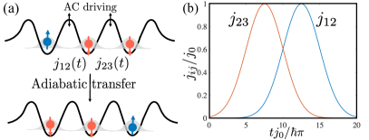
We now consider the generalization of CTAP to the spin degree of freedom. Instead of working in the limit of a single electron in the quantum dot array, we consider the half-filled case with one electron per dot. Strong Coulomb repulsion ( meV) leads to the formation of a Mott insulating state where the only mobile degrees of freedom at low energies are the electron spins [see Fig. 1(a)]. Integrating out the double occupancies from a single-band, spin-full Hubbard model at half-filling generically leads to an effective Heisenberg Hamiltonian for the spins at lowest order in
| (6) |
where is the exchange interaction between the spins on dots and , is the local magnetic field experienced by spin averaged over the orbital wavefunction and is the local spin-1/2 operator on dot for the Pauli matrix (. The electronic -factor 2 in silicon. The total field includes contributions from the global external field and a local field induced by an on-chip micromagnet.Russ et al. (2018) The exchange interaction can be modulated in time by changing the tunnel barriers that separate the quantum dots.Petta et al. (2005); Veldhorst et al. (2015); Reed et al. (2016); He et al. (2019) In the regime we consider here, where the overall Zeeman energy is much greater than the temperature , we can initialize the ground state of a single dot using energy selective tunneling.Elzerman et al. (2004) Other sites in the array can then be loaded by shuttling electronsBaart et al. (2016); Fujita et al. (2017); Mills et al. (2019) or applying pairwise SWAP operations.Nichol et al. (2017); Kandel et al. (2019); Takeda et al. (2020); Sigillito et al. (2019a) Readout can also be accomplished through spin transport to dots used for spin-to-charge conversion and charge sensing in the array.Hanson et al. (2007)
Single-spin addressability can be achieved in these systems by applying a varying magnetic field across the array that is larger across each pair of sites than the pairwise exchange interaction.Loss and DiVincenzo (1998) In this regime, we can write an effective Hamiltonian in the adiabatic approximation as
| (7) |
where is the time-averaged exchange, are spin raising/lowering operators, is the amplitude of the exchange oscillating at a frequency near the difference in Zeeman frequency , and is the local spin-frequency including a perturbative correction from the time-averaged dc exchange interaction.Sigillito et al. (2019a) The condition for the rotating wave approximation to be valid is that the difference in Zeeman energy between each pair of sites is much larger than the exchange and the detuning from resonance. Otherwise, we do not make any assumptions about the spatial profile of the magnetic field. Several recent experiments have operated in the same regime studied here with a large magnetic field gradient and ac exchange driving to realize spin transport or entangling gates.Nichol et al. (2017); Takeda et al. (2020); Sigillito et al. (2019a)
The effective Hamiltonian conserves , which implies that, when restricted to the fully-polarized subspace with a single spin-flip, the many-body dynamics has a single particle description. In analogy to a particle in a discrete lattice, the transverse exchange interactions act as tunneling terms, while the longitudinal exchange interactions and magnetic fields act as local potentials. We exploit this simplified description to design spin-CTAP pulse sequences. Building on this, we then take advantage of the many-body interacting nature of the problem to realize a form of quantum-controlled spin-CTAP that can be used to generate GHZ states in quantum dot arrays.
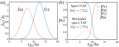
In the subsections below, we consider a linear array of three silicon quantum dots and show how to achieve state transfer . In Sec. IV, we show how to generalize our results to arbitrarily large one-dimensional arrays. The basic control sequence is illustrated in Fig. 1(b). This pulse sequence has the “counter-intuitive” ordering that is turned on before , which, we show below, ensures that the system remains adiabatically in the dark state of the three-level system without ever directly exciting the intermediate state .Vit ; Greentree et al. (2004); Vitanov et al. (2017) We first study state transfer for idealized Gaussian pulses
| (8) | ||||
| (9) |
where is the peak amplitude, is the mean center of the two pulses and is the pulse width, which is set to be the same as the timing offset between the two pulses. For we set and define a maximal cutoff time such that for . In practice, it may be difficult to realize ideal Gaussian pulses; however, the adiabatic transfer protocol only relies on the existence of a well-defined dark state that satisfies the adiabaticity condition. As a result, it is robust to small pulse imperfections as we describe in more detail in Sec. III.4.
III.1 Resonantly Driven Spin Subspace
We now consider the transfer of the spin state across a three-dot array. Restricting to the subspace and moving into a rotating frame with and , the Hamiltonian in the basis takes the form [see Fig. 2(a) for the level diagram]
| (10) |
where the “two-photon” energy detuning (terminology is taken from quantum optics, e.g., Ref. Scully and Zubairy, 1997) is , the “single-photon” energy detuning is , the bare energies are , and is an energy offset. The phase of is set by the phase of the ac exchange drive.Sigillito et al. (2019a) For illustrative purposes, we have chosen a magnetic field gradient profile with , so that the level diagram in the subspace maps to a canonical system. This assumption is not required and our numerical simulations below are performed for the more natural profile .Zajac et al. (2018)
Similar to Eq. (3), we can write down the adiabatic dark state of for = 0 and any value of
| (11) |
which satisfies for all times . This state has a minimal energy gap to the other two adiabatic eigenstates (the bright states) by an amount
| (12) |
Thus, by choosing a sufficiently slowly varying exchange , we can ensure that the adiabaticity condition is satisfied. In this limit, the system will remain in the adiabatic eigenstates during the evolution. Note that the precise values of are not relevant to the design of the pulse sequence because these values only enter into the resonance conditions for the ac driving fields. In the next section, however, we will show that when the subspace is tuned into resonance, then the behavior of the subspace sensitively depends on the relative values of and .
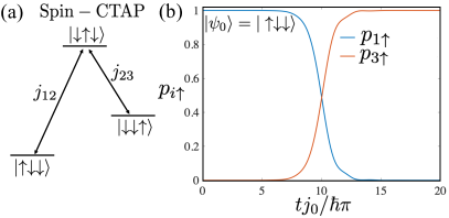
As an example of the spin-CTAP performance, we show the population dynamics of the two spin states under this driving protocol in Fig. 2(b). When the initial state is , it evolves adiabatically into the state with high fidelity . Finally, we remark that when the system is initialized in the state , then the left-to-right spin-CTAP pulse sequence has the “intuitive” ordering and can still transfer the spin-up state across the array from right-to-left. There is an important difference, though, that this right-to-left process is mediated by the two adiabatic bright states instead of the dark state. As a result, this “backwards” right-to-left transfer process generally has a lower fidelity than the left-to-right transfer process.
III.2 Blockaded Spin Subspace
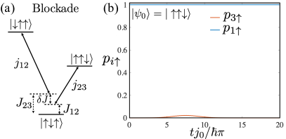
We next describe how to realize a quantum-controlled version of spin-CTAP that is conditioned by the spin state of the middle electron. In the subspace, the Hamiltonian in the basis takes the same form as Eq. (10) with , , and the shifted energies [see Fig. 3(a)]. The complex conjugation can be understood as arising from a time-reversal operation associated with switching to this subspace. These modifications imply that if we set , then the sector will have a finite one- and two-photon detuning and , respectively. As a result, for a finite exchange gradient , the single-photon detuning becomes nonzero.
Despite the different effective Hamiltonians, when the subspace still undergoes a transfer process from the state to . This transfer proceeds through a different mechanism, however, because it is effectively driving the transfer from right to left (3 to 1) instead of left to right (1 to 3). As we mentioned in the previous subsection, in the adiabatic limit, this reversed state transfer process is mediated by the two bright states, but the transfer fidelity still converges to one in the ideal limit. Thus, for , the ideal transfer process will effectively map the spin population across the array in both subspaces.
On the other hand, when and the system is tuned for spin-CTAP in the subspace, we now show that the subspace is blocked from adiabatic transport. Starting from the state with , we can calculate the associated adiabatic eigenstate for finite in the limit and
| (13) |
As a result, the adiabatic spin-state configuration in this subspace remains localized during the spin-CTAP pulse sequence. This implies that we can realize a quantum-controlled version of spin-CTAP where the spin state of the middle electron acts as the control qubit. As we show in Fig. 3(b), when the middle spin is pointing up , the spin population returns to dot 1 at the end of the pulse sequence.
For the transfer process to be adiabatic, we require the pulse width and overall length to be large compared to and . In Fig. 2(b) and Fig. 3(b), we took , and . These values satisfy both these constraints for the experimentally relevant parameters of MHz and s.Zajac et al. (2018); Watson et al. (2018) An interesting subject for future work will be to consider “shortcuts to adiabaticity” to speed up this transfer process without reducing the fidelity.Oh et al. (2013); Torrontegui et al. (2013); Li et al. (2018); Ban et al. (2019)
III.3 Effect of Noise
To characterize the performance of spin-CTAP under more realistic conditions, we numerically characterize the performance of the protocol in the presence of noise in both the local magnetic field on each dot and the exchange interaction. For illustrative purposes, we focus on the simplest realization of spin-CTAP with three quantum dots in the resonantly driven subspace. We use a noise model, described in more detail in our recent work,Gullans and Petta (2019) which is parameterized by the coherence time on each dot and a quality factor that determines the envelope decay rate for exchange oscillations between dots and . The decoherence processes are modeled by adding noise in the parameter, while the decoherence is modeled by coupling the same noise field to the parameters and .
| (14) | ||||
| (15) | ||||
| (16) |
where the amplitude of the noise on each dot is given by , is the amplitude of the noise in eV2/Hz and are high/low frequency cutoffs, , and . We make the simplifying assumptions the noise is quasistatic over the relevant timescales and that and do not vary throughout the array.
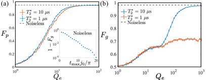
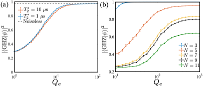
In Fig. 4(a), we show that spin-CTAP becomes robust against noise when transferring spin eigenstates already at relatively modest values of and s, which is quantified by the projection fidelity . Under these conditions, we find that the main source of decoherence arises from charge noise that leads to a finite . We see very little change when increasing from 1-10 s.
It is also of interest to consider the performance of the transfer protocol for more general quantum states. We characterize this fidelity by treating the spin-CTAP transfer process
| (17) |
as a quantum channel that maps an arbitrary quantum state on the first site to the last site and traces over the remaining sites in the system. In the ideal case, this channel acts as an identity operation (up to a deterministic -rotation that we correct) on the single-qubit Hilbert space of the transferred site. As a result, we can use the average gate fidelity to characterize the performance of the transfer protocolNielsen and Chuang (2011)
| (18) |
where is the Haar measure over the quantum states of a single-qubit. In the inset to Fig. 4(a) we show vs. in the limit of zero noise, which illustrates that the ideal fidelity rapidly converges to one. The results for including noise as a function of are shown in Fig. 4(b). Interestingly, the fidelity first plateaus near before increasing towards the noiseless limit at large values of . The initial plateau coincides with the convergence of the projection fidelity, while the slower increase with arises because the transfer of superposition states are sensitive to phase fluctuations in the wavefunction that vary from shot-to-shot due to the noise. A related feature observed in the fidelity is the much stronger dependence on . When the total transfer time [s in Fig. 4(b)] becomes comparable to , the fidelity substantially decreases from the noiseless limit due to shot-to-shot variations in the phase accumulation during the transfer process. This behavior is in sharp contrast to what was observed for , which is insensitive to phase fluctuations even when .
Finally, we remark that the average gate fidelities calculated here are comparable to measured fidelities for SWAP gates under similar conditions.Nichol et al. (2017); Takeda et al. (2020); Sigillito et al. (2019a) Thus, we conclude that, under some conditions, spin-CTAP is a viable alternative to sequential SWAP gates for transferring spin states in the array.
III.4 Imperfections in AC Exchange Driving
A central requirement of our proposal is the ability to simultaneously turn on exchange between every pair of sites across the array. Achieving this regime can be challenging and often leads to a nonlinear dependence of the exchange on the external gate voltages.Qiao et al. (2020); Pan et al. (2020) As a result, it may be difficult in practice to realize the ideally shaped Gaussian pulses considered in the previous section. Fortunately, the adiabatic nature of the control scheme renders spin-CTAP largely insensitive to these effects.
Another source of non-idealities is the potential for crosstalk between gates.van der Wiel et al. (2003); Hensgens et al. (2017); Mills et al. (2019); Volk et al. (2019) In the context of our work, one needs to avoid an effect whereby modulating the exchange on one pair of dots induces non-negligible ac exchange driving on neighboring pairs. Provided the magnetic field gradient between sites is non-uniform across the array, which is typical in devices where the gradient is produced by a proximal micromagnet,Sigillito et al. (2019b) this ac exchange driving will be off-resonant. As a result, these cross-driving effects can be neglected for the weakly driven limit considered here. For example, for an ac exchange driving of 10 MHz and a gate crosstalk of 10% or less, the variation or disorder in the magnetic field gradient should be much greater than 40 T to avoid cross-driving effects.
To study the impact of pulse distortions more quantitatively, we use a simple model for the exchange interaction described in Ref. Zajac et al., 2018. In a single-band Fermi-Hubbard model for a quantum dot array, the exchange has the scaling , where eV is the tunneling between the two dots and meV is the on-site interaction (estimates are for Si/SiGe quantum dots Zajac et al. (2018)). By modeling the barrier between the two quantum dots as a square well and using the WKB approximation, one can derive a functional form for the exchange
| (19) |
where and are the potential barrier height and width, is the energy of the unperturbed states, and is the electron mass. Using the approximation , where is the voltage on the barrier separating the two dots we obtain a precise prediction for the dependence of on the barrier gate voltage, which provides a good match to experimental data.Zajac et al. (2018)
Our spin-CTAP proposal can be realized by modulating the barrier gate voltages between dots and as , where is a slowly-varying envelope for the ac modulation term. Assuming is a weak perturbation, we can expand the exchange as
| (20) |
where are the derivatives of the exchange profile. In the rotating wave approximation we only need to account for the dc exchange term and the term that oscillates near the difference in Zeeman energies between the two dots. As a result, we can regroup the terms to arrive at the expression
| (21) |
where we defined and the first term corresponds to a slowly varying shift in the dc exchange due to the ac driving. For the dependence on given by Eq. (19), we can calculate the leading order correction to the dc and ac exchange profile by approximating the dependence of the exchange on barrier gate voltage by a pure exponential . This approximation leads to particularly simple expressions for the slowly-varying parameters
| (22) | ||||
| (23) |
Since is directly proportional to the ac amplitude on the middle barrier voltage, this shows that the the dc/ac exchange amplitude has a quadratic/cubic nonlinear correction in .
It is most natural in experiments to design a Gaussian envelope directly for the middle barrier voltage , which does not account for these nonlinear corrections. In Fig. 5(a), we show the exchange pulse profile for this control strategy, including the nonlinear correction from Eq. (23). We took similar parameters as in Fig. 2, but with a five times larger value of peak ac exchange value MHz to amplify the effect of the shift in the dc exchange and the ac exchange pulse distortions. In Fig. 5(b), we show the performance of spin-CTAP and blockaded spin-CTAP in the presence of these pulse imperfections. Although the intermediate dynamics has slight distortions compared to the ideal case, the fidelity for state transfer is nearly identical. This result is expected based on the intrinsic robustness of these transfer schemes to pulse imperfections and slowly varying perturbations provided one chooses an adiabatic pulse that starts with and ends with .
IV Multidot spin-CTAP
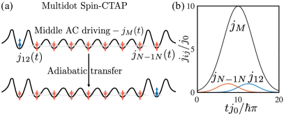
The long-range transfer of spin states in extended arrays is a long-standing goal for quantum-dot based spin qubits.Taylor et al. (2005); Friesen et al. (2007); Baart et al. (2016); Fujita et al. (2017); Mills et al. (2019); Kandel et al. (2019); Sigillito et al. (2019a) In the context of charge based transport, Greentree et al. showed that a natural generalization of CTAP from three dots to arbitrarily large one-dimensional arrays of odd numbers of dots can be obtained by modulating a large tunnel coupling in the middle of the array.Greentree et al. (2004) Partially motivated by recent experimental work in large quantum dot arrays,Zajac et al. (2016); Mortemousque et al. (2018); Mills et al. (2019); Sigillito et al. (2019b); Kandel et al. (2019); Volk et al. (2019); Dehollain et al. (2020) we now consider the multidot generalization of spin-CTAP. By applying a large ac exchange field on the middle dots for odd , we can effectively isolate a single many-body spin state in the middle of the array that is coupled to the outer two spins by weaker driving of the ac exchange [see Fig. 6(a)]. For even , adiabatic transfer is still possible, but it does not proceed through a zero energy dark state, which generally reduces the efficiency and transfer fidelities of the protocol.Greentree et al. (2004) At a qualitative level, our approach is reminiscent of other methods for long-range coupling of spin qubits using intermediate states.Mehl et al. (2014); Srinivasa et al. (2015); Baart et al. (2017); Croot et al. (2018); Malinowski et al. (2018)
To better understand the dynamics in this limit, we study the resonantly driven Hamiltonian in the rotating frame in the basis of states
| (24) |
where is the ac exchange interaction in the middle of the array (assumed to be uniform). Setting , for odd there is a zero energy state
| (25) |
Denoting the energy eigenstates for the delocalized spin states as , the energy gaps between neighboring levels all scale as . As a result, for sufficiently large , we can reduce the problem to a three-level system in the basis
| (26) |
where and . Applying the spin-CTAP pulse sequence for given by Eqs. (8)-(9) now achieves spin transport across the entire array of dots.
To achieve the multidot transfer process in an adiabatic manner, we also pulse on the exchange in the middle of the array. This approach is inspired by the original CTAP proposal.Greentree et al. (2004) In particular, as illustrated in Fig. 6(b), we use an additional Gaussian ac exchange pulse on the middle spins
| (27) |
A schematic level diagram for the multidot spin-CTAP protocol is shown Figs. 7(a–b). For our perturbative description above to be valid we require that . Since the transfer time scales as this implies that . As a result, has to scale linearly with and the maximum value of has to scale as to keep a constant transfer time in the large limit. We remark that the scaling for is expected from general bounds on the speed of information spreading in local Hamiltonian systems.Lieb and Robinson (1972)
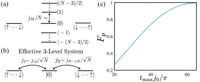
An example of the multidot spin-CTAP performance is shown in Fig. 7(c) for nine dots in a linear array.Zajac et al. (2016) We observe projection fidelities for transferring spin eigenstates that exceed for sufficiently long pulse times. As we noted above, the adiabaticity condition becomes more difficult to satisfy for large because of decreasing gaps between the dark state and other nearby eigenstates. In principle, this can be overcome by increasing the drive parameter on the middle dots; however, this becomes difficult to realize in practice. As a result, the requisite pulse time will generally increase with .
V GHZ State Generation
We now show how to extend the pulse sequences described above to generate multipartite entanglement of the spins. The blockaded version of spin-CTAP for a linear array of three quantum dots can be realized whenever there is a difference in the dc exchange for each adjacent pair of dots in the array. Under these conditions, there is a natural method to generate entangled GHZ states by applying the spin-CTAP protocol to the state
| (28) |
where is a phase that will vary with the pulse profile and external noise.
Applying a pulse on spin three, we arrive at the state
| (29) |
which is equal to a GHZ state up to a single-qubit rotation. In Fig. 8(a), we show the state fidelity in the presence of noise after correcting the random phase . We see that the GHZ state fidelity is comparable to the fidelity for transferring spin eigenstates. The noiseless limit is higher in this case than shown in Fig. 4(a) because the state comprises half the amplitude of the GHZ state and incurs no errors in our model for the spin-CTAP process. To spectroscopically determine the phase and directly measure the state fidelity in experiment, one can perform a measurement of the parity operator .Nielsen and Chuang (2011)
Similar to the three-dot case, we can realize a type of quantum-controlled multidot spin-CTAP by taking the value of the time-averaged exchange in the middle of the array, for , to be different from the two ends and . Under these conditions, we can extend the GHZ state generation scheme to arbitrarily large arrays by sequentially growing the size of the GHZ state by two qubits in each time step as follows: assume we are given an GHZ state on the middle qubits
| (30) |
We next flip spin one into an up state and then apply the pulse sequences from Eq. (8) and Eq. (27). Under ideal conditions, this operation will transform the state
| (31) |
which is equal to a GHZ state up to a single-qubit -rotation and pulse on the rightmost dot
| (32) |
The main challenge in applying this GHZ state preparation scheme is the long-transfer time associated with each step in the operation, which makes the protocol sensitive to noise. In Fig. 8(b), we show the performance of this GHZ state generation scheme for characteristic parameters up to 11 dots obtained from full numerical simulations of the multi-dot spin dynamics. Although we can successfully generate 11 qubit entanglement with this approach, achieving the highest fidelities requires much larger values of compared to the three-dot case. Furthermore, the transfer times become comparable to for , which begins to limit the achievable fidelities. A more practical GHZ state preparation scheme for likely involves local CNOT gates applied to the two ends to sequentially grow the GHZ state.Nielsen and Chuang (2011) This method has the advantage over our proposal of not requiring full state transfer in each step.
VI Conclusions
We have introduced an adiabatic protocol for spin transfer across arbitrarily large arrays of quantum dots that we refer to as spin-CTAP. The spin transfer protocol is realized in the one excitation subspace above the ground state of a spin-1/2 chain of Heisenberg exchange coupled spins in the presence of a large magnetic field gradient. Our approach is based on time-dependent modulation of the exchange interaction near the resonance frequency for nearest-neighbor flip-flops in the array. By controlling the static exchange profile across the array, we can also realize a quantum-controlled version of spin-CTAP, whereby the presence of spin flips in the middle of the array blocks the spin transfer protocol. Quantum controlled spin-CTAP can be used to generate large GHZ states.
Spin-CTAP has several applications to quantum information processing with quantum dot spin qubits. In particular, high-fidelity transfer of spin-eigenstates is feasible even in the presence of modest amounts of noise in the spin sector. Thus, this approach may find immediate use in scaling up spin readout in two-dimensional arrays where the central spins cannot be directly coupled to a nearby charge sensor. The simplicity of the control sequence may have advantages for achieving high-fidelity state transfer for some applications. The adiabatic nature of the protocol makes it highly robust to pulse imperfections, but leads to relatively slow transfer times, making it more difficult to transfer superposition states than spin eigenstates. Reducing the strength of the noise by an additional order of magnitude would allow high-fidelity transfer of superposition states. Such a coherent transfer process could be used to distribute long-range entanglement across the array to implement nonlocal quantum gates.
Acknowledgements.
We thank T. Ladd, G. Platero, A. Sigillito, and C. Tahan for helpful discussions. Funded by DARPA grant No. D18AC0025, Army Research Office grant No. W911NF-15-1-0149, and the Gordon and Betty Moore Foundation’s EPiQS Initiative through Grant GBMF4535.References
- Ernst et al. (1987) R. R. Ernst, G. Bodenhausen, and A. Wokaun, Principles of Nuclear Magnetic Resonance in One and Two Dimensions (Oxford Univ. Press, Oxford, 1987).
- Awschalom and Kikkawa (1999) D. D. Awschalom and J. M. Kikkawa, Electron Spin and Optical Coherence in Semiconductors, Phys. Today 52, 33 (1999).
- Žutić et al. (2004) I. Žutić, J. Fabian, and S. Das Sarma, Spintronics: Fundamentals and applications, Rev. Mod. Phys. 76, 323 (2004).
- Giamarchi (2004) T. Giamarchi, Quantum Physics in One Dimension (Oxford University Press, 2004).
- Sondhi et al. (1993) S. L. Sondhi, A. Karlhede, S. A. Kivelson, and E. H. Rezayi, Skyrmions and the crossover from the integer to fractional quantum Hall effect at small Zeeman energies, Phys. Rev. B 47, 16419 (1993).
- Barrett et al. (1995) S. E. Barrett, G. Dabbagh, L. N. Pfeiffer, K. W. West, and R. Tycko, Optically Pumped NMR Evidence for Finite-Size Skyrmions in GaAs Quantum Wells near Landau Level Filling , Phys. Rev. Lett. 74, 5112 (1995).
- Hanson et al. (2007) R. Hanson, L. P. Kouwenhoven, J. R. Petta, S. Tarucha, and L. M. K. Vandersypen, Spins in few-electron quantum dots, Rev. Mod. Phys. 79, 1217 (2007).
- Loss and DiVincenzo (1998) D. Loss and D. P. DiVincenzo, Quantum computation with quantum dots, Phys. Rev. A 57, 120 (1998).
- Taylor et al. (2005) J. M. Taylor, H. A. Engel, W. Dür, A. Yacoby, C. M. Marcus, P. Zoller, and M. D. Lukin, Fault-tolerant architecture for quantum computation using electrically controlled semiconductor spins, Nature Phys. 1, 177 (2005).
- Friesen et al. (2007) M. Friesen, A. Biswas, X. Hu, and D. Lidar, Efficient Multiqubit Entanglement via a Spin Bus, Phys. Rev. Lett. 98, 230503 (2007).
- Baart et al. (2016) T. A. Baart, M. Shafiei, T. Fujita, C. Reichl, W. Wegscheider, and L. M. K. Vandersypen, Single-spin CCD, Nature Nanotechnol. 11, 330 (2016).
- Fujita et al. (2017) T. Fujita, T. A. Baart, C. Reichl, W. Wegscheider, and L. M. K. Vandersypen, Coherent shuttle of electron-spin states, npj Quantum Inf. 3, 1 (2017).
- Mills et al. (2019) A. R. Mills, D. M. Zajac, M. J. Gullans, F. J. Schupp, T. M. Hazard, and J. R. Petta, Shuttling a single charge across a one-dimensional array of silicon quantum dots, Nat. Commun. 10, 1063 (2019).
- Kandel et al. (2019) Y. P. Kandel, H. Qiao, S. Fallahi, G. C. Gardner, M. J. Manfra, and J. M. Nichol, Coherent spin-state transfer via Heisenberg exchange, Nature 573, 553 (2019).
- Sigillito et al. (2019a) A. J. Sigillito, M. J. Gullans, L. F. Edge, M. Borselli, and J. R. Petta, Coherent transfer of quantum information in a silicon double quantum dot using resonant SWAP gates, npj Quantum Inf. 5, 633 (2019a).
- Greentree et al. (2004) A. D. Greentree, J. H. Cole, A. R. Hamilton, and L. C. L. Hollenberg, Coherent electronic transfer in quantum dot systems using adiabatic passage, Phys. Rev. B 70, 235317 (2004).
- Rahman et al. (2010) R. Rahman, R. P. Muller, J. E. Levy, M. S. Carroll, G. Klimeck, A. D. Greentree, and L. C. L. Hollenberg, Coherent electron transport by adiabatic passage in an imperfect donor chain, Phys. Rev. B 82, 155315 (2010).
- Huneke et al. (2013) J. Huneke, G. Platero, and S. Kohler, Steady-State Coherent Transfer by Adiabatic Passage, Phys. Rev. Lett. 110, 036802 (2013).
- Ban et al. (2018) Y. Ban, X. Chen, and G. Platero, Fast long-range charge transfer in quantum dot arrays, Nanotechnology 29, 505201 (2018).
- Picó-Cortés et al. (2019) J. Picó-Cortés, F. Gallego-Marcos, and G. Platero, Direct transfer of two-electron quantum states in ac-driven triple quantum dots, Phys. Rev. B 99, 155421 (2019).
- Ban et al. (2019) Y. Ban, X. Chen, S. Kohler, and G. Platero, Spin Entangled State Transfer in Quantum Dot Arrays: Coherent Adiabatic and Speed-Up Protocols, Adv. Quantum Technol. 2, 1900048 (2019).
- (22) N. V. Vitanov, M. Fleischhauer, B. W. Shore, and K. Bergmann, Adv. Atom. Mol. Opt., edited by B. Bederson and H. Walther (Academic, New York, 2001), p. 55, Vol. 46.
- Vitanov et al. (2017) N. V. Vitanov, A. A. Rangelov, B. W. Shore, and K. Bergmann, Stimulated Raman adiabatic passage in physics, chemistry, and beyond, Rev. Mod. Phys. 89, 015006 (2017).
- Hayashi et al. (2003) T. Hayashi, T. Fujisawa, H. D. Cheong, Y. H. Jeong, and Y. Hirayama, Coherent manipulation of electronic states in a double quantum dot, Phys. Rev. Lett. 91, 226804 (2003).
- Petta et al. (2004) J. R. Petta, A. C. Johnson, C. M. Marcus, M. P. Hanson, and A. C. Gossard, Manipulation of a single charge in a double quantum dot, Phys. Rev. Lett. 93, 186802 (2004).
- Petersson et al. (2010) K. D. Petersson, J. R. Petta, H. Lu, and A. C. Gossard, Quantum coherence in a one-electron semiconductor charge qubit, Phys. Rev. Lett. 105, 246804 (2010).
- Petta et al. (2005) J. R. Petta, A. C. Johnson, J. M. Taylor, E. A. Laird, A. Yacoby, M. D. Lukin, C. M. Marcus, M. P. Hanson, and A. C. Gossard, Coherent manipulation of coupled electron spins in semiconductor quantum dots, Science 309, 2180 (2005).
- Veldhorst et al. (2015) M. Veldhorst, C. H. Yang, J. C. C. Hwang, W. Huang, J. P. Dehollain, J. T. Muhonen, S. Simmons, A. Laucht, F. E. Hudson, K. M. Itoh, et al., A two-qubit logic gate in silicon, Nature 526, 410 (2015).
- Reed et al. (2016) M. D. Reed, B. M. Maune, R. W. Andrews, M. G. Borselli, K. Eng, M. P. Jura, A. A. Kiselev, T. D. Ladd, S. T. Merkel, I. Milosavljevic, et al., Reduced sensitivity to charge noise in semiconductor spin qubits via symmetric operation, Phys. Rev. Lett. 116, 110402 (2016).
- He et al. (2019) Y. He, S. K. Gorman, D. Keith, L. Kranz, J. G. Keizer, and M. Y. Simmons, A two-qubit gate between phosphorus donor electrons in silicon, Nature 571, 371 (2019).
- Meunier et al. (2011) T. Meunier, V. E. Calado, and L. M. K. Vandersypen, Efficient controlled-phase gate for single-spin qubits in quantum dots, Phys. Rev. B 83, 121403 (2011).
- Russ et al. (2018) M. Russ, D. M. Zajac, A. J. Sigillito, F. Borjans, J. M. Taylor, J. R. Petta, and G. Burkard, High-fidelity quantum gates in Si/SiGe double quantum dots, Phys. Rev. B 97, 085421 (2018).
- Zajac et al. (2018) D. M. Zajac, A. J. Sigillito, M. Russ, F. Borjans, J. M. Taylor, G. Burkard, and J. R. Petta, Resonantly driven CNOT gate for electron spins, Science 359, 439 (2018).
- Watson et al. (2018) T. F. Watson, S. G. J. Philips, E. Kawakami, D. R. Ward, P. Scarlino, M. Veldhorst, D. E. Savage, M. G. Lagally, M. Friesen, S. N. Coppersmith, et al., A programmable two-qubit quantum processor in silicon, Nature 555, 633 (2018).
- Nichol et al. (2017) J. M. Nichol, L. A. Orona, S. P. Harvey, S. Fallahi, G. C. Gardner, M. J. Manfra, and A. Yacoby, High-fidelity entangling gate for double-quantum-dot spin qubits, npj Quantum Inf. 3, 1 (2017).
- Takeda et al. (2020) K. Takeda, A. Noiri, J. Yoneda, T. Nakajima, and S. Tarucha, Resonantly driven singlet-triplet spin qubit in silicon, Phys. Rev. Lett. 124, 117701 (2020).
- Bloch (1930) F. Bloch, Zur Theorie des Ferromagnetismus, Z. Physik 61, 206 (1930).
- Bose (2003) S. Bose, Quantum communication through an unmodulated spin chain, Phys. Rev. Lett. 91, 207901 (2003).
- Christandl et al. (2004) M. Christandl, N. Datta, A. Ekert, and A. J. Landahl, Perfect state transfer in quantum spin networks, Phys. Rev. Lett. 92, 187902 (2004).
- Osborne and Linden (2004) T. J. Osborne and N. Linden, Propagation of quantum information through a spin system, Phys. Rev. A 69, 052315 (2004).
- Murphy et al. (2010) M. Murphy, S. Montangero, V. Giovannetti, and T. Calarco, Communication at the quantum speed limit along a spin chain, Phys. Rev. A 82, 022318 (2010).
- Yao et al. (2011) N. Y. Yao, L. Jiang, A. V. Gorshkov, Z.-X. Gong, A. Zhai, L.-M. Duan, and M. D. Lukin, Robust quantum state transfer in random unpolarized spin chains, Phys. Rev. Lett. 106, 040505 (2011).
- Makin et al. (2012) M. I. Makin, J. H. Cole, C. D. Hill, and A. D. Greentree, Spin guides and spin splitters: Waveguide analogies in one-dimensional spin chains, Phys. Rev. Lett. 108, 017207 (2012).
- Volk et al. (2019) C. Volk, A. M. J. Zwerver, U. Mukhopadhyay, P. T. Eendebak, C. J. Van Diepen, J. P. Dehollain, T. Hensgens, T. Fujita, C. Reichl, W. Wegscheider, et al., Loading a quantum-dot based “Qubyte” register, npj Quantum Inf. 5, 29 (2019).
- Kandel et al. (2020) Y. P. Kandel, H. Qiao, S. Fallahi, G. C. Gardner, M. J. Manfra, and J. M. Nichol, Adiabatic quantum state transfer in a semiconductor quantum-dot spin chain (2020), eprint arXiv:2007.03869.
- Nielsen and Chuang (2011) M. A. Nielsen and I. L. Chuang, Quantum Computation and Quantum Information (Cambridge University Press, New York, NY, USA, 2011), 10th ed.
- Zajac et al. (2016) D. M. Zajac, T. M. Hazard, X. Mi, E. Nielsen, and J. R. Petta, Scalable Gate Architecture for a One-Dimensional Array of Semiconductor Spin Qubits, Phys. Rev. Applied 6, 054013 (2016).
- Mortemousque et al. (2018) P.-A. Mortemousque, E. Chanrion, B. Jadot, H. Flentje, A. Ludwig, A. D. Wieck, M. Urdampilleta, C. Bauerle, and T. Meunier, Coherent control of individual electron spins in a two dimensional array of quantum dots (2018), eprint arXiv:1808.06180.
- Sigillito et al. (2019b) A. J. Sigillito, J. C. Loy, D. M. Zajac, M. J. Gullans, L. F. Edge, and J. R. Petta, Site-selective quantum control in an isotopically enriched quadruple quantum dot, Phys. Rev. Applied 11, 061006 (2019b).
- Dehollain et al. (2020) J. P. Dehollain, U. Mukhopadhyay, V. P. Michal, Y. Wang, B. Wunsch, C. Reichl, W. Wegscheider, M. S. Rudner, E. Demler, and L. M. K. Vandersypen, Nagaoka ferromagnetism observed in a quantum dot plaquette, Nature 579, 528 (2020).
- Scully and Zubairy (1997) M. O. Scully and S. Zubairy, Quantum Optics (Cambridge University Press, 1997).
- Elzerman et al. (2004) J. M. Elzerman, R. Hanson, L. H. W. van Beveren, B. Witkamp, L. M. K. Vandersypen, and L. P. Kouwenhoven, Single-shot read-out of an individual electron spin in a quantum dot, Nature 430, 431 (2004).
- Oh et al. (2013) S. Oh, Y.-P. Shim, J. Fei, M. Friesen, and X. Hu, Resonant adiabatic passage with three qubits, Phys. Rev. A 87, 022332 (2013).
- Torrontegui et al. (2013) E. Torrontegui, S. Ibáñez, S. Martínez-Garaot, M. Modugno, A. del Campo, D. Guéry-Odelin, A. Ruschhaupt, X. Chen, and J. G. Muga, Shortcuts to Adiabaticity, Adv. At. Mol. Opt. Phys. 62, 117 (2013).
- Li et al. (2018) Y.-C. Li, X. Chen, J. G. Muga, and E. Y. Sherman, Qubit gates with simultaneous transport in double quantum dots, New J. Phys. 20, 113029 (2018).
- Gullans and Petta (2019) M. J. Gullans and J. R. Petta, Protocol for a resonantly driven three-qubit Toffoli gate with silicon spin qubits, Phys. Rev. B 100, 085419 (2019).
- Yoneda et al. (2018) J. Yoneda, K. Takeda, T. Otsuka, T. Nakajima, M. R. Delbecq, G. Allison, T. Honda, T. Kodera, S. Oda, Y. Hoshi, et al., A quantum-dot spin qubit with coherence limited by charge noise and fidelity higher than 99.9%, Nature Nanotechnol. 13, 102 (2018).
- Mi et al. (2018) X. Mi, S. Kohler, and J. R. Petta, Landau-Zener interferometry of valley-orbit states in Si/SiGe double quantum dots, Phys. Rev. B 98, 161404 (2018).
- Qiao et al. (2020) H. Qiao, Y. P. Kandel, K. Deng, S. Fallahi, G. C. Gardner, M. J. Manfra, E. Barnes, and J. M. Nichol, Coherent multi-spin exchange in a quantum-dot spin chain (2020), eprint arXiv:2001.02277.
- Pan et al. (2020) A. Pan, T. E. Keating, M. F. Gyure, E. J. Pritchett, S. Quinn, R. S. Ross, T. D. Ladd, and J. Kerckhoff, Resonant exchange operation in triple-quantum-dot qubits for spin–photon transduction, Quantum Sci. Technol. 5, 034005 (2020).
- van der Wiel et al. (2003) W. G. van der Wiel, S. De Franceschi, J. M. Elzerman, T. Fujisawa, S. Tarucha, and L. P. Kouwenhoven, Electron transport through double quantum dots, Rev. Mod. Phys 75, 1 (2003).
- Hensgens et al. (2017) T. Hensgens, T. Fujita, L. Janssen, X. Li, C. J. Van Diepen, C. Reichl, W. Wegscheider, S. Das Sarma, and L. M. K. Vandersypen, Quantum simulation of a Fermi-Hubbard model using a semiconductor quantum dot array, Nature (London) 548, 70 (2017).
- Mehl et al. (2014) S. Mehl, H. Bluhm, and D. P. DiVincenzo, Two-qubit couplings of singlet-triplet qubits mediated by one quantum state, Phys. Rev. B 90, 045404 (2014).
- Srinivasa et al. (2015) V. Srinivasa, H. Xu, and J. M. Taylor, Tunable spin-qubit coupling mediated by a multielectron quantum dot, Phys. Rev. Lett. 114, 226803 (2015).
- Baart et al. (2017) T. A. Baart, T. Fujita, C. Reichl, W. Wegscheider, and L. M. K. Vandersypen, Coherent spin-exchange via a quantum mediator, Nat Nano 12, 26 (2017).
- Croot et al. (2018) X. Croot, S. Pauka, J. Watson, G. Gardner, S. Fallahi, M. Manfra, and D. Reilly, Device architecture for coupling spin qubits via an intermediate quantum state, Phys. Rev. Applied 10, 044058 (2018).
- Malinowski et al. (2018) F. K. Malinowski, F. Martins, T. B. Smith, S. D. Bartlett, A. C. Doherty, P. D. Nissen, S. Fallahi, G. C. Gardner, M. J. Manfra, C. M. Marcus, et al., Spin of a multielectron quantum dot and its interaction with a neighboring electron, Phys. Rev. X 8, 011045 (2018).
- Lieb and Robinson (1972) E. H. Lieb and D. W. Robinson, The finite group velocity of quantum spin systems, Commun. Math. Phys. 28, 251 (1972).