Cluster-Head-Driven UAV Relaying with Recursive Maximum Minimum Distance using CRANs
Abstract
In this letter, a C-RAN-type cluster-head-driven uplink model for multiple-antenna Unmanned Aerial Vehicles (UAV) relaying schemes, which enables joint Maximum Likelihood (ML) symbol detection in the UAV cluster-head and the selection of UAV sources to communicate with each other aided by UAV-based relays, is presented. In this context, a relay selection technique, named Cluster-Head-Driven Best-Link (CHD-Best-Link), that employs cluster-head buffers and physical-layer network coding, is devised. Then, a recursive maximum minimum distance relay selection strategy that exploits time-correlated channels and equips the CHD-Best-Link scheme is developed. Simulations illustrate that CHD-Best-Link has superior average delay and bit error rate performances to that of previous schemes.
Index Terms:
Unmanned Aerial Vehicles, Multi-Way Relaying, ML detection, MIMOI INTRODUCTION
The use of Unmanned Aerial Vehicle (UAV) networks is considered essential in a number of communication scenarios [1, 2, 3, 4, 5]. In wireless communications, Flying Ad-Hoc Networks (FANETs) composed by multiple UAVs may be adopted to set up a communication network during a natural calamity [1, 6], defense applications, or to improve coverage as drone cells [1, 7]. In a FANET, UAV formations may be split into diverse coalitions according to distinct assignments. In intra-coalition transmission, a drone must communicate with the coalition leader and must also establish communication with neighbor drones to schedule flight missions [8]. An effective data interaction in the UAV coalition is essential to keep the flight and mission performance [9]. Each UAV cluster-head (coalition leader) collects and delivers data from cluster members to the land controller [9, 10, 11]. Nevertheless, it is not easy to cover the whole network by one-hop transmissions because of transmit power limitations of UAVs. To address this, a key approach is to employ relay-assisted transmission or to modify the position and optimize UAV flights [9]. In fact, relaying can enhance the transmission rate and the coverage of systems without altering the UAV formation, which is key in UAV communications [9]. Therefore, relay selection protocols [12, 13, 14, 15, 16, 17, 18, 19, 20, 21, 64, 23] can be adapted and employed in FANETs, in which some UAVs are used as relays in scenarios with homogeneous or heterogeneous distances and path-loss between the UAVs.
In this context, the Multi-Way Relay Channel (mRC) [14] includes the pairwise data exchange model formed by multiple two-way relay channels, which can be used by a pair of UAVs to establish communication with each other in intra-coalition transmissions. The mRC also allows the full data exchange model, where each UAV receives information from the other UAVs. In fact, UAV relaying techniques can be improved by adopting multi-way buffer-aided protocols, where relay nodes can store information in their buffers [18, 24] before transmitting them to the destination. Moreover, the use of a UAV cluster-head as a central node with the same functions of the cloud in a Cloud Radio Access Network (C-RAN) framework [15, 16, 17] may enhance UAV relaying schemes in FANETs. In the C-RAN framework, the baseband processing often carried out at base-station (BSs), known as remote radio heads (RRHs), is centrally performed at a cloud processor aided by high-speed links, known as fronthaul links, between the cloud and the BSs [25].
This centralized processing facilitates interference suppression in wireless links and may be also adopted in FANETs. The BSs in the C-RAN are denoted as remote radio heads (RRHs) as their action is commonly restricted to transmission and reception of radio signals [25]. The Maximum Minimum Distance (MMD), Channel-Norm Based (CNB) and Quadratic Norm (QN) relay selection criteria have been studied with maximum likelihood (ML) detection [15, 16, 12]. It is shown in [15, 12] that the MMD criterion minimizes the pairwise error pobability (PEP) and, consequently, the bit error rate (BER) in the ML receiver. However, C-RAN based UAV relaying protocols in FANETs that employ such criteria and a recursive strategy that exploits time-correlated channels often found in UAV communications have not been previously investigated in the literature.
In this work, we develop a C-RAN-type Cluster-Head-Driven-Best-Link (CHD-Best-Link) protocol for multiple-antenna relaying systems with UAVs (FANETs), which chooses the best links among pairs of UAV sources (SVs) and UAV relays (RVs), optimizing the PEP, BER, average delay and MMD computation rate performances. We develop ML detectors for the UAV cluster-head and the nodes to detect the signals. We also propose a recursive MMD criterion and develop a relay selection algorithm for CHD-Best-Link, that tracks the evolution of channels over time and computes the MMD metrics only if the channels are considerably changed. Simulations depict the outstanding performance of the CHD-Best-Link protocol as compared to previously studied techniques. Thus, the main contributions of this letter are:
-
1.
A C-RAN-type Cluster-Head-Driven framework with joint detection at the UAV cluster-head and the nodes;
-
2.
The CHD-Best-Link protocol for multiple-antenna relaying systems with UAVs;
-
3.
The recursive MMD relay selection algorithm.
-
4.
An analysis of the proposed MWC-Best-User-Link scheme in terms of PEP, average delay and computational cost.
This paper is organized as follows. Section II presents the system model and the assumptions. Then, the proposed CHD-Best-Link protocol with the recursive MMD relay selection algorithm is presented in detail and analyzed in Sections III and IV, respectively. Section V depicts and examines the simulation results whereas Section VI draws the conclusions.
II System Model
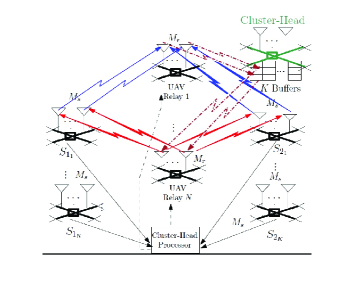
The system is a multi-way multiple-antenna Multiple-Access Broadcast-Channel (MABC) relay network composed by a number of clusters (pair of SVs and ) and half duplex (HD) decode-and-forward (DF) RVs, ,…,, where and are finite positive integer numbers and may be different from . The number of pair of SVs and the number of RVs in the UAV formation depend on the kind of mission. These SVs and RVs may be fixed-wing UAVs, that must keep a continuous progressive motion to stay aloft, or rotary-wing UAVs such as quadcopters, that can move in any direction as even as to stay stagnant in the air [2]. In a C-RAN structure, the SVs typify mobile users, the RVs typify RRHs and the UAV cluster-head typifies the cloud. The UAV cluster-head is fixed and has higher processing and buffering capacity than the other UAVs. The SVs have antennas to transmit or receive and each RV antennas, where is a finite positive integer number, all of them used for reception () and out of antennas are chosen from each RV employed for transmission (), where is a finite positive integer number and , composing a spatial multiplexing network. Therefore, the higher the superior the network performance, as it increases the degrees of freedom. Besides, the higher the superior the network performance as it increases the number of receive antennas at the RVs. Nevertheless, if and are increased, this leads to a higher computational cost. Thus, there is a trade-off between network performance and computational cost, when and are increased. The chosen RVs employ cluster-head buffers to store or extract packets in each time slot. A cluster-head buffer with size packets is used on demand for each cluster, as illustrated in Fig.1. In the uplink (MA phase), a cluster is chosen to transmit packets to a chosen RV for reception. Then, the signal is decoded by the cluster-head processor, XOR-type PLNC is performed on the decoded data and the resulting symbols are stored in their cluster-head buffers. In the downlink (BC phase), two RVs and are chosen to send packets from the particular cluster-head buffer to the chosen cluster. In most conditions the choice of only one RV in the downlink is enough for a fair performance. Nevertheless, by choosing two RVs, the chance of combining the links associated with the chosen RVs increases the degrees of freedom of the network and, thus, enhances its performance. The network could choose more than two RVs to further enhance its performance, however the computational cost would be considerably increased for a high value of . In this study, for simplicity, we employ the mRC pairwise data exchange model, but the full data exchange model may be adopted in future studies.
II-A Assumptions
The energy sent in the uplink from each SV to the chosen RV for reception () equals that transmitted in the downlink from the chosen RV(s) for transmission to the SVs (). Thus, . Non reciprocal channels and mutually independent zero mean complex Gaussian random channel coefficients, which are stationary for the time of one time slot and change independently from a time slot to another, are considered. The transmission is structured in data packets, where the order of the packets is inserted in the preamble and the primary order is recovered at the destination. Pilot symbols for estimation of channel state information (CSI) and network signaling are also inserted in the preamble. In each time slot , the central node (the UAV cluster-head) decides whether a cluster or the RVs must transmit, through a feedback channel. Global CSI at the UAV cluster-head is supplied by network signaling. Besides, each RV has information concerning its and links. The use of a UAV cluster-head as a single central node and its buffers leads to a higher control overhead. Nevertheless, it minimizes the average delay and the complexity, as a unique central node decides which nodes transmit (instead of all destination nodes) and the packets related to a cluster are stored in only its particular cluster-head buffer rather than being spread in the buffers of all RVs. This study focus on the ideal case where the fronthaul links (between the UAV cluster-head and RVs) have unconstrained capacities and RVs can reliably convey their data to the cluster-head processor. Realistic systems with capacity-constrained fronthaul links [25] may be studied in future works.
II-B System Description
Considering the worst case scenario, where UAVs can fly at ultra-low altitude (5m - 15m) and, consequently, without the presence of the Line of Sight (LoS) component (Rayleigh fading), the channel model may be aproximated to that of ground wireless sensor networks [26]. The channel matrix includes large-scale fading, arising from the path-loss of signal as a function of distance and shadowing by large objects such as buildings and hills, effects of large-scale fading, associated with the propagation parameters of the signal over far away distances, and the Rayleigh-distributed and small-scale fading effects, resulting from the constructive and destructive interference of the multiple signal paths between the transmitter and receiver [27]. Thus, the quadratic norm of is given by
| (1) |
where denotes each SV or (), refers to each RV (), is a constant determined by the carrier frequency, antenna gain and other system characteristics, is the path-loss parameter, denotes a channel matrix associated with the links modeled by mutually independent zero mean complex Gaussian random coefficients and the respective distance between and .
The same reasoning applies to and its quadratic norm is given by
| (2) |
In each time slot, the network may work in two modes: "Multiple-Access" (MA) or "Broadcast-Channel" (BC). Therefore, depending on the relay selection metrics (presented in Section III), the network has two options: a) MA mode: The chosen cluster transmits packets (one packet per each antenna) straight to the chosen RV ; and b) BC mode: and transmit packets from the cluster-head buffers to the chosen cluster. If the relay selection algorithm decides to function in the MA mode, the signal transmitted by the chosen cluster ( and ) and received at (the RV chosen for reception) is structured in an vector described by
| (3) |
where is an vector with symbols transmitted by () and other symbols transmitted by (), is a matrix of and links and is the zero mean additive white complex Gaussian noise (AWGN) at . Observe that is composed by square sub-matrices of dimensions as given by
| (4) |
Considering perfect synchronization, we employ the ML receiver at the cluster-head processor:
| (5) |
where is each of the possible vectors of transmitted symbols ( is the number of symbols in the constellation used). The ML receiver computes an estimate of the vector of symbols transmitted by the SVs . Alternative suboptimal detection techniques could also be considered in future work [29, 30, 31, 32, 33, 34, 73, 36, 37, 38, 39, 40, 41, 46, 47, 48, 49].
By performing XOR type PLNC, only the XOR outputs, that result in packets, are stored with the information: "the bit transmitted by is equal (or not) to the corresponding bit transmitted by ". Thus, the bitwise XOR is employed:
| (6) |
and the resultant symbol is stored in the cluster-head buffer. Therefore, an advantage of employing XOR is that only packets are stored in the cluster-head buffer, rather than . In contrast, if the relay selection algorithm decides to work in the BC mode, the signal transmitted by the RVs chosen for transmission ( and ) and received at and is structured in an vector given by
| (7) |
where is a vector with symbols, , , represents the matrix of and links, and is the AWGN at or . Note that is chosen among submatrices of dimensions contained in as given by
| (8) |
The ML receiver is also employed at the chosen cluster:
| (9) |
where denotes the possible vectors with symbols. Therefore, the vector of symbols sent by is calculated at by employing XOR type PLNC:
| (10) |
It is also employed at to compute the vector of symbols transmitted by :
| (11) |
An estimate is used rather than in (5) and (9) with the ML receiver for imperfect CSI. We remark that is calculated as =+, where the variance of the mutually independent zero mean complex Gaussian coefficients is described by ( and ) [15], in which in the MA phase, and in the BC phase. Channel and parameter estimation [60, 61, 62, 63, 64, 65, 66, 68, 69, 70, 71, 72, 73, 74] and resource allocation techniques [75] could be considered in future work in order to develop algorithms for this particular setting.
III Proposed CHD-Best-Link Protocol and Relay Selection Algorithm
The network in Fig. 1 employs the CHD-Best-Link protocol, which in each time slot works in the MA or BC mode. The MMD-based relay selection algorithm, when functioning, must calculate the metrics associated with different submatrices associated with the uplink channels and distinct submatrices associated with the downlink channels, where , to choose the best cluster, the best RV(s) and the mode of operation, in each time slot (high computational complexity). When a chosen cluster composed by two SVs communicates with each other, the others remain silent. Differently from [15, 16], where the MMD-based relay selection algorithm is employed for scenarios with time-uncorrelated channels and the MMD metrics are computed in each time slot, we consider scenarios where the UAVs are hovering over a specific area with low mobility, leading to possible time-correlated channels. Therefore, the MMD metrics are computed in the inicial time slot and the best RV(s) are chosen based on these metrics. Then, the MMD metrics are computed again only when it is observed that the channels have been considerably changed from the last time these metrics were computed. Thus, with the proposed recursive MMD, the MMD computation rate (number of time slots the MMD metrics are computed divided by the total number of time slots) is reduced. In the following, the protocol operation is detailed.
III-A Relay selection metric
For each cluster (with and ), in the first step, the metric related to the links of each square sub-matrix (associated with ), is calculated in the MA mode:
| (12) |
where , , and are tentative vectors with symbols and . This metric is calculated for each of the (combination of in ) possibilities, for each sub-matrix . In the second step, the ordering is performed on and the smallest metric is stored:
| (13) |
In the third step, the ordering is performed on and the largest metric is obtained:
| (14) |
where . After finding for each cluster , the ordering is performed and the largest metric is stored:
| (15) |
Therefore, the cluster and that fulfil (15) are chosen to receive packets from the chosen cluster. In the fourth step, for each cluster the metrics , related to each sub-matrix (associated with each pair and ), are computed for BC mode:
| (16) |
where , and , and , and are tentative vectors formed by symbols and . This metric is calculated for each of the possibilities, for each sub-matrix . This reasoning is also applied in the fifth step, to calculate the metric . In the sixth step, the metrics and are compared and the smallest one is stored:
| (17) |
After finding for each pair of sub-matrices and , the ordering is performed and the largest metric is obtained:
| (18) |
In the seventh step, after finding for each pair of RVs, the ordering is performed and the largest metric is stored:
| (19) |
where . After finding for each cluster , the ordering is performed and the largest metric is stored:
| (20) |
Therefore, the cluster and the RVs and that fulfil (20) are chosen to transmit at the same time packets stored in the particular cluster-head buffer to the chosen cluster. The estimated channel matrix is considered in (12) and (16), rather than , if we assume imperfect CSI.
III-B Observing the channels
At each time slot, the protocol observes if the channels change considerably in relation to the last computed MMD metrics:
| (21) |
where is the channel matrix associated with the chosen RV when the MMD metrics were computed at the last time and is the channel matrix associated with the same RV but in the present time slot. Moreover, if , in which , the protocol considers that the channels have not changed so much and decides that the last computed MMD metrics can be reused for relay selection. Otherwise, it computes again the MMD metrics, as described in Subsection III. A. Additionally, a designer might consider precoding and beamforming techniques [50, 51, 52, 53, 54, 55, 56, 57, 58, 59, 66, 67, 45, 42, 43, 44] to help mitigate interference rather than open loop transmission.
III-C Choice of the transmission mode
After calculating and (or observing the channels and deciding to reuse the last computed metrics), the metrics are compared and we choose the transmission mode:
where , is the total number of packets stored in the cluster-head buffers, is a finite integer non negative metric that when reduced increases the chance of the protocol to work in BC mode, leading to smaller average delay.
IV Analysis: Pairwise Error Probability
The PEP suposes an error event when is transmitted and the detector calculates an incorrect (where ), based on the received symbol [12, 13]. In [15, 16] an approach is proposed to analyze the PEP worst case of the Multi-Way Cloud Driven Best-User-Link (MWC-Best-User-Link) protocol. In this work, this approach is used to calculate the PEP worst case of the proposed CHD-Best-Link. Considering , in MA mode, and , in BC mode, and , an expression for computing the PEP worst case with cooperative transmissions (CT) in each time slot is described by
| (22) |
where is the smallest value of and the -function is the probability a standard normal random variable takes a value greater than its argument. The proposed CHD-Best-Link with the MMD criterion chooses the channel matrix that minimizes the PEP worst case as given by
| (23) |
This strategy can be employed for each of the square sub-matrices in a non square matrix (composed by multiple square sub-matrices). In [15], a proof shows that the MMD relay selection criterion by maximizing the minimum Euclidian distance between different vectors of transmitted symbols minimizes the BER in the ML receiver of MWC-Best-User-Link [15] and, consequently, also of CHD-Best-Link.
V Simulation Results
This section presents the simulation results of the proposed C-RAN -type CHD-Best-Link, using the recursive MMD-based relay selection algorithm, and the existing Buffer-Aided Multi-Way Max-Link (MW-Max-Link) [13] and MWC-Best-User-Link [15] protocols adapted to UAV relaying, with the MMD-based relay selection algorithm and the ML receiver. The Monte Carlo simulation method is performed. Binary Phase Shift Keying (BPSK) signals are adopted and remark that higher order constellations may be studied elsewhere. The MMD computation rate is given by the number of time slots the MMD metrics are computed divided by the total number of time slots. The time a packet takes to arrive at the destination after it is sent by the SV is considered to calculate the average delay [28]. Thus, the delay is the amount of time slots the packet resides in the buffer. These protocols were tested for a set of values and packets is enough to ensure excellent performance. Perfect and imperfect CSI and symmetric unit power channels ( ) are considered. For simplicity, homogeneous distances and path-loss are considered and the SVs and RVs are spread with distinct positions but the RVs have almost the same distances and path-loss as the SVs. Moreover, time-uncorrelated and time-correlated channels (in scenarios where the UAVs are hovering over a specific area with low mobility) are employed. With time-correlated channels, the channel matrix is described by , in each time slot, where is the channel matrix in the previous time-slot, and is also a channel matrix formed by mutually independent zero mean complex Gaussian random coefficients (with time-uncorrelated channels, ). The signal-to-noise ratio (SNR) given by ranges from 0 to 10 dB, where is the energy transmitted from each SV or the RV(s) and . The protocols were tested for packets, each containing symbols.
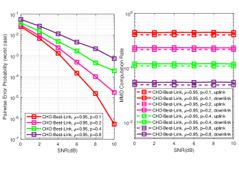
Fig. 2 illustrates the theoretical PEP worst case performance (calculated by the algorithm based on the chosen channel matrix , in each time slot) of CHD-Best-Link, for BPSK, , , , , , , perfect CSI, , 0.2, 0.4 and 0.8, (time-correlated channels). Note that the lower the value the better the PEP worst case performance and the higher the MMD computation rate (higher cost). Thus, a trade-off between PEP worst case and MMD computation rate is shown.
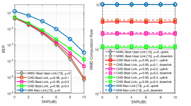
Fig. 3 depicts the BER and MMD Computation Rate of the CHD-Best-Link, MWC-Best-User-Link and MW-Max-Link protocols, for , , in MW-Max-Link and in CHD-Best-Link and MWC-Best-User-Link, , , BPSK, , perfect CSI, , 0.2 and 0.4 and and . The BER of CHD-Best-Link is quite superior to that of MW-Max-Link for all SNR values tested. Remark that the BER performance of CHD-best-Link, with , achieves a gain of approximately 3dB in SNR for the same BER as compared to that of MW-Max-Link. Besides, the BER performance of CHD-Best-Link, for and is close to that of MWC-Best-User-Link for , but with the MMD computation rate approximately of 0.2 (considerably reduced cost). Furthermore, CHD-Best-Link has the same performance of MWC-Best-User-Link [15, 16], when or , as the MMD metrics are computed in each time slot and, consequently, the MMD computation rate is equal to 1 (100%). The full and dashed curves represent the uplink and downlink MMD computation rate, repectively, which show a trade-off between BER performance and MMD computation rate.
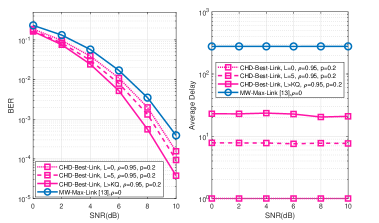
Fig. 4 depicts the BER and the average delay performances of CHD-Best-Link and MW-Max-Link, for BPSK, , , in MW-Max-Link, and in CHD-Best-Link, , , , 5 and (where ), imperfect CSI ( and ), and and 0.95. The average delay performance of CHD-Best-Link is quite supeior to that of MW-Max-Link, as CHD-Best-Link has a single group of cluster-head buffers. When the value of is reduced to 0 in CHD-Best-Link, the average delay achieves time slot, still keeping a superior BER performance to that of MW-Max-Link.
VI Conclusions
A new C-RAN -type structure with a UAV cluster-head as a central node and a recursive relay selection strategy that exploits time-correlated channels often found in UAV communications has been introduced and studied as an appropriate relay selection technique for multi-way UAV relaying schemes in FANETs. The simulation results, considering the worst case scenario (UAVs flying at ultra-low altitude) without the presence of the LoS component, show an outstanding performance of the proposed CHD-Best-Link protocol as compared to those of other existing protocols in the literature. The performance of CHD-Best-Link is considerably better than that of MW-Max-Link [13], in terms of BER, average delay and MMD computational rate (reduced complexity), and also is better than that of MWC-Best-User-Link [15], in terms of MMD computational rate. The Monte Carlo simulation method is adopted in this work, but practical experiments considering different scenarios may be performed in future studies.
References
- [1] E. Koyuncu, "Power-Efficient Deployment of UAVs as Relays", 2018, available at: https://arxiv.org/abs/1803.04315.
- [2] Zeng, R. Zhang, and T. J. Lim, ’Wireless communications with unmanned aerial vehicles: Opportunities and challenges," IEEE Commun. Mag., vol. 54, no. 5, pp. 36–42, May 2016.
- [3] H. Dai, H. Zhang, M. Hua, C. Li, Y. Huang and B. Wang, "How to Deploy Multiple UAVs for Providing Communication Service in an Unknown Region?," in IEEE Wireless Communications Letters, vol. 8, no. 4, pp. 1276-1279, Aug. 2019.
- [4] “The Multi-Objective Deployment Optimization of UAV-Mounted Cache-Enabled Base Stations,” Physical Communication, vol. 34, pp. 114-120, Jun. 2019.
- [5] H. Dai, H. Bian, C. Li and B. Wang, "UAV-Aided Wireless Communication Design With Energy Constraint in Space-Air-Ground Integrated Green IoT Networks," in IEEE Access, vol. 8, pp. 86251-86261, 2020.
- [6] G. Tuna, B. Nefzi, and G. Conte, "Unmanned aerial vehicle-aided communications system for disaster recovery," J. Network. Computer App., vol. 41, pp. 27–36, May 2014.
- [7] I. Bor-Yaliniz and H. Yanikomeroglu, "The new frontier in RAN heterogeneity: Multi-tier drone-cells," IEEE Commun. Mag., vol. 54, no. 11, pp. 48–55, Nov. 2016.
- [8] D. Liu et al., "Self-organizing relay selection in UAV communication networks: A matching game perspective," avalilable at: https://arxiv.org/abs/1805.09257
- [9] D. Liu et al., "Task-Driven Relay Assignment in Distributed UAV Communication Networks," in IEEE Trans. Veh. Tech, vol. 68, no. 11, pp. 11003-11017, Nov. 2019.
- [10] L. Gupta, R. Jain, and G. Vaszkun, "Survey of important issues in UAV communication networks, in " IEEE Commun. Surv. Tut., vol. 18, no. 2, pp. 1123–1152, Secondquarter 2016.
- [11] I. Bekmezci, O. K. Sahingoz, and S. Temel, "Flying ad-hoc networks (FANETs): A survey," Ad Hoc Netw., vol. 11, no. 3, pp. 1254–1270, May 2013.
- [12] F. L. Duarte and R. C. de Lamare, "Switched Max-Link Relay Selection Based on Maximum Minimum Distance for Cooperative MIMO Systems," IEEE Trans. Veh. Tech., vol. 69, no. 2, pp. 1928-1941, Feb. 2020.
- [13] F. L. Duarte and R. C. de Lamare, "Buffer-Aided Max-Link Relay Selection for Multi-Way Cooperative Multi-Antenna Systems," in IEEE Commun. Lett., vol. 23, no. 8, pp. 1423-1426, Aug. 2019.
- [14] D. Gunduz; A.Yener; A. Goldsmith; H. Poor, "The Multiway Relay Channel", in IEEE Trans. Inf. Theory., vol. 59, no. 1, Jan. 2013.
- [15] F. L. Duarte and R. C. de Lamare, "Cloud-Driven Multi-Way Multiple-Antenna Relay Systems: Joint Detection, Best-User-Link Selection and Analysis," IEEE Trans. Comm., 2020.
- [16] F. L. Duarte and R. C. de Lamare, “Cloud-Aided Multi-Way Multiple-Antenna Relaying with Best-User Link Selection and Joint ML Detection" in 24th Int. ITG Workshop on Smart Antennas (WSA 2020), Hamburg, Germany, 2020.
- [17] F. L. Duarte and R. C. de Lamare, "Cloud-Driven Multi-Way Multiple-Antenna Relay Systems: Best-User-Link Selection and Joint Mmse Detection," ICASSP 2020 - 2020 IEEE Int. Conf. on Acoustics, Speech and Sign. Processing (ICASSP), Barcelona, Spain, 2020, pp. 5160-5164.
- [18] I. Krikidis, T. Charalambous, and J. Thompson, “Buffer-Aided Relay Selection for Cooperative Diversity Systems Without Delay Constraints,” IEEE Trans. Wireless Commun., vol. 11, no. 5, pp. 1957–1967, May 2012.
- [19] I. Krikidis, "Relay Selection for Two-Way Relay Channels With MABC DF: A Diversity Perspective," in IEEE Trans. Veh. Tech., vol. 59, no. 9, pp. 4620-4628, Nov. 2010.
- [20] P. Clarke and R. C. de Lamare, “Joint Transmit Diversity Optimization and Relay Selection for Multi-Relay Cooperative MIMO Systems Using Discrete Stochastic Algorithms," IEEE Communications Letters, vol. 15, no. 10, pp. 1035-1037, October 2011.
- [21] P. Clarke and R. C. de Lamare, "Transmit Diversity and Relay Selection Algorithms for Multirelay Cooperative MIMO Systems," in IEEE Trans. Veh. Tech., vol. 61, no. 3, pp. 1084-1098, March 2012.
- [22] T. Peng, R. C. de Lamare and A. Schmeink, “Adaptive Distributed Space-Time Coding Based on Adjustable Code Matrices for Cooperative MIMO Relaying Systems," IEEE Transactions on Communications, vol. 61, no. 7, pp. 2692-2703, July 2013.
- [23] T. Peng and R. C. de Lamare, “Adaptive Buffer-Aided Distributed Space-Time Coding for Cooperative Wireless Networks," IEEE Transactions on Communications, vol. 64, no. 5, pp. 1888-1900, May 2016.
- [24] J. Gu, R. C. de Lamare and M. Huemer, "Buffer-Aided Physical-Layer Network Coding With Optimal Linear Code Designs for Cooperative Networks," in IEEE Trans. Commun., vol. 66, no. 6, pp. 2560-2575, June 2018.
- [25] T. Q. S. Quek, M. Peng, O. Simeone, and W. Yu, Eds., "Cloud Radio Access Networks: Principles, Technologies, and Applications". Cambridge Univ. Press, Feb. 2017.
- [26] F. Engel, T. Abrão and L. Hanzo, "Relay selection methods for maximizing the lifetime of wireless sensor networks," 2013 IEEE Wireless Commun. and Netw. Conf. (WCNC), Shanghai, 2013, pp. 2339-2344.
- [27] C. Yan, L. Fu, J. Zhang and J. Wang, "A Comprehensive Survey on UAV Communication Channel Modeling," in IEEE Access, vol. 7, pp. 107769-107792, 2019.
- [28] D. Poulimeneas, T. Charalambous, N. Nomikos, I. Krikidis, D. Vouyioukas and M. Johansson, "Delay- and diversity-aware buffer-aided relay selection policies in cooperative networks," 2016 IEEE Wireless Commun. and Netw. Conf., Doha, 2016, pp. 1-6.
- [29] R. C. de Lamare, "Massive MIMO systems: Signal processing challenges and future trends," in URSI Radio Science Bulletin, vol. 2013, no. 347, pp. 8-20, Dec. 2013.
- [30] W. Zhang et al., "Large-Scale Antenna Systems With UL/DL Hardware Mismatch: Achievable Rates Analysis and Calibration," in IEEE Transactions on Communications, vol. 63, no. 4, pp. 1216-1229, April 2015.
- [31] R. C. de Lamare and R. Sampaio-Neto, "Adaptive MBER decision feedback multiuser receivers in frequency selective fading channels," in IEEE Communications Letters, vol. 7, no. 2, pp. 73-75, Feb. 2003.
- [32] R. C. De Lamare, R. Sampaio-Neto and A. Hjorungnes, "Joint iterative interference cancellation and parameter estimation for cdma systems," in IEEE Communications Letters, vol. 11, no. 12, pp. 916-918, December 2007.
- [33] R. C. De Lamare and R. Sampaio-Neto, “Minimum Mean-Squared Error Iterative Successive Parallel Arbitrated Decision Feedback Detectors for DS-CDMA Systems,” in IEEE Transactions on Communications, vol. 56, no. 5, pp. 778-789, May 2008.
- [34] Y. Cai and R. C. de Lamare, "Space-Time Adaptive MMSE Multiuser Decision Feedback Detectors With Multiple-Feedback Interference Cancellation for CDMA Systems," in IEEE Transactions on Vehicular Technology, vol. 58, no. 8, pp. 4129-4140, Oct. 2009.
- [35] R. C. de Lamare and R. Sampaio-Neto, "Adaptive Reduced-Rank Equalization Algorithms Based on Alternating Optimization Design Techniques for MIMO Systems," in IEEE Transactions on Vehicular Technology, vol. 60, no. 6, pp. 2482-2494, July 2011.
- [36] P. Li, R. C. de Lamare and R. Fa, “Multiple Feedback Successive Interference Cancellation Detection for Multiuser MIMO Systems,” in IEEE Trans. on Wireless Comm., vol. 10, no. 8, pp. 2434-2439, Aug. 2011.
- [37] N. Song, R. C. de Lamare, M. Haardt and M. Wolf, "Adaptive Widely Linear Reduced-Rank Interference Suppression Based on the Multistage Wiener Filter," in IEEE Transactions on Signal Processing, vol. 60, no. 8, pp. 4003-4016, Aug. 2012.
- [38] P. Li and R. C. De Lamare, "Adaptive Decision-Feedback Detection With Constellation Constraints for MIMO Systems," in IEEE Transactions on Vehicular Technology, vol. 61, no. 2, pp. 853-859, Feb. 2012.
- [39] R. C. de Lamare, “Adaptive and Iterative Multi-Branch MMSE Decision Feedback Detection Algorithms for Multi-Antenna Systems,” in IEEE Transactions on Wireless Communications, vol. 12, no. 10, pp. 5294-5308, October 2013.
- [40] P. Li and R. C. de Lamare, "Distributed Iterative Detection With Reduced Message Passing for Networked MIMO Cellular Systems," in IEEE Transactions on Vehicular Technology, vol. 63, no. 6, pp. 2947-2954, July 2014.
- [41] Y. Cai, R. C. de Lamare, B. Champagne, B. Qin and M. Zhao, "Adaptive Reduced-Rank Receive Processing Based on Minimum Symbol-Error-Rate Criterion for Large-Scale Multiple-Antenna Systems," in IEEE Transactions on Communications, vol. 63, no. 11, pp. 4185-4201, Nov. 2015.
- [42] H. Ruan and R. C. de Lamare, "Robust Adaptive Beamforming Using a Low-Complexity Shrinkage-Based Mismatch Estimation Algorithm," IEEE Signal Processing Letters, vol. 21, no. 1, pp. 60-64, Jan. 2014.
- [43] H. Ruan and R. C. de Lamare, "Robust Adaptive Beamforming Based on Low-Rank and Cross-Correlation Techniques," IEEE Transactions on Signal Processing, vol. 64, no. 15, pp. 3919-3932, 1 Aug.1, 2016.
- [44] H. Ruan and R. C. de Lamare, "Distributed Robust Beamforming Based on Low-Rank and Cross-Correlation Techniques: Design and Analysis," in IEEE Transactions on Signal Processing, vol. 67, no. 24, pp. 6411-6423, 15 Dec.15, 2019.
- [45] N. Song, W. U. Alokozai, R. C. de Lamare and M. Haardt, "Adaptive Widely Linear Reduced-Rank Beamforming Based on Joint Iterative Optimization," in IEEE Signal Processing Letters, vol. 21, no. 3, pp. 265-269, March 2014.
- [46] A. G. D. Uchoa, C. T. Healy and R. C. de Lamare, "Iterative Detection and Decoding Algorithms for MIMO Systems in Block-Fading Channels Using LDPC Codes," in IEEE Transactions on Vehicular Technology, vol. 65, no. 4, pp. 2735-2741, April 2016.
- [47] Z. Shao, R. C. de Lamare and L. T. N. Landau, "Iterative Detection and Decoding for Large-Scale Multiple-Antenna Systems With 1-Bit ADCs," in IEEE Wireless Communications Letters, vol. 7, no. 3, pp. 476-479, June 2018.
- [48] R. B. Di Renna and R. C. de Lamare, “Adaptive Activity-Aware Iterative Detection for Massive Machine-Type Communications," IEEE Wireless Communications Letters, vol. 8, no. 6, pp. 1631-1634, Dec. 2019.
- [49] R. B. D. Renna and R. C. D. Lamare, “Iterative List Detection and Decoding for Massive Machine-Type Communications," IEEE Transactions on Communications, 2020.
- [50] K. Zu and R. C. de Lamare, "Low-Complexity Lattice Reduction-Aided Regularized Block Diagonalization for MU-MIMO Systems," in IEEE Communications Letters, vol. 16, no. 6, pp. 925-928, June 2012.
- [51] Y. Cai, R. C. de Lamare, and R. Fa, “Switched Interleaving Techniques with Limited Feedback for Interference Mitigation in DS-CDMA Systems," IEEE Transactions on Communications, vol.59, no.7, pp.1946-1956, July 2011.
- [52] Y. Cai, R. C. de Lamare, D. Le Ruyet, “Transmit Processing Techniques Based on Switched Interleaving and Limited Feedback for Interference Mitigation in Multiantenna MC-CDMA Systems," IEEE Transactions on Vehicular Technology, vol.60, no.4, pp.1559-1570, May 2011.
- [53] K. Zu, R. C. de Lamare and M. Haardt, "Generalized Design of Low-Complexity Block Diagonalization Type Precoding Algorithms for Multiuser MIMO Systems," IEEE Transactions on Communications, vol. 61, no. 10, pp. 4232-4242, October 2013.
- [54] W. Zhang et al., "Widely Linear Precoding for Large-Scale MIMO with IQI: Algorithms and Performance Analysis," IEEE Transactions on Wireless Communications, vol. 16, no. 5, pp. 3298-3312, May 2017.
- [55] K. Zu, R. C. de Lamare and M. Haardt, "Multi-Branch Tomlinson-Harashima Precoding Design for MU-MIMO Systems: Theory and Algorithms," IEEE Transactions on Communications, vol. 62, no. 3, pp. 939-951, March 2014.
- [56] L. Zhang, Y. Cai, R. C. de Lamare and M. Zhao, "Robust Multibranch Tomlinson-Harashima Precoding Design in Amplify-and-Forward MIMO Relay Systems," IEEE Transactions on Communications, vol. 62, no. 10, pp. 3476-3490, Oct. 2014.
- [57] L. T. N. Landau and R. C. de Lamare, "Branch-and-Bound Precoding for Multiuser MIMO Systems With 1-Bit Quantization," in IEEE Wireless Communications Letters, vol. 6, no. 6, pp. 770-773, Dec. 2017.
- [58] L. T. N. Landau, M. Dorpinghaus, R. C. de Lamare and G. P. Fettweis, "Achievable Rate With 1-Bit Quantization and Oversampling Using Continuous Phase Modulation-Based Sequences," in IEEE Transactions on Wireless Communications, vol. 17, no. 10, pp. 7080-7095, Oct. 2018.
- [59] A. R. Flores, R. C. de Lamare and B. Clerckx, "Linear Precoding and Stream Combining for Rate Splitting in Multiuser MIMO Systems," in IEEE Communications Letters, vol. 24, no. 4, pp. 890-894, April 2020.
- [60] T. Wang, R. C. de Lamare, and P. D. Mitchell, “Low-Complexity Set-Membership Channel Estimation for Cooperative Wireless Sensor Networks," IEEE Transactions on Vehicular Technology, vol.60, no.6, pp.2594-2607, July 2011.
- [61] Z. Shao, L. T. N. Landau and R. C. De Lamare, “Channel Estimation for Large-Scale Multiple-Antenna Systems Using 1-Bit ADCs and Oversampling," IEEE Access, vol. 8, pp. 85243-85256, 2020.
- [62] T. Wang, R. C. de Lamare and A. Schmeink, "Joint linear receiver design and power allocation using alternating optimization algorithms for wireless sensor networks," IEEE Trans. on Vehi. Tech., vol. 61, pp. 4129-4141, 2012.
- [63] R. C. de Lamare, “Joint iterative power allocation and linear interference suppression algorithms for cooperative DS-CDMA networks", IET Communications, vol. 6, no. 13 , 2012, pp. 1930-1942.
- [64] T. Peng, R. C. de Lamare and A. Schmeink, “Adaptive Distributed Space-Time Coding Based on Adjustable Code Matrices for Cooperative MIMO Relaying Systems”, IEEE Transactions on Communications, vol. 61, no. 7, July 2013.
- [65] T. Peng and R. C. de Lamare, “Adaptive Buffer-Aided Distributed Space-Time Coding for Cooperative Wireless Networks," IEEE Transactions on Communications, vol. 64, no. 5, pp. 1888-1900, May 2016.
- [66] J. Gu, R. C. de Lamare and M. Huemer, “Buffer-Aided Physical-Layer Network Coding with Optimal Linear Code Designs for Cooperative Networks," IEEE Transactions on Communications, 2018.
- [67] C. T. Healy and R. C. de Lamare, "Design of LDPC Codes Based on Multipath EMD Strategies for Progressive Edge Growth," IEEE Transactions on Communications, vol. 64, no. 8, pp. 3208-3219, Aug. 2016.
- [68] M. L. Honig and J. S. Goldstein, “Adaptive reduced-rank interference suppression based on the multistage Wiener filter," IEEE Transactions on Communications, vol. 50, no. 6, June 2002.
- [69] Q. Haoli and S.N. Batalama, “Data record-based criteria for the selection of an auxiliary vector estimator of the MMSE/MVDR filter", IEEE Transactions on Communications, vol. 51, no. 10, Oct. 2003, pp. 1700 - 1708.
- [70] R. C. de Lamare and R. Sampaio-Neto, “Reduced-Rank Adaptive Filtering Based on Joint Iterative Optimization of Adaptive Filters", IEEE Signal Processing Letters, Vol. 14, no. 12, December 2007.
- [71] R. C. de Lamare and R. Sampaio-Neto, “Adaptive Reduced-Rank Processing Based on Joint and Iterative Interpolation, Decimation and Filtering", IEEE Transactions on Signal Processing, vol. 57, no. 7, July 2009, pp. 2503 - 2514.
- [72] R. C. de Lamare and R. Sampaio-Neto, “Reduced-rank space-time adaptive interference suppression with joint iterative least squares algorithms for spread-spectrum systems," IEEE Trans. Vehi. Technol., vol. 59, no. 3, pp. 1217-1228, Mar. 2010.
- [73] R. C. de Lamare and R. Sampaio-Neto, “Adaptive reduced-rank equalization algorithms based on alternating optimization design techniques for MIMO systems," IEEE Trans. Vehi. Technol., vol. 60, no. 6, pp. 2482-2494, Jul. 2011.
- [74] S. Xu, R. C. de Lamare and H. V. Poor, "Distributed Compressed Estimation Based on Compressive Sensing," IEEE Signal Processing Letters, vol. 22, no. 9, pp. 1311-1315, Sept. 2015.
- [75] Y. Jiang et al., "Joint Power and Bandwidth Allocation for Energy-Efficient Heterogeneous Cellular Networks," in IEEE Transactions on Communications, vol. 67, no. 9, pp. 6168-6178, Sept. 2019.