High-Frequency Gravitational-Wave Detection Using a Chiral Resonant Mechanical Element and a Short Unstable Optical Cavity
Abstract
Present gravitational wave detectors are based on the measurement of linear displacement in stable optical cavities. Here, we instead suggest the measurement of the twist of a chiral mechanical element induced by a gravitational wave. The induced twist rotates a flat optical mirror on top of this chiral element, leading to the deflection of an incident laser beam. This angle change is enhanced by multiple bounces of light between the rotating mirror and an originally parallel nearby fixed flat mirror. Based on detailed continuum-mechanics calculations, we present a feasible design for the chiral mechanical element including the rotating mirror. Our approach is most useful for signals in the frequency band – where we show that fundamental metrological limits would allow for smaller shot noise in this setup in comparison to the detection of linear displacement. We estimate a gravitational wave strain sensitivity between and at around frequency. When appropriately scaling the involved geometrical parameters, the strain sensitivity is proportional to frequency.
pacs:
62.20.−x,62.65.+kThe discovery of gravitational waves Einstein (1916) by LIGO Abbott et al. (2016a, b, 2017a, 2017b) has opened a new window into the universe. LIGO attains its peak sensitivity around Aasi et al. (2015), enabling it to detect the mergers of binary black holes that have masses . There is a strong physics case to probe gravitational waves at higher frequencies ( – ) where one might observe mergers of smaller () black holes, while also being able to search for the full spectrum Kaplan and Rajendran (2019) of quasinormal modes from the ringdown of a merger observed in LIGO. In addition to these standard astrophysical signatures, detectors in this frequency band will also be sensitive to gravitational waves produced from the high temperature ( PeV) universe and from new physics such as super-radiant bosonic clouds around black holes Arvanitaki et al. (2010). Simultaneously, these detectors can search for a variety of ultra-light dark matter Ranjit et al. (2016); Graham et al. (2016); Arvanitaki et al. (2018).
The fundamental difficulty in probing these higher frequencies arises from the fact that the shorter period reduces the time available for the signal to cause a measurable change (i.e., beat shot noise) in an experiment, diminishing the sensitivity of a LIGO-style stable optical cavity at these frequencies. In this Letter, we point out that the shot noise limit on sensitivity can be improved by measuring angular displacement in an unstable optical cavity as opposed to measuring linear displacement in a stable cavity. This sensitivity gain can only be attained if other sources of noise (such as thermal noise) are suppressed and if the quality factor of the cavity is sufficiently large. Due to the rapid scaling of event rates in gravitational wave detectors with sensitivity, even modest improvements in sensitivity lead to significant scientific payoff.
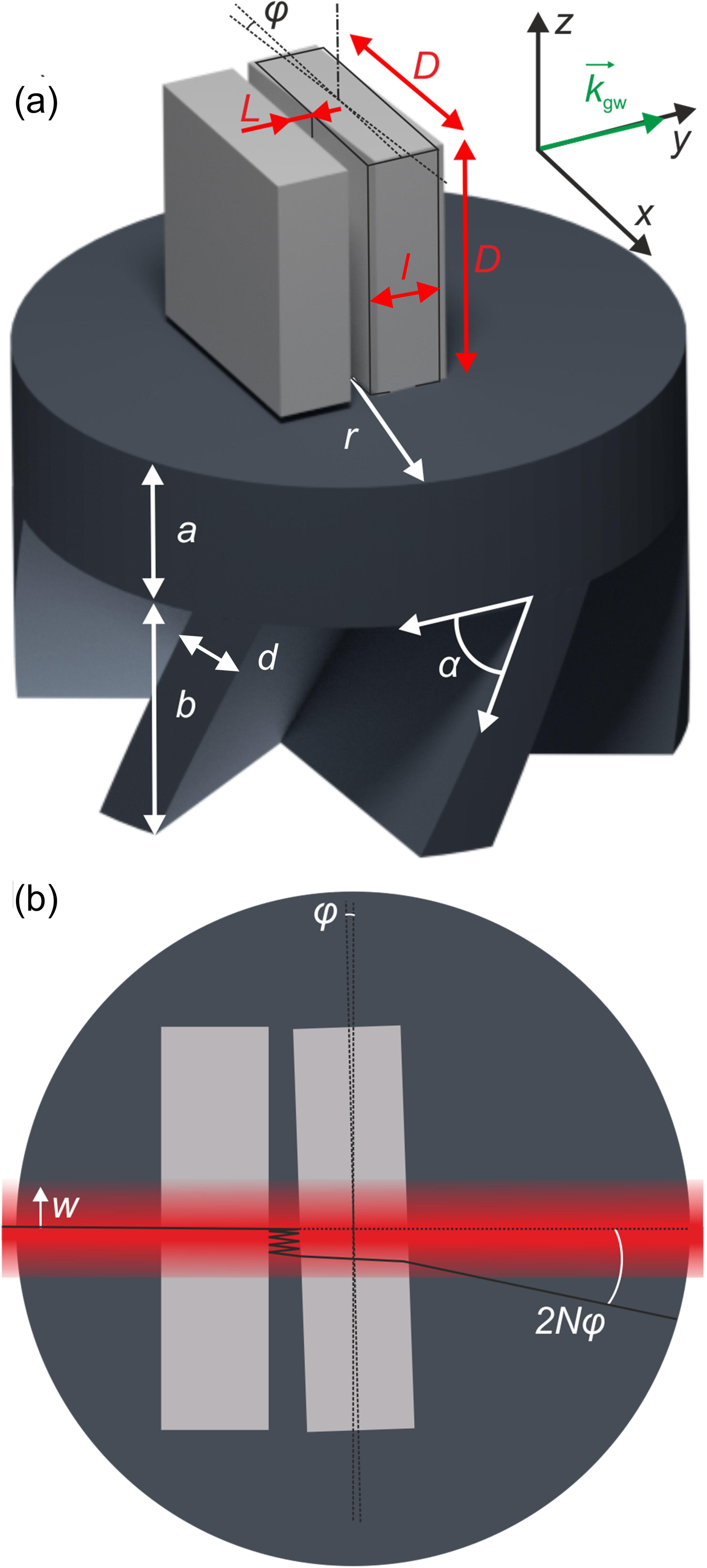
Our idea starts from converting an axial gravitational strain into a twist or rotation, which has been discussed in the context of chiral mechanical metamaterialsFrenzel et al. (2017); Fernandez-Corbaton et al. (2019); Chen et al. (2020). As shown in Fig. 1, the detection principle of our detector is to measure the gravitational strain by monitoring the angle of a laser beam that is reflected by a mirror that is rotated by the induced twist. The strain-to-twist conversion factor, , can be boosted in the vicinity of a high-quality-factor mechanical resonance. As illustrated in Fig. 1(b), the magnitude of the deflection angle can be increased by multiple round trips of light between two flat mirrors, Hogan et al. (2011). To reduce shot noise by reducing the diffraction limit on measuring this angle, the diameter of the beam and hence the size of the rotating mirror need to be as large as possible. However, large size corresponds to large mass, which reduces the resonance frequency unless the torsional stiffness of the chiral mechanical element can be made very large. Furthermore, the chiral torsional mechanical eigenmode should ideally correspond to the lowest mechanical eigenfrequency of the overall setup. Otherwise, deformations other than a pure rotation of the mirror may become increasingly important. For example, a warping of the previously flat mirror surface would lead to an unwanted distortion of the laser beam profile. Altogether, this means that the design of the resonant chiral mechanical element results from a non-trivial trade-off.
To investigate the elastic behavior of the chiral mechanical element shown in Fig. 1(a) under the influence of a gravitational wave impinging along the -direction, we solve Newton’s second law combined with Hooke’s law, cast into linear Cauchy continuum mechanics for the position and time-dependent displacement vector given by
| (1) |
is the local mass density, the rank-2 stress tensor, given by the contraction ”:” of the rank-4 Cauchy elasticity tensor and the rank-2 strain tensor , and is the gravitational-wave acceleration vector. represents a body-force density Misner et al. (1973) and is given by
| (2) |
with the gravitational-wave strain matrix at angular frequency
| (3) |
The reference coordinate can be chosen arbitrarily, e.g., as the center of mass of the setup, which includes a large cuboid plate underneath the chiral element shown in Fig. 1(a). is the dimensionless strain amplitude of the gravitational wave. The dispersion relation is , with the vacuum speed of light . We approximate the wave number as , which is justified if the wavelength of the gravitational wave, , is large compared to the size of the setup shown in Fig. 1. For the frequency chosen below, we have and this approximation is well justified. The above equations are solved numerically by standard frequency-domain finite-element calculations using the software package Comsol Multiphysics Hughes (2000) and its MUMPS solver. The geometrical parameters are given in Fig. 1. For the material parameters, we choose an isotropic (polycrystalline) version of diamond Ashby (2011), with a Young’s modulus of , a loss tangent of , a Poisson’s ratio of , and a mass density of . Diamond serves as a benchmark in the sense that it exhibits the largest transverse and longitudinal phonon phase velocities of all known natural materials. In essence, the phonon phase velocities combined with the geometrical parameters determine the mechanical eigenfrequencies of the system.
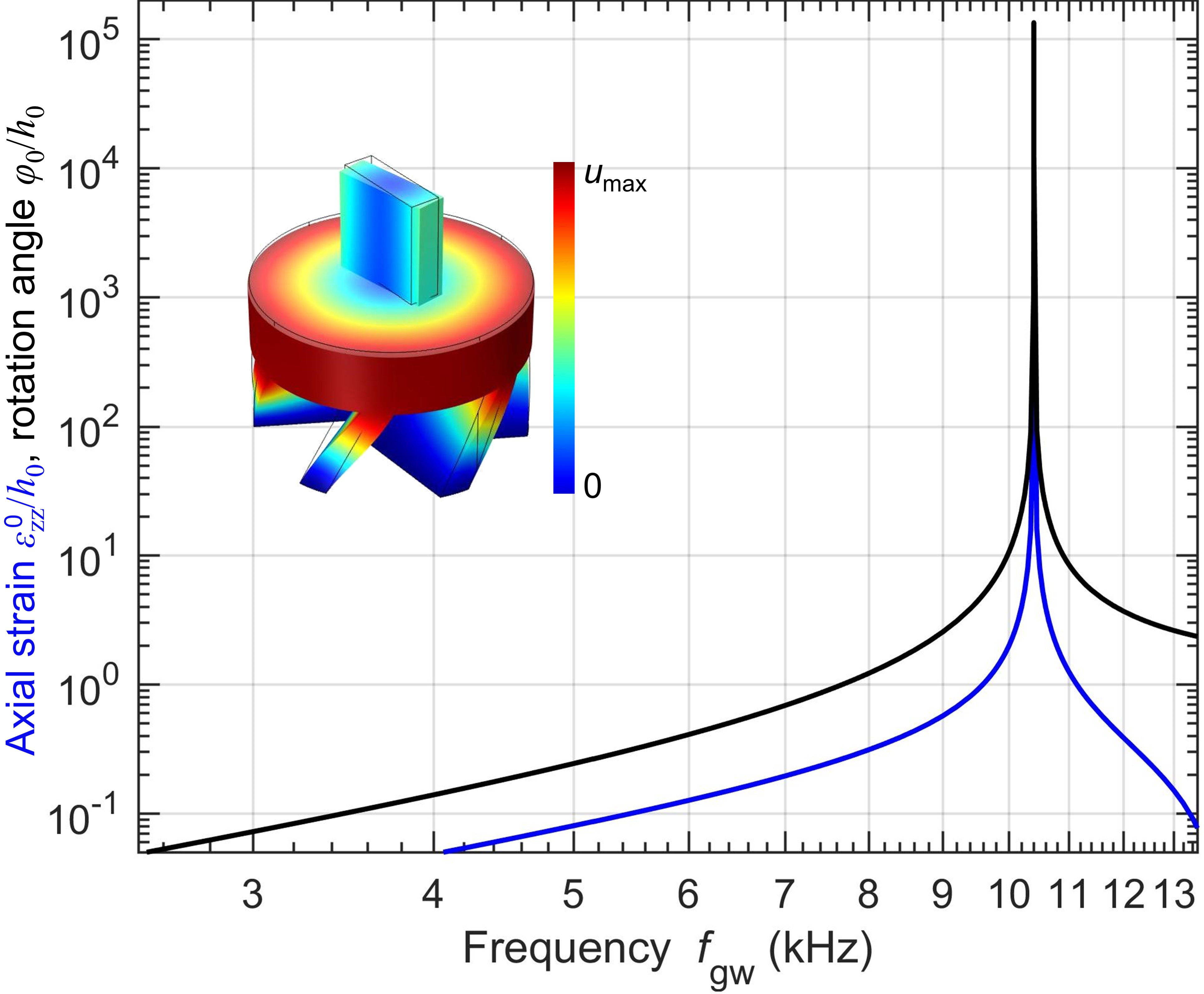
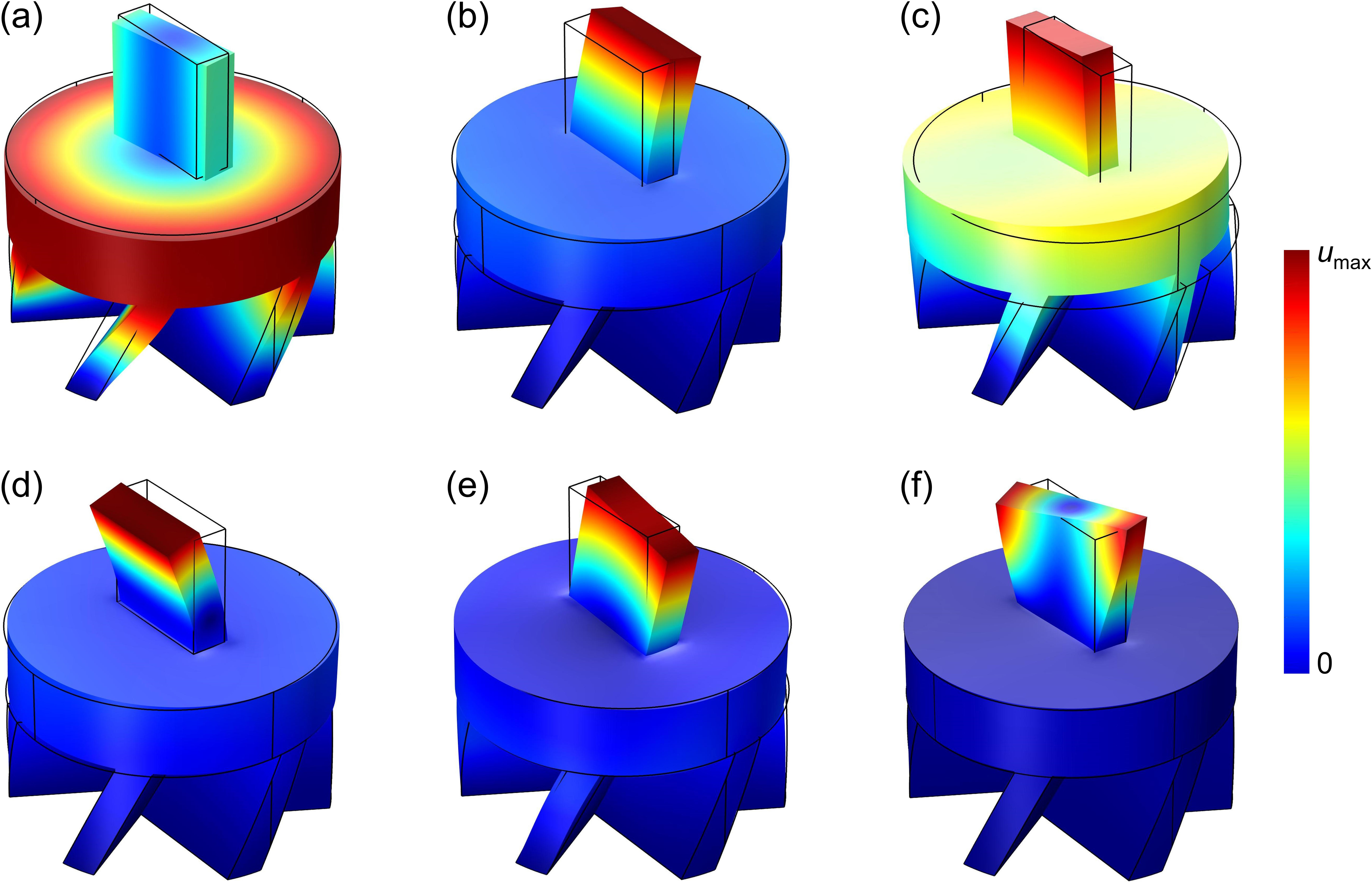
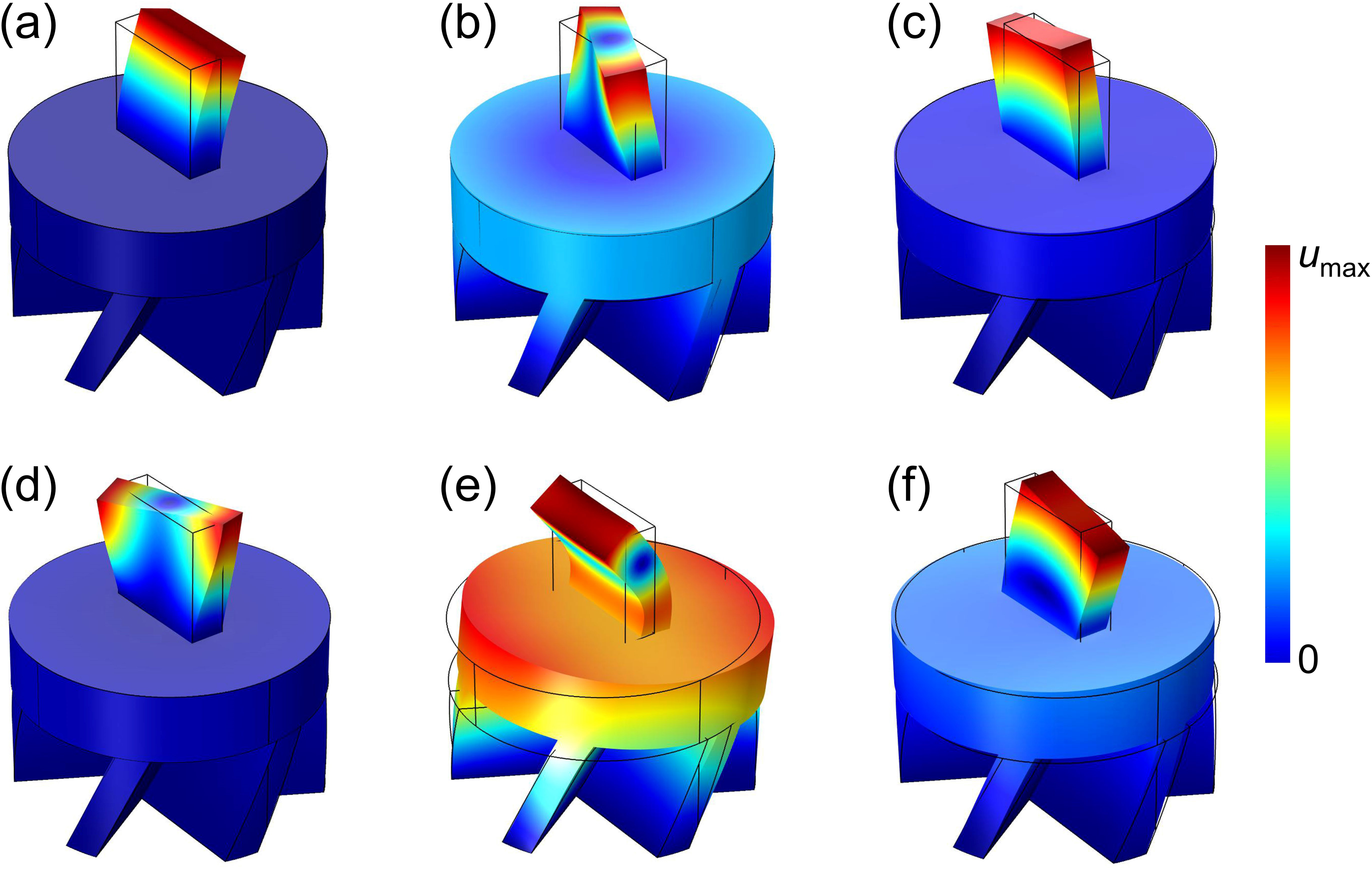
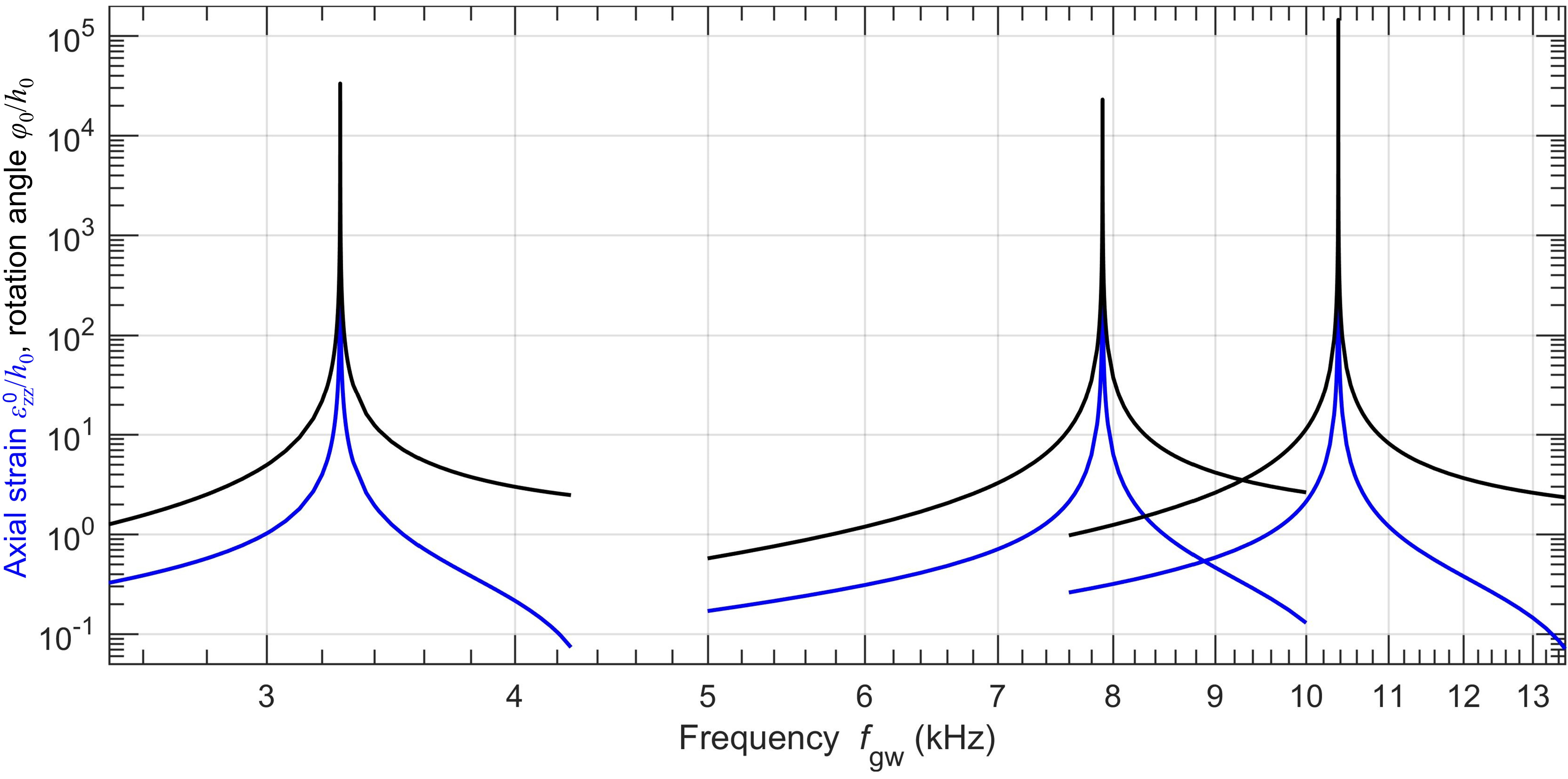
The system in Fig. 1 reacts with a time-harmonic twist angle and a time-harmonic axial strain . An example response function of the twist angle amplitude and the axial strain amplitude versus frequency is depicted in Fig. 2. Its vertical axis is normalized with respect to the dimensionless gravitational-wave strain amplitude . The axial strain amplitude is dimensionless, the twist angle amplitude is in units of radians. On resonance, it reaches a maximum of . For a mirror mount with a size of in Fig. 1, the lowest eigenfrequency of the overall setup lies at around . It is clear that working close to a mechanical eigenfrequency means that the bandwidth of the gravitational wave detector becomes small. Below the resonance frequency, the response increases because the body-force density is proportional to the second temporal derivative of . To provide a broader overview of the behavior, the six lowest-frequency eigenmodes of the system are shown in Fig. S1 PRLSupp .
The example shown in Fig. 2 can easily be scaled to other sizes provided that all aspect ratios are fixed and that the material parameters are fixed. For example, when increasing (decreasing) all geometrical parameters given in Fig. 1 by a factor of ten, the frequencies on the horizontal axis of Fig. 2 need to be scaled down (up) by a factor of ten, while the vertical axis remains unchanged.
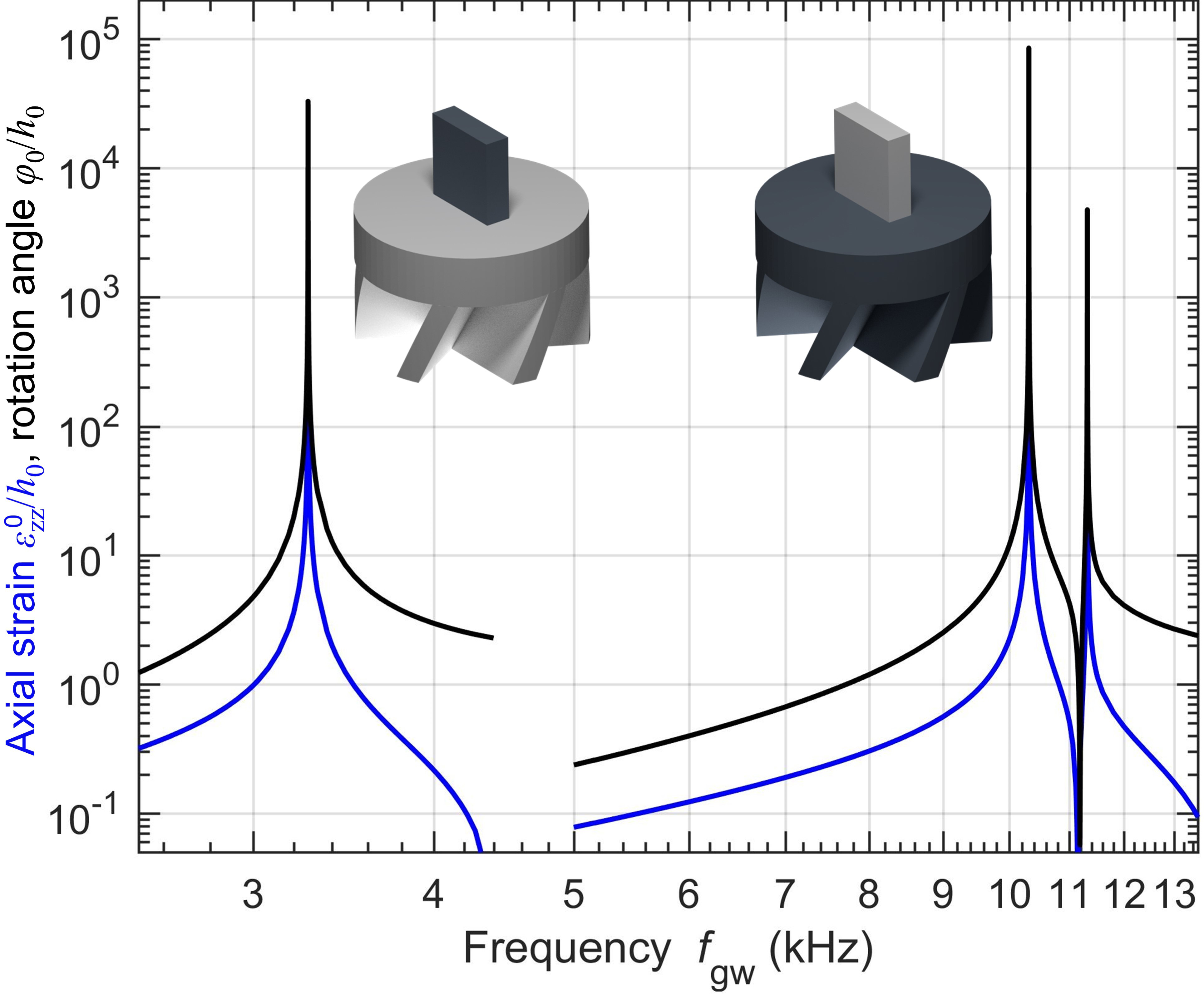
Results for hybrid materials choices are shown in Fig. 3. For example, when replacing the diamond mirror substrate at the top by silica (), while keeping the diamond bottom, unwanted deformations of the mirror become much more prominent as the mirror can no longer be approximately considered as a rigid body (c.f. Fig. S2 PRLSupp ). When going to the reverse hybrid structure of silica bottom and diamond top, the mirror rotates rigidly but the twist eigenfrequency decreases. On the other hand, hybrid architectures containing materials choices other than diamond are more accessible experimentally in terms of manufacturing and cost. Refer to Fig. S3 for other material combinations PRLSupp .
Next, we estimate the gravitational-wave strain sensitivity achievable with the calculated (frequency-dependent) rotation angle amplitude
| (4) |
with the frequency dependent strain-to-twist conversion factor, . We consider an optical cavity of length composed of the rotating mirror and a second fixed mirror of the same size as shown in Fig. 1(b). The two mirrors are flat and originally parallel, representing an unstable optical resonator on the level of wave optics Koechner (2006). A Gaussian laser beam with a intensity radius impinges under normal incidence and is reflected by the mirrors times, with the mean number of round trips of light in the cavity, . In geometrical optics and for rotation angle , normal incidence of light leads to a mean deflection angle of (as illustrated in Fig. 1(b)). Normal incidence of light with a sufficiently small error is important: To avoid that the beam walks off the edge of the mirror, the incidence angle of the laser beam with respect to the mirror surface normal must obey the condition . For , , and (see below), this condition leads to (i.e., degrees), which appears feasible. The parallelism of the two flat mirrors must be aligned with a comparable precision.
To achieve a large mean deflection angle , large integers are clearly desirable. However, the product is bounded by the fact that the dwell time of light between the two mirrors must not be larger than half of the gravitational wave temporal period . Otherwise, the sign of the gravitational strain flips during the accumulation and the accumulated angle decreases again. This condition leads to the dwell-time inequality
| (5) |
For example, for , we obtain . With, e.g., this leads to .
An independent bound for the product arises from the fact that an incident Gaussian beam focused to an intensity radius at free-space optical wavelength unavoidably diverges by diffraction of light when propagating over distance . However, this divergence is negligibly small provided that is much smaller than the Rayleigh range Koechner (2006), i.e.,
| (6) |
For example, for and , we get . With , this leads to . Clearly, for these parameters, this bound on is more than two orders of magnitude more stringent than the above dwell-time bound. For our choice of and , the dwell-time inequality is fulfilled as long as . This means that the deflection angle well approximates the instantaneous gravitational wave strain for .
Achieving a value of requires sufficiently high optical mirror reflectivity by using high-quality dielectric Bragg stacks. It also requires that the mirror size is sufficiently large compared to the intensity Gaussian beam radius to avoid cut-off losses. For example, for , the Gaussian intensity profile on the edge of the mirror decreases to of the center value (cf. Fig. 1(b)).
To measure the angular deflection, the emerging Gaussian laser beam could be focused Saleh and Teich (2019) by a lens of focal length to a Gaussian spot of intensity focus radius
| (7) |
This focus radius is connected to the standard deviation, , of the focus position via . The localization error of the focus position (or standard deviation of the mean value) for the rate of photons emerging from the cavity, , is given by
| (8) |
We assume that we operate on a Fabry-Perot resonance, where the optical transmittance is unity and equals the rate of photons of the incident laser. Finally, the focus displacement, , due to the mean deflection angle is given by . The minimum detectable gravitational strain amplitude corresponds to . Insertion of the above equations leads to the gravitational-wave strain sensitivity
| (9) |
Here, the focal length has dropped out, which means that one can choose an experimentally convenient focal length for the displacement measurement.
The estimate (9) contains two aspects that are conceptually different from mechanical off-resonant hence broadband interferometric gravitational-wave detection. First, the factor stems from the resonant mechanical strain-to-twist enhancement discussed in Fig. 2. This mechanism enhances the gravitational-wave induced strain, environmental noise, and thermal fluctuations alike. Thermal fluctuation can be estimated from Eq. (16) in Saulson (1990). For example, for the parameters given in Fig. 1, we have the mechanical quality factor , the axial stiffness , the mass , the height and the eigenfrequency , leading to a strain of at a temperature of . Other sources of thermodynamic noise Braginsky et al. (1999) are subdominant. The device needs to be suitably decoupled from environmental noise. Furthermore, reducing technical noise on the angle of the incident laser beam is critical. Second, the factor can be seen as a lever-arm effect of the optical cavity resulting from the angle detection scheme. For the parameters considered above, the accessible number of round trips in the cavity is essentially limited by diffraction of light. In the regime where the maximum is rather determined by the dwell-time bound (5), the strain sensitivity of our setup scales , whereas that of a linear interferometer scales , and thus our setup could potentially lead to a sensitivity gain .
As a conservative example, the parameters , , , (compare Fig. 2 with peak enhancement ), and , hence optical power, lead to the gravitational-wave strain-sensitivity estimate of
| (10) |
at around frequency. From above, we additionally have and (cf. Fig. 1). To scale our detector to ten times higher (lower) frequencies, the geometrical parameters shown in Fig. 1 and the beam radius can be decreased (increased) tenfold, while adjusting the product according to (6). In this case, for fixed , the strain sensitivity scales proportional to frequency. Towards lower frequencies, the sensitivity could alternatively be improved by fixing and increasing .
In conclusion, we have proposed a novel compact approach for detecting gravitational waves at frequencies in the range of – . A resonant chiral mechanical element converts a gravitational-wave strain into the rotation of one flat end mirror of a short unstable optical Fabry-Perot cavity. The unstable optical cavity enhances the deflection angle by multiple bounces of light within. Important parameters include the laser power , the mean number of round trips in the cavity , and the mechanical enhancement factor . For laser power at wavelength, beam radius, , and , we have estimated a gravitational-wave strain sensitivity of better than in a bandwidth of about at around frequency. Using somewhat more optimistic parameters of, e.g., , , and , the theoretical sensitivity estimate improves to . Using a smaller laser wavelength would further improve the behavior. For comparison, LIGO has achieved experimentally a squeezed-states-of-light enhanced sensitivity of about at around frequency Aasi et al. (2013).
I Supplemental Materials
I.1 Eigenmodes of the chiral mechanical system
See figure 5.
I.2 Calculated response of the chiral mechanical system for other material combinations
See figure 6.
II Acknowledgments
We acknowledge discussions with Dima Budker (University of Mainz), Jason Hogan (Stanford University) as well as with Andreas Naber, Tobias Frenzel, and Julian Köpfler (all KIT). Y.C. acknowledges support by the Alexander von Humboldt foundation and by the National Natural Science Foundation of China (contract No. 11802017). This research has additionally been funded by the Deutsche Forschungsgemeinschaft (DFG, German Research Foundation) under Germany’s Excellence Strategy via the Excellence Cluster “3D Matter Made to Order” (EXC-2082/1-390761711), which has also been supported by the Carl Zeiss Foundation through the “Carl-Zeiss-Foundation-Focus@HEiKA”, by the State of Baden-Württemberg, and by the Karlsruhe Institute of Technology (KIT). We further acknowledge support by the Helmholtz program “Science and Technology of Nanosystems” (STN), and by the associated KIT project “Virtual Materials Design” (VIRTMAT). M.K. is grateful for support by the EIPHI Graduate School (contract No. ANR-17-EURE-0002) and by the French Investissements d’Avenir program, project ISITEBFC (contract No. ANR-15-IDEX-03). D.E.K. and S.R. are supported by the US National Science Foundation (contract No. PHY-1818899). S.R. is also supported by the DoE under a QuantISED grant for MAGIS. A.O.S. is supported by the US National Science Foundation (contract No. 1806557), US Department of Energy (contract No. DE-SC0019450), and the Simons Foundation (contract No. 641332).
References
- Einstein (1916) A. Einstein, Sitzungsber. Preuss. Akad. Wiss. Berlin (Math. Phys.) 1916, 688 (1916).
- Abbott et al. (2016a) B. P. Abbott et al. (LIGO Scientific Collaboration and Virgo Collaboration), Phys. Rev. Lett. 116, 061102 (2016a).
- Abbott et al. (2016b) B. P. Abbott et al. (LIGO Scientific Collaboration and Virgo Collaboration), Phys. Rev. Lett. 116, 241103 (2016b).
- Abbott et al. (2017a) B. P. Abbott et al. (LIGO Scientific Collaboration and Virgo Collaboration), Phys. Rev. Lett. 119, 161101 (2017a).
- Abbott et al. (2017b) B. P. Abbott et al. (LIGO Scientific and Virgo Collaboration), Phys. Rev. Lett. 118, 221101 (2017b).
- Aasi et al. (2015) J. Aasi et al. (LIGO Scientific and Virgo Collaboration), Classical and quantum gravity 32, 074001 (2015).
- Kaplan and Rajendran (2019) D. E. Kaplan and S. Rajendran, Phys. Rev. D 99, 044033 (2019).
- Arvanitaki et al. (2010) A. Arvanitaki, S. Dimopoulos, S. Dubovsky, N. Kaloper, and J. March-Russell, Phys. Rev. D 81, 123530 (2010).
- Ranjit et al. (2016) G. Ranjit, M. Cunningham, K. Casey, and A. A. Geraci, Phys. Rev. A 93, 053801 (2016).
- Graham et al. (2016) P. W. Graham, D. E. Kaplan, J. Mardon, S. Rajendran, and W. A. Terrano, Phys. Rev. D 93, 075029 (2016).
- Arvanitaki et al. (2018) A. Arvanitaki, P. W. Graham, J. M. Hogan, S. Rajendran, and K. Van Tilburg, Phys. Rev. D 97, 075020 (2018).
- Frenzel et al. (2017) T. Frenzel, M. Kadic, and M. Wegener, Science 358, 1072 (2017).
- Fernandez-Corbaton et al. (2019) I. Fernandez-Corbaton, C. Rockstuhl, P. Ziemke, P. Gumbsch, A. Albiez, R. Schwaiger, T. Frenzel, M. Kadic, and M. Wegener, Adv. Mater. 31, 1807742 (2019).
- Chen et al. (2020) Y. Chen, T. Frenzel, S. Guenneau, M. Kadic, and M. Wegener, J. Mech. Phys. Solids 137, 103877 (2020).
- Hogan et al. (2011) J. M. Hogan, J. Hammer, S.-W. Chiow, S. Dickerson, D. M. S. Johnson, T. Kovachy, A. Sugarbaker, and M. A. Kasevich, Opt. Lett. 36, 1698 (2011).
- Misner et al. (1973) C. W. Misner, K. S. Thorne, and J. A. Wheeler, Gravitation (Princeton University Press, 1973).
- Hughes (2000) T. J. Hughes, The Finite Element Method (Dover Publications, New York, 2000).
- Ashby (2011) M. F. Ashby, Materials Selection in Mechanical Design (Butterworth-Heinemann, Oxford, 2011).
- Koechner (2006) W. Koechner, Solid-State Laser Engineering, Vol. 1 (Springer, New York, 2006).
- Saleh and Teich (2019) B. E. A. Saleh and M. C. Teich, Fundamentals of Photonics, Vol. 2 (Wiley, New York, 2019).
- Saulson (1990) P. R. Saulson, Phys. Rev. D 42, 2437 (1990).
- Braginsky et al. (1999) V. Braginsky, M. Gorodetsky, and S. Vyatchanin, Phys. Lett. A 264, 1 (1999).
- Aasi et al. (2013) J. Aasi et al. (LIGO Scientific and Virgo Collaboration), Nature Photonics 7, 613 (2013).
- (24) See Supplemental Material at [URL will be inserted by publisher] for eigenmodes of the mechanical chiral element and calculated response for other material combinations.