High-Q Interstitial Square Coupled Microring Resonators Arrays
Abstract
The properties of the square array of coupled Microring Resonators (MRRs) with interstitial rings are studied. Dispersion behavior of the interstitial square coupled MRRs is obtained through the transfer matrix method with the Floquet-Bloch periodic condition. Analytical formulas of the eigen wave vectors, band gaps and eigen mode vectors are derived for the special cases of the interstitial square coupled MRRs array with identical couplers and the regular square coupled MRRs array without the interstitial rings. Then, the eigen modes’ field distribution are calculated for each of the four eigen wave vectors for a given frequency through the secular equation. Finally, numerical simulation is performed for an interstitial square coupled MRRs array with identical couplers and a regular square coupled MRRs array. The simulation result verifies the analytical analysis. Finally, the loaded quality factors of the interstitial 5-ring configuration, the regular 4-ring configuration and the 1-ring configuration are obtained. It is found that the loaded quality factor of the interstitial 5-ring configuration is up to 20 times and 8 times as high as those of the 1-ring configuration and the regular 4-ring configuration respectively, mainly due to the degenerated eigen modes at the resonant frequency. Thus, the interstitial square coupled MRRs array has the great potential to form high-quality integrated photonics components, including filters and resonance based sensing devices like the parity-time symmetric sensors.
Index Terms:
Microring resonators (MRRs), periodic array, dispersion, quality factor Q.I Introduction
Compared to low-frequency electromagnetic waves [1]-[52], optics wave has the advantage of broad bandwidth [53]-[63]. In particular, photonics integrated circuitry has been critical for optical network and sensing platform due to its compactness, fast speed, broad bandwidth and low-power consumption. On one hand, the next-generation communication network is pushing the optical infrastructure to the last-mile end user for higher data rate due to its broader bandwidth; On the other hand, the demand on higher sensitivity of the sensing platform requires better photonics integrated circuits. To achieve multi-function photonics integrated circuits, more optical components and devices are required on an optical chip of small footprint.
In the past decades, Microring Resonators (MRRs) have been considered as one of the strong candidates for building blocks of the optical components and devices, due to its microns in size and simple planar structure suitable for fabrication. MRRs are basically close-loop light wave guiding structures that circulate the light wave around it for many times. When the round-trip length is an integer number of wavelengths, resonance forms within the MRRs. The transmission phases of the MRRs at resonance change abruptly and the group velocities reduce dramatically, providing an efficient way to slow the light wave. Such slow-light phenomenon has been explored to realize many critical optical components/devices, including the high-performance filter such as add-drop filters [64] and wavelength division multiplexers [65], [66], optical delay lines [67], Parity-Time (PT) symmetric devices [68], nonlinear light-wave and materials interaction such as four wave mixing [69], optical parametric generation [70], [86], single-photon/photon-pair source [71], [81], [88], frequency comb generation [92], optical quantum computing [84], as well as high-quality sensors [90], [85], [98], [96]. Depending on its geometry, two typical MRRs are actively studied, i.e., the circular MRRs and the racetrack MRRs. The performance of optical components/devices made of MRRs depends on their quality factor , which is a function of the ratio between the stored energy within the MRRs and the energy loss [80], [94], [97]. To achieve optical components/devices of high , better MRRs structures are needed for efficient energy confinement and storage and loss has to be reduced [80]. On one hand, to design better MRRs structures, multi-ring geometries and ring-waveguide coupling schemes have to be designed. The Coupled Resonator Optical Waveguide (CROW [97], [76], [77], [78]) and the Side-Coupled Integrated Space Sequenced Optical Resonator (SCISSOR [75], [79]) are great examples to achieve high-performance filters; On the other hand, to reduce the loss, better materials and fabrication process are needed.
Although microring resonators can be made on platform of various materials [91], [87], [82], [83], [89], it is well known that silicon-on-insulator process has been very advanced, thanks to the rapid progress of the silicon electronic applications. So mass production of high-quality scalable MRRs on the silicon platform is made possible [100], [99]. Another advantage of silicon platform is its high refractive index contrast: the silicon core has a refractive index of and the silicon oxide bottom substrate cladding has a refractive index of . Such high refractive index contrast allows very compact light wave guiding silicon waveguide/wire with width and height down to and respectively [100]. It has been shown that MRRs with radii down to can be realized [100], [99].
In the literature, many works have been devoted to the study of single/double/multiple MRRs and 1D arrays, including single waveguide bus coupled to MRRs, double waveguide buses coupled to MRRs, multiple-ring CROW [97], [95], and SCISSOR light guiding structures [75], [79]. However, 2D array of MRRs is less explored. Due to its importance in realizing high-quality multiple-ring resonant structures [73], in this paper, the 2D interstitial squared coupled MRRs array is studied. Specifically, dispersion curves between the light wave propagation vector and its corresponding frequency is obtained through the Transfer Matrix Method (TMM) for the periodic Floquet-Bloch condition [74]; Analytical formulas of eigen wave vectors, band gaps and eigen modes are derived for the special cases of identical couplers and the regular square coupled MRRs array without the interstitial ring coupling. Then, numerical simulation is performed to verify the analytical analysis.
The rest of the paper is organized as follows. First, in Section II, the geometry of the 2D interstitial square coupled MRRs array is shown; followed by the TMM formulation of the problem in Section III, as well as the derivation of transfer matrix of the 2D interstitial coupled MRRs array and the secular equation in Section IV; then the analytical analysis of the dispersion relation, the band gaps and the eigen modes are presented in Section V, Section VI and Section VII respectively; finally, the numerical simulation and results are shown in Section VIII; followed by the application discussion in Section IX and the conclusion of the paper in Section X.
II 2D Interstitial Square Coupled MRRs Array
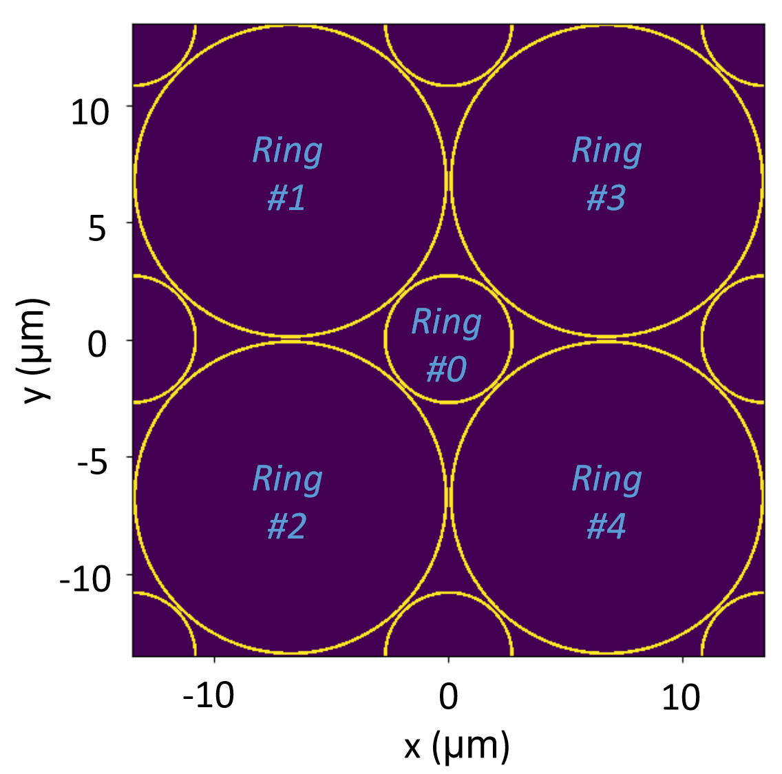
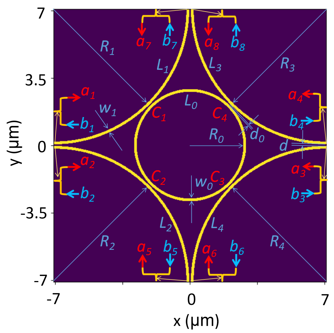
The geometry structure of the 2D interstitial square microring resonators array is shown in Fig. 1 where 4 unit cells are shown. Rings are the larger site-rings on the 2D square lattice and ring is the smaller interstitial ring. The 4 larger site-rings are identical in size and coupled to the middle smaller interstitial-ring. The unit cell of the 2D interstitial square coupled MRRs array is shown in Fig. 2. Also shown are dimensions for the structure: and are the radii and widths of the larger site-ring and smaller interstitial-ring respectively; similarly, are the gap distance between the larger site-rings and the gap distance between the larger site-ring and the smaller interstitial-ring respectively; finally, are the -arc lengths of the larger site-rings and is the -arc length of the smaller interstitial-ring. Couplers between the site-rings (at the left/bottom/right/top locations) are called the site-site couplers and couplers between the site-ring and the interstitial-ring (at the locations) are called the site-interstitial couplers. The coupling coefficients of the site-site coupler and the site-interstitial coupler are defined as and respectively [93]. In particular, the interstitial square coupled MRRs array has the symmetry [72] when and .
III TMM Formulation
For periodic structure, Floquet-Bloch theory applies and states that the field on the periodic lattice repeats itself with a propagation phase proportional to the propagation wave vector. Mathematically, for any angular frequency , a wave vector exists such that,
| (1) |
with the propagation phase defined as,
where is the field vector at each port defined on the edges of the unit cell in Fig. (2); are the lattice periods in and directions respectively; and are integers at two different lattice sites and is the vector difference between them. Note that due to periodicity, is considered to be equivalent. So, it is only necessary to consider in the first Brillouin Zone (BZ). Also, for the rest of this paper, we assume that the periods are the same for both and directions: , following the symmetry [72].
It is well known that the transfer matrix connects the field at adjacent unit cells [97], [74] as follows,
| (2) |
Substituting Eq. (2) into Eq. (1), the following dispersion relation between the angular frequency and the wave vector as follows,
| (3) |
where is the phase propagation matrix depending on the wave vector and the detailed arrangement of the field vector . The dispersion curve is then obtained by solving the eigen-values/eigen-vectors problem of Eq. (3) after setting for the unit cell, which requires that the following secular equation to be satisfied,
| (4) |
with being the input array of arranged in an appropriate sequence according to a specific geometry under study.
In order for the eigen problem of the secular equation in Eq. (4) to have solution, its determinant should be zero,
| (5) |
It is clear that to obtain the dispersion relation according to Eq. (4), the transfer matrix of the unit cell has to be obtained first.
IV Transfer Matrix of the 2D Interstitial Square Array
To obtain the unit-cell transfer matrix for the 2D interstitial square coupled MRRs array, the forward and backward propagating waves at each port of the unit cell have been defined in Fig. 2: are the forward propagating waves and are the backward propagating waves at each port respectively. The incident input waves array is then given as , with the superscript ′ being the transpose operator. Similarly, the output waves array is given by . So the unit-cell transfer matrix is a 8-by-8 matrix that connects the input and output field vectors of the unit cell,
| (6) |
and the transfer matrix can be obtained by connecting all coupling ports with the transfer matrices given in Table I. The transfer matrices with various inputs combination can be derived from the scattering matrix of the coupler, as shown in Appendix A. Then the secular equation for the obtained transfer matrix is obtained according to Eq. (4),
| (7) |
with
The eigen wave vector can be obtained by solving the determinant equation of Eq. (5),
| (8) |
| Scattering Matrix | Transfer Matrix: Input Ports | Transfer Matrix: Input Ports |
|---|---|---|
V Dispersion Relation
The general form of the transfer matrix and the corresponding determinant of the secular equation given in Eq. (4) are very complicated and contains little insight to understand the dispersion relation. Such general case can only be studied through numerical simulation, which is shown later. However, analytical results exist for special cases, which are of particular interest to understand some properties of the dispersion relation. Here the special cases of equivalent arc phases or are studied for: A) identical couplers, i.e., ; and B) regular square coupled MRRs array, i.e., .
V-A Identical Couplers
In this case, analytical formulas are available for some typical arc lengths of the coupled MRRs and their phases defined as : i) -wavelength ring arc or ; ii) -wavelength ring arc or .
V-A1 -wavelength ring arc
In this case, and the determinant of the secular equation is obtained as
| (9) |
with
where and are the propagation phases along and directions respectively.
-
(i)
BZ line : In this case, and the determinant of the secular equation in Eq. (9) reduces to the following,
(10) from which we can obtain the four doubly-degenerated eigen values,
(11) The wave vector can be obtained from Eq. (11) as follows,
(12) and the eigen wave vectors are real because for .
-
(ii)
BZ line :
In this case, Eq. (9) reduces to the following,
(13) Following similar procedure that leads to Eq. (12), the following is obtained,
(14) and thus the eigen wave vectors are also all real.
V-A2 -wavelength ring arc
In this case, and the determinant of the secular equation has the following coefficients,
-
(i)
BZ line : In this case, the determinant of the secular equation is obtained as
(15) from which the four eigen wave vectors can be obtained as follows,
(16) which are imaginary for , which means exponential decay/loss and growth/gain for negative/positive imaginary values respectively. For , the eigen wave vectors are real and given by,
(17) -
(ii)
BZ line :
In this case, the determinant of the secular equation is obtained as follows,
(18) from which the four doubly-degenerated eigen wave vectors can be obtained as follows,
(19) which are all real because .
V-B Regular Square Coupled MRRs Array
When the interstitial rings are decoupled from the site rings, it becomes the regular square coupled MRRs array. The general dispersion can be obtained as follows,
| (20) | |||
V-B1 -wavelength ring arc
When the arc length of the ring is an integer number of quarter wavelength (), and Eq. (20) reduces to the following,
| (21) |
which doesn’t depend on the coupling coefficient and two doubly degenerated solutions are obtained,
| (22) |
and the doubly-degenerated eigen wave vectors are given by,
| (23) |
In particular, the four eigen wave vectors are all degenerated for or ,
| (24) | |||
where and are equivalent due to the periodicity.
V-B2 -wavelength ring arc
When the arc length of the ring is an integer number of 1/8 wavelength (), and Eq. (20) reduces to the following,
| (25) |
from which the two doubly degenerated solutions are obtained as follows,
| (26) |
and the four doubly-degenerated eigen wave vectors given by,
| (27) |
Similarly, the four eigen wave vectors are all degenerated for for or ,
| (28) | |||
VI Band Gaps
The band gap of the dispersion can be obtained by finding the minimum distance of the dispersion curve along the BZ lines . The solutions of for points can be obtained by setting , , respectively in the transfer matrix of the secular equation in Eq. (7).
VI-A Identical Couplers
VI-B Regular Square Coupled MRRs Array
The points of the regular square coupled MRRs array can be obtained in a similar way. It is found that the point and the point are identical, which satisfies the following equation,
| (32) | |||
The point equation is given by,
| (33) | |||
VII Eigen Modes
The eigen values and eigen modes can be obtained by solving the secular equation in Eq. (7). The general forms of the eigen values and eigen modes can only be obtained through numerical simulation. However, for some typical cases of particular interest, analytical formulas can help to understand the behaviors of the 2D interstitial square coupled MRRs array.
VII-A Identical Couplers
When , analytical forms of the eigen values can be obtained for some particular cases.
VII-A1 -wavelength ring arc
In this case, the Bloch eigen modes are doubly degenerated and their eigen values can be obtained. However, the analytical forms of the eigen vectors are very complicated and they are better obtained numerically.
-
(i)
For ,
-
(ii)
For ,
VII-A2 -wavelength ring arc
In this case, the eigen values are given as follows,
-
(i)
For ,
-
(ii)
For ,
| point: Bloch mode #1 | |
|---|---|
| point: Bloch mode #2 | |
| point: Bloch mode #1 | |
| point: Bloch mode #2 | |
| point: Bloch mode #1 | |
| point: Bloch mode #2 | |
| point: Bloch mode #1 | |
| point: Bloch mode #2 |
VII-B Regular Square Coupled MRRs Array
In this case, the eigen values/eigen modes for the points of some typical ring arc lengths can be obtained.
VII-B1 -wavelength ring arc
In this case, and the four eigen modes reduce to two degenerated Bloch modes at the BZ points and . The Bloch modes (both eigen values and eigen vectors) are given in Table II for the incident input waves array and the output waves array are related to the input waves through the Bloch wave condition with the corresponding eigen values according to the secular equation in Eq. (7).
VII-B2 -wavelength ring arc
In this case, and the 4 eigen modes reduce to two degenerated Bloch modes at the BZ point and BZ point . The Bloch modes are also given in Table II.
VIII Simulation Results
Numerical simulation has been performed to obtain the dispersion curves and eigen modes for the 2D interstitial square coupled MRRs array. Here results are shown for some typical cases: 1) identical couplers with a interstitial-ring arc; and 2) regular square coupled MRRs array with a site-ring arc. During simulation a coupling strength of is used.
VIII-A Dispersion Curves
During the simulation, two BZ lines are calculated: i) BZ line; and 2) BZ line, by setting and respectively. When is given, the transfer matrix in Eq. (7) reduces to a matrix with the variable of , which gives four eigenvalues and their corresponding eigen modes for an angular frequency .
VIII-A1 Identical Couplers
In this case, a 2D interstitial square coupled MRRs array with identical couplers () is studied. The arc length of the site-ring is , giving a radius of ; and the arc length of the interstitial-ring is , giving a radius of .
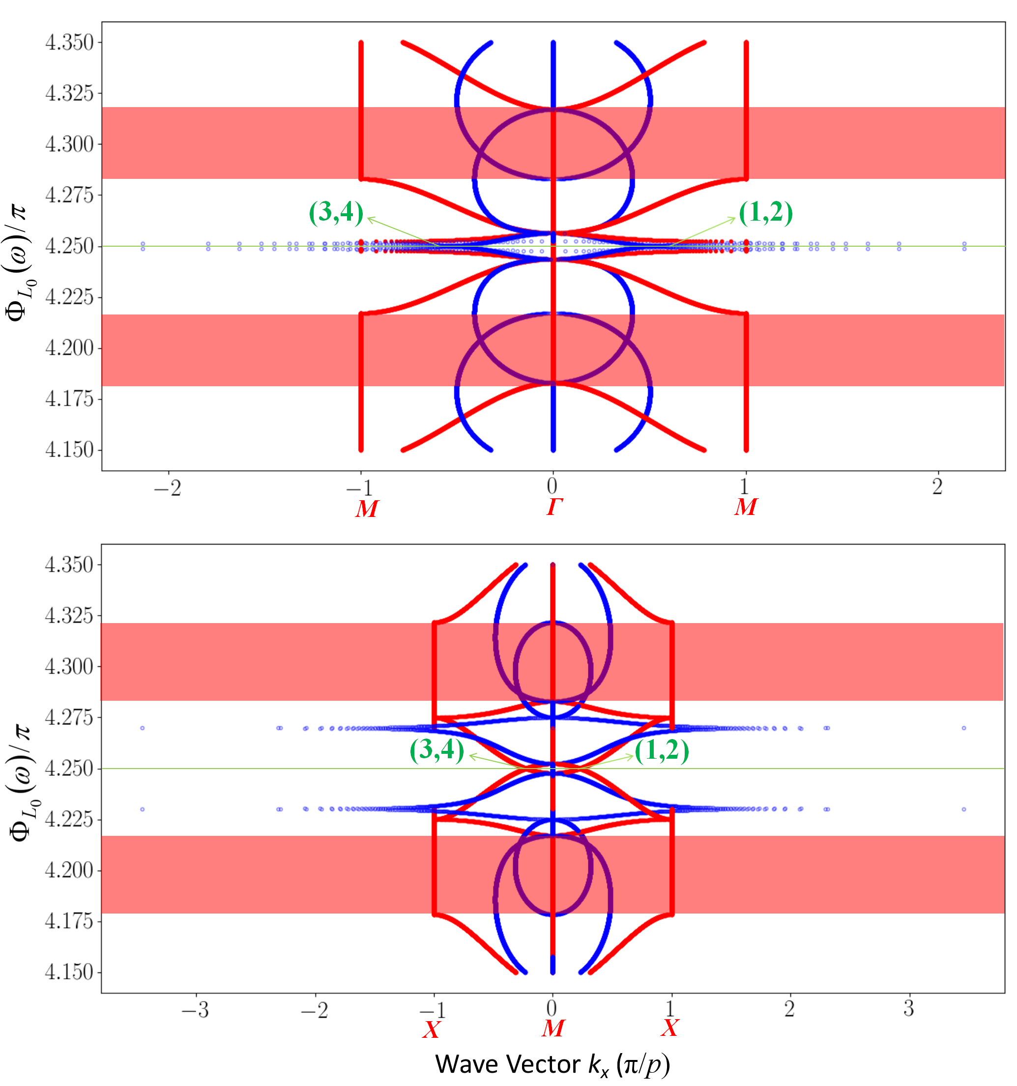
The top plot of Fig. 3 shows the result for the BZ line when : the red/blue lines are the real/imaginary parts of the four eigen values of and the red shaded areas are the bad gaps. Note that the wave vector of the horizontal axis is in the unit of and the vertical axis is the phase of the interstitial-ring’s arc length in the unit of . From Fig. 3, at , the four modes degenerates to two doubly-degenerated eigen modes, as expected in the analytical result given in Eq. (16). The one of the two doubly-degenerated eigen modes is a mode with loss and the other one is a mode with gain because . The eigen wave vectors are obtained as and , verifying the analytical result given in Eq. (16).
VIII-A2 Regular Square Coupled MRRs Array
In this case, a decoupled regular square coupled MRRs array with a coupling strength of is studied. The arc length of the site-ring is .
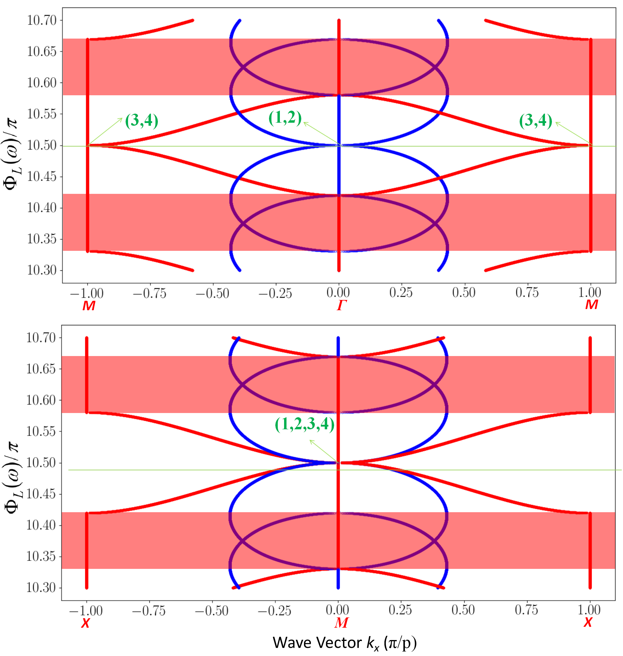
The top plot of Fig. 4 shows the dispersion curve along the BZ line (), from which the eigen wave vectors at are obtained as four degenerated eigen wave vectors: , verifying the analytical result given in Eq. (24).
VIII-B Eigen Modes
After the eigen wave vectors are obtained, the eigen modes’ field distribution can also be calculated through the secular equation given in Eq. (7).
VIII-B1 Identical Couplers
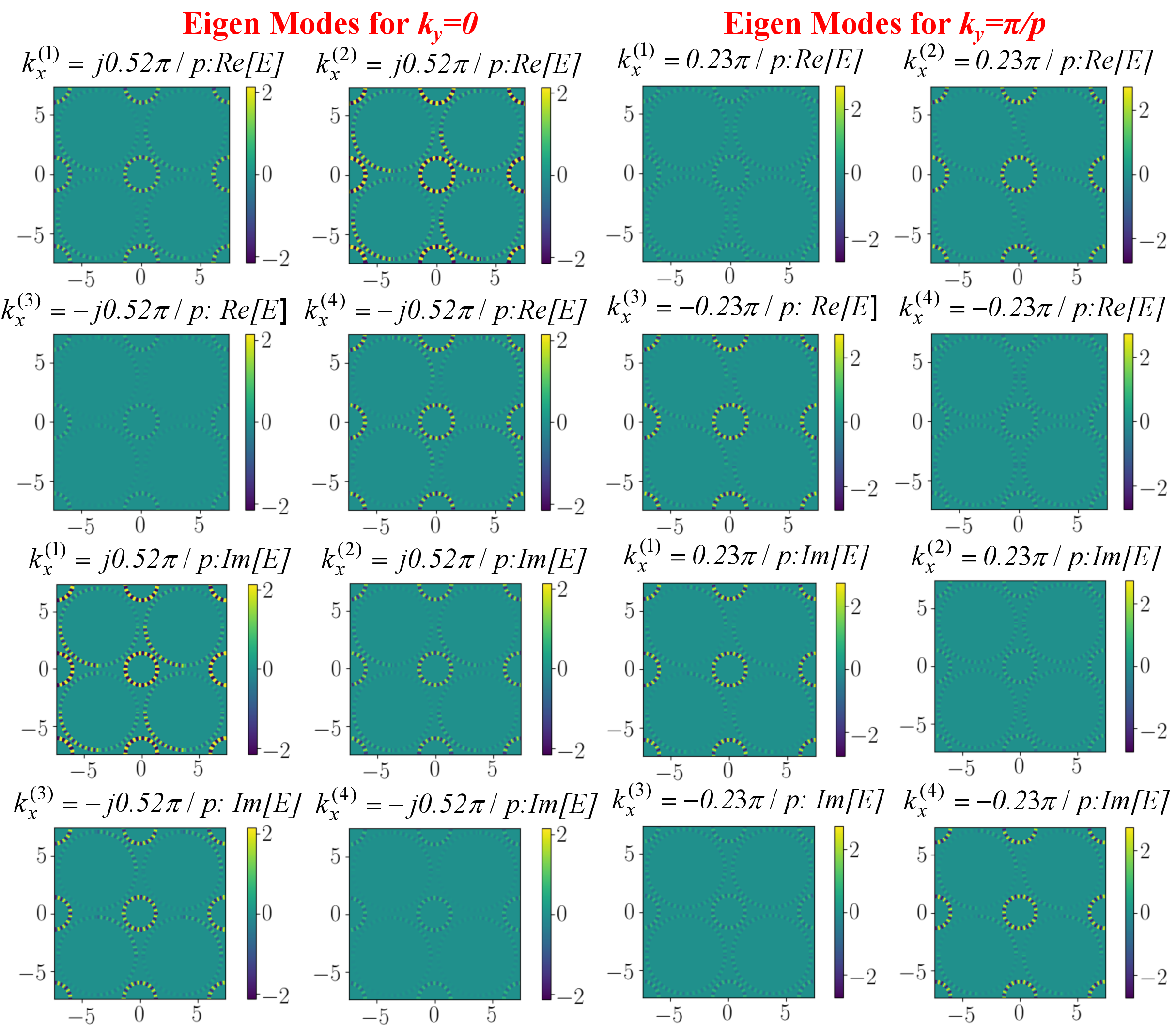
The left plots of Fig. 5 show the four doubly-degenerated eigen modes’ field distribution at , with the corresponding eigen wave vectors (mode with gain) and (mode with loss) shown in the top dispersion plot of Fig. 3. The real/imaginary parts of the eigen modes’ field are shown on the top/bottom plots respectively.
VIII-B2 Regular Square Coupled MRRs Array
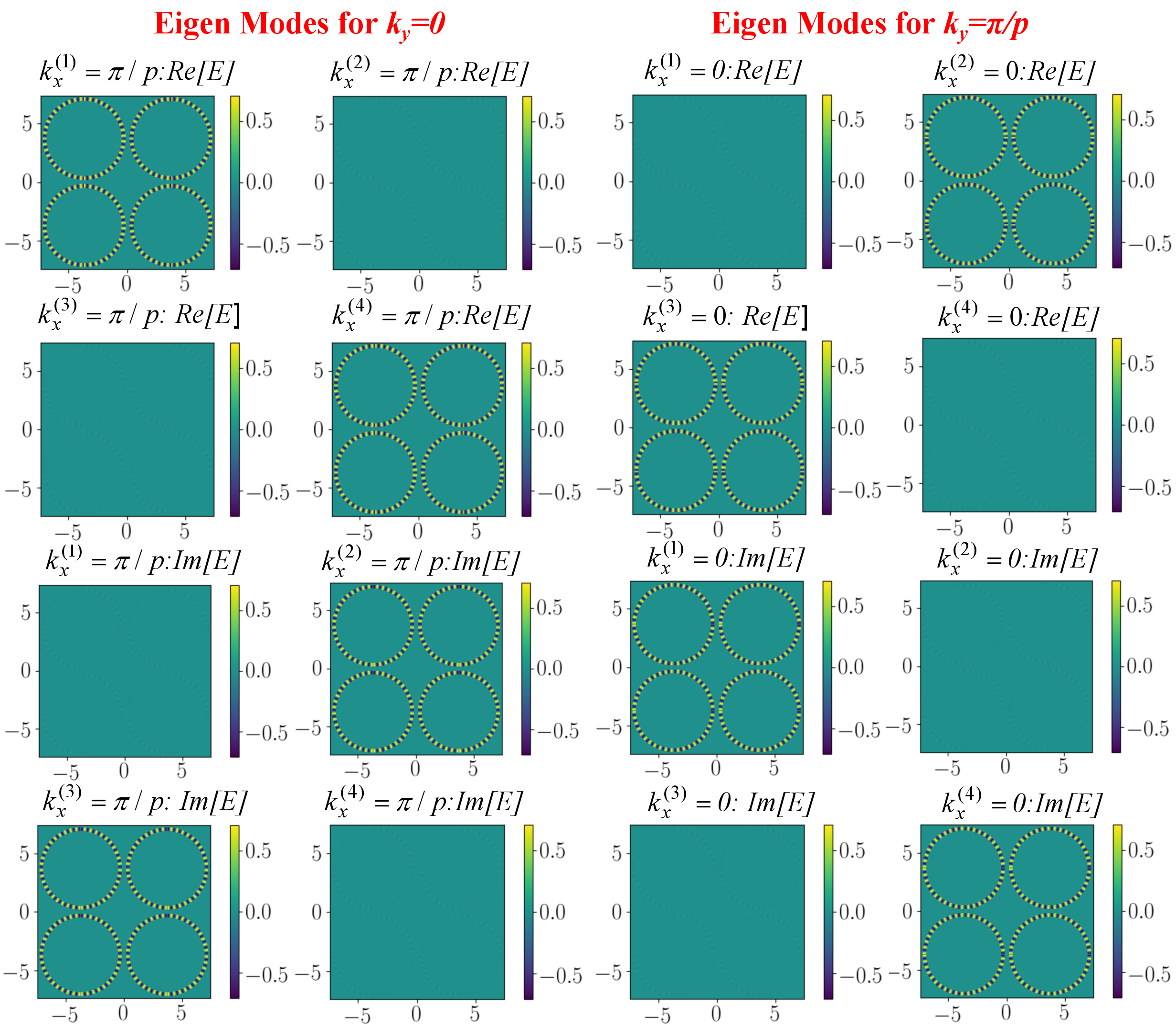
Similarly, Fig. 6 show the eigen modes’ field distribution for the regular square coupled MRRs array (): left) with a four degenerated eigen wave vector of (BZ M point: ), corresponding to the top dispersion plot in Fig. 4; and right) with a four degenerated eigen wave vector of (BZ M point: ), corresponding to the bottom dispersion plot in Fig. 4. Due to the symmetry of the regular square coupled MRRs array [72], the four degenerated eigen modes of can be obtained by rotating those of by .
IX Applications
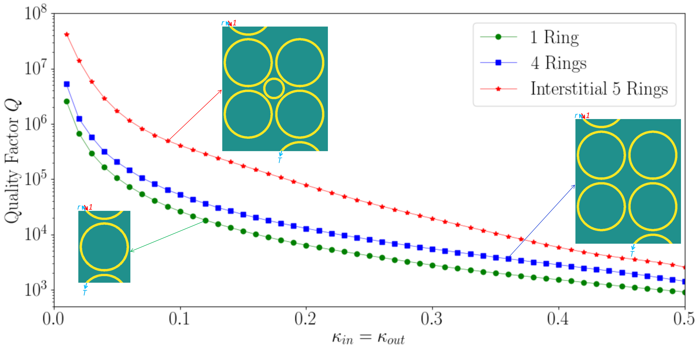
MRRs and arrays have the great potential applications in areas such as integrated filters and resonance based sensing. One important common parameter of MRRs is the quality factor , which is related to the energy dissipation rate of the MRRs. The total quality factor includes both the quality factor due to the intrinsic loss of the MRRs, i.e., and the loaded quality factor due to the coupling to the input/output couplers, i.e., . The quality factor can be studied in two ways [97]: 1) through the group velocity according to the dispersion relation ; and 2) through the Full Width at Half Maximum (FWHM) as . The group velocity method of 1) can provide qualitative insight about the through the dispersion curves such as those in Fig. 3 and Fig. 4; While the FWHM method of 2) is a convenient numerical way to calculate the , with the help of the transfer matrix of the unit cell of the interstitial square coupled MRRs array in Eq. (7) and appropriate terminating boundary conditions. To do this, the reflection and transmission in Fig. 7 can be expanded into the superposition of the eigen modes such as those in Fig. 5 and Fig. 6 with unknown coefficients; then the solution can be obtained by imposing the corresponding boundary conditions. Here the loaded quality factors for three MRRs configurations are calculated with the FWHM method of 2) and compared: i) the 1-ring configuration; ii) the 4-ring configuration; and iii) the interstitial 5-ring configuration. Fig. 7 shows the obtained loaded quality factor vs. the input/output coupling coefficients of the input/output couplers at the top/bottom respectively, for a ring-ring coupling coefficient of . It can be seen that the interstitial 5-ring configuration has a loaded quality factor up to 20 times as high as that of the 1-ring configuration, i.e., = 20 , and up to 8 times as high as that of the 4-ring configuration, i.e., = 8 . This is partly due to that more rings increases the energy storage length. But more importantly, it is due to the dispersion enhancement of the structure geometry configuration: the degeneration of the eigen modes such as those in Fig. 3 allows mixing of the degenerated eigen modes by the incident wave at the input port, greatly increasing the energy stored per unit length of the MRRs and the loaded quality factor is thus dramatically increased. Such high value of loaded quality factor of the interstitial coupled MRRs array makes it a strong candidate to form high-quality filters and resonance based sensing devices. Also, note that the quality factor due to the intrinsic loss can be readily calculated and the total quality factor is given by . What’s more important, when both loss and gain are introduced and balance each other to form the parity-time symmetric sensor, higher quality factor can be obtained [46]. Finally, the quality factor can be further improved by tuning the coupling coefficient of and individually, providing more flexibility to design better integrated photonics components with the interstitial square coupled MRRs array.
X Conclusion
In this paper, the interstitial square coupled MRRs array has been investigated. TMM is used to obtain the dispersion relation under the Floquet-Bloch periodic condition. Analytical formulas of eigen wave vectors, band gaps and eigen modes’ field distribution are derived for the particular cases of the interstitial square coupled MRRs array with identical couplers and the regular square coupled MRRs array. It is found that the eigen modes are doubly degenerated for the 2D interstitial square coupled MRRs array and all four eigen modes are degenerated for the regular 2D square coupled MRRs array, when the arc length is multiple integer of quarter wavelength. Then, the eigen mode field distribution is calculated through the secular equation after the four eigen wave vectors along a BZ line for a given frequency is obtained. Numerical simulation is performed for both a 2D interstitial coupled MRRs array with identical couplers and a regular square coupled MRRs array; the simulation results verify the analytical analysis. At last, it is found that the loaded quality factors of the interstitial 5-ring configuration is up to 20 times and 8 times as high as those of the 1-ring configuration and the regular 4-ring configuration respectively. Such high quality factor indicates that the interstitial square coupled MRRs array has the potential to form high-quality integrated photonics components such as filters and resonance based sensing devices.
Appendix A Scattering and Transfer Matrices of the Coupler
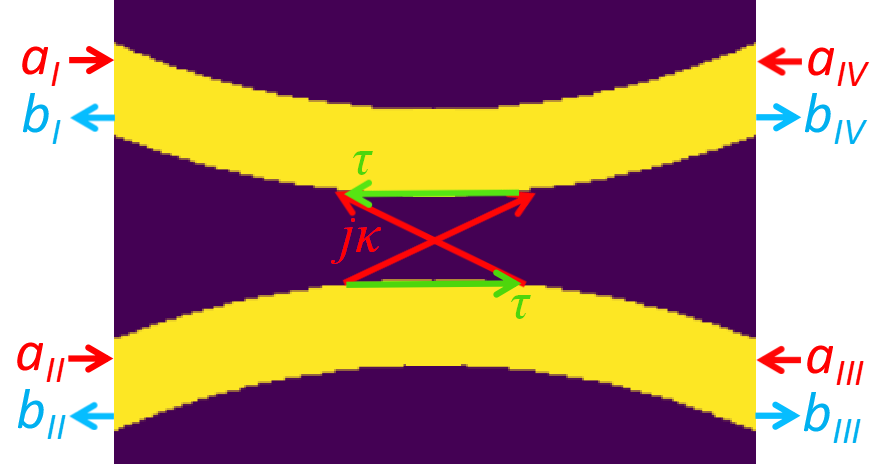
The definition of each port of the coupler is shown in Fig. 8. The incident input waves array and outgoing waves array are given by and respectively.
| (34) |
Depending on the input ports and output ports, the transfer matrix can take different forms. The transfer matrix can be obtained by re-arranging the input/output waves in the scattering matrix given in Eq. (34). The following two transfer matrices are used for the 2D interstitial square coupled MRRs array.
- (i)
- (ii)
Appendix B Transfer Matrix
The transfer matrix in Eq. (7) can be obtained by connecting all the input ports to all the output ports through the two transfer matrices and given in Eq. (35) and Eq. (36) respectively. Here, ports are used as the input ports with the input waves defined as and ports are used as the output ports with the output waves defined as . Then is used for couplers and and is used for all other couplers to connect all input ports to all output ports .
References
- [1] S. Liao and L. Ou, “A Ping-Pong Computational Electromagnetics (CEM) Algorithm for 2D Antennas/Metasurfaces,” 2020 Asia-Pacific Microwave Conference (APMC 2020), Hong Kong SAR, PR China, 8-11 December, 2020. Also available at arXiv.
- [2] Shaolin Liao. Spectral-domain MOM for Planar Meta-materials of Arbitrary Aperture Wave-guide Array. In 2019 IEEE MTT-S International Conference on Numerical Electromagnetic and Multiphysics Modeling and Optimization (NEMO), pages 1-4, May 2019.
- [3] S. Liao and L. Ou, “Iterative Physical Optics (IPO) for Fast and Accurate Simulation of Reflector Antennas,” 2020 Asia-Pacific Microwave Conference (APMC 2020), Hong Kong SAR, PR China, 8-11 December, 2020. arXiv:2007.01861: https://arxiv.org/abs/2007.01861
- [4] S. Liao and L. Ou, “Ultra-sensitive Parity-Time Symmetry based Graphene FET (PTS-GFET) Sensors,” 2020 Asia-Pacific Microwave Conference (APMC 2020), Hong Kong SAR, PR China, 8-11 December, 2020. arXiv:2007.04567: https://arxiv.org/abs/2007.04567
- [5] S. Liao, T. Elmer, S. Bakhtiari, N. Gopalsami, N. Cox, J. Wiencek, A. C. Raptis, “Standoff Through-the-Wall Sensing at Ka-Band Microwave,” Materials Evaluation, American Society of Nondestructive Testing, vol. 70, no. 10, pp. 1136-1145, Oct. 2012. Also available at arXiv:2007.06020, https://arxiv.org/abs/2007.06020.
- [6] Sanchith Padmaraj K. Nirish Patil and S. Liao, “A Compact Dual-band WiFi Energy Harvester,” 2019 Photonics & Electromagnetics Research Symposium - Fall (PIERS - Fall), Xiamen, China, 2019, pp. 1209-1212. DOI: 10.1109/PIERS-Fall48861.2019.9021903
- [7] S. Liao and A. Z. Genack, “Polarization correlation in a quasi-1-D random system,” in Frontiers in Optics 2008/Laser Science XXIV/Plasmonics and Metamaterials/Optical Fabrication and Testing, Rochester, New York, USA, 2008. DOI:10.1364/FIO.2008.FWV3
- [8] Y. He, Y. Li, Z. Zhou, H. Li, Y. Hou, S. Liao and P. Chen, “Wideband Epsilon-Near-Zero Supercoupling Control through Substrate-Integrated Impedance Surface,” Advanced Theory and Simulations, vol. 2, no. 8, p. 1900059, 2019, DOI: 10.1002/adts.201900059.
- [9] S. Liao, Multi-frequency beam-shaping mirror system design for high-power gyrotrons: Theory, algorithms and methods, ProQuest Dissertations And Theses; Thesis (Ph.D.)–The University of Wisconsin - Madison, 2008.; Publication Number: AAI3314260; ISBN: 9780549633167; Source: Dissertation Abstracts International, Volume: 69-05, Section: B, pp. 1-245. https://ui.adsabs.harvard.edu/abs/2008PhDT……..81L/abstract or https://dl.acm.org/doi/book/10.5555/1467404
- [10] L. Ou, S. Liao, Z. Qin, and H. Yin, “Millimeter Wave Wireless Hadamard Image Transmission for MIMO enabled 5G and Beyond,” IEEE Wireless Communications, pp. 1536-1284, 2020. DOI: 10.1109/MWC.001.2000081
- [11] S. Liao, Z. Wang, L. Ou, and Y. Peng, “A Harmonics Interferometric Doppler Sensor With a Neon Lamp Detector,” IEEE Sensors Journal, pp. 1-1, 2020, DOI: 10.1109/JSEN.2020.2970055.
- [12] S. Liao, N. Gopalsami, S. Bakhtiari, T. W. Elmer, E. R. Koehl, and A. C. Raptis, “A novel interferometric sub-THz Doppler radar with a continuously oscillating reference arm,” IEEE Transactions on Terahertz Science and Technology, vol. 4, no. 3, pp. 307-313, Mar. 2014. DOI: 10.1109/TTHZ.2014.2307165
- [13] S. Liao et al., “Passive millimeter-wave dual-polarization imagers,” IEEE Transactions on Instrumentation and Measurement, vol. 61, no. 7, pp. 2042 - 2050, Feb. 2012. DOI: 10.1109/TIM.2012.2183032
- [14] N. Gopalsami, S. Liao, T. Elmer, E. Koehl, A. Heifetz, A. Raptis, L. Spinoulas, and A. Katsaggelos, “Passive millimeter-wave imaging with compressive sensing,” Optical Engineering, vol. 51, no. 9, pp. 091614-1:9, Sep. 2012. DOI: 10.1117/1.OE.51.9.091614
- [15] S. Bakhtiari, T. Elmer, M. Cox, N. Gopalsami, A. Raptis, S. Liao, I. Mikhelson and A. Sahakian, “Compact Millimeter-Wave Sensor for Remote Monitoring of Vital Signs,” IEEE Transactions on Instrumentation and Measurement, vol. 61, no. 3, pp. 830-841, Mar. 2012, DOI: 10.1109/TIM.2011.2171589.
- [16] S. Liao, N. Gopalsami, A. Venugopal, A. Heifetz, and A. C. Raptis, “An efficient iterative algorithm for computation of scattering from dielectric objects,” Optics Express, vol. 19, no. 3, pp. 3304-3315, 2011. DOI: 10.1364/OE.19.003304
- [17] S. Bakhtiari, S. Liao, T. Elmer, N. Gopalsami, and A. C. Raptis, “A real-time heart rate analysis for a remote millimeter wave I-Q sensor,” IEEE Transactions on Biomedical Engineering, vol. 58, no. 6, pp. 1839-45, Mar. 2011. DOI: 10.1109/TBME.2011.2122335
- [18] A. Heifetz, H. T. Chien, S. Liao, N. Gopalsami, and A. C. Raptis, “Millimeter-wave scattering from neutral and charged water droplets,” Journal of Quantitative Spectroscopy and Radiative Transfer, vol. 111, no. 17-18, pp. 2550-2557, 2010. DOI: 10.1016/j.jqsrt.2010.08.001
- [19] S. Liao and R. J. Vernon, “A fast algorithm for computation of electromagnetic wave propagation in half-space,” IEEE Trans. on Antennas and Propagation, vol. 57, no. 7, pp. 2068-2075, Jul. 2009. DOI: 10.1109/TAP.2009.2021890
- [20] S. Liao, “Miter bend mirror design for corrugated waveguides,” Letters of Progress in Electromagnetics Research, vol. 10, pp. 157-162, 2009. DOI: 10.2528/PIERL09062103
- [21] S. Liao and R. J. Vernon, “Sub-THz beam-shaping mirror designs for quasi-optical mode converter in high-power gyrotrons,” Journal of Electromagnetic Waves and Applications, vol. 21, no. 4, pp. 425-439, 2007. DOI: 10.1163/156939307779367332
- [22] S. Liao and R. J. Vernon, “A fast algorithm for wave propagation from a plane or a cylindrical surface,” International Journal of Infrared and Millimeter Wave, vol. 28, no. 6, pp. 479-490, 2007. DOI: 10.1007/s10762-007-9213-0
- [23] S. Liao, “The Taylor Interpolation through FFT Algorithm for Electromagnetic Wave Propagation and Scattering,” arXiv:physics/0610057, Oct. 2006. https://arxiv.org/abs/physics/0610057
- [24] S. Liao and L. Ou, “High-speed Millimeter-wave 5G/6G Image Transmission via Artificial Intelligence,” 2020 Asia-Pacific Microwave Conference (APMC 2020), Hong Kong SAR, PR China, 8-11 December, 2020. arXiv:2007.03153: https://arxiv.org/abs/2007.03153
- [25] I. V. Mikhelson, S. Bakhtiari, T. W. E. II, S. Liao, and A. V. Sahakian, “Remote sensing of heart rate using millimeter-wave interferometry and probabilistic interpolation,” in Proceedings SPIE 8719, Smart Biomedical and Physiological Sensor Technology X, 2013, vol. 87190M. DOI: 10.1117/12.2015282
- [26] S. Liao, N. Gopalsami, S. Bakhtiari, T. Elmer, and A. C. Raptis, “A novel interferometric millimeter wave Doppler radar,” 2013 IEEE International Instrumentation and Measurement Technology Conference (I2MTC), Minneapolis, MN, 2013, pp. 387-391. DOI: 10.1109/I2MTC.2013.6555445
- [27] S. Liao et al., “Millimeter Wave Doppler Sensor for Nondestructive Evaluation of Materials,” 21st Annual Research Symposium & Spring Conference 2012, Dallas, TX USA, 2012. arXiv:2007.00195: https://arxiv.org/abs/2007.00195
- [28] S. Liao, S. Bakhtiari, T. Elmer, A. C. Raptis, I. V. Mikhelson, and A. V. Sahakian, “Millimeter wave I-Q standoff biosensor,” in Proceedings SPIE 8371, Sensing Technologies for Global Health, Military Medicine, Disaster Response, and Environmental Monitoring II; and Biometric Technology for Human Identification IX, 2012, vol. 83711D. DOI: 10.1117/12.924241
- [29] N. Gopalsami, S. Liao, T. Elmer, E. R. Koehl, and A. C. Raptis, “Evaluation of passive millimeter wave system performance in adverse weather,” in Proceedings SPIE 8362, Passive and Active Millimeter Wave Imaging XV, 2012, vol. 83620I. DOI: 10.1117/12.919212
- [30] N. Gopalsami, T. W. Elmer, S. Liao, R. Ahern, A. Heifetz, A. C. Raptis, M. Luessi, D. Babacan and A. K. Katsaggelos, “Compressive sampling in passive millimeter wave imaging,” in Proceedings of SPIE 8022, Passive Millimeter-Wave Imaging Technology XIV, 2011, vol. 80220I. DOI: 10.1117/12.886998
- [31] N. Gopalsami, S. Liao, T. Elmer, A. Heifetz and A. C. Raptis, “Compressive sampling in active and passive millimeter-wave imaging,” 2011 International Conference on Infrared, Millimeter, and Terahertz Waves, Houston, TX, 2011, pp. 1-2. DOI: 10.1109/IRMMW-THz.2011.6105205
- [32] E. Buscarino, S. Liao, M. Perkins, B. Rock, U. Farid and R. Vernon, “High-Power Microwave Transmission and Mode Conversion Program,” Report to USA DOE Office, 2005, DOI: 10.2172/1210042
- [33] S. Liao, “Validity of image theorem under spherical geometry,” Progress in Electromagnetics Research Symposium (PIERS), Marrakesh, Morocco, 2011. arXiv:2007.02000: https://arxiv.org/abs/2007.02000
- [34] S. D. Babacan, M. Luessi, L. Spinoulas, A. K. Katsaggelos, N. Gopalsami, T. Elmer, R. Ahern, S. Liao and A. Raptis, “Compressive passive millimeter-wave imaging,” 2011 18th IEEE International Conference on Image Processing, Brussels, 2011, pp. 2705-2708. DOI: 10.1109/ICIP.2011.6116227
- [35] N. Gopalsami, S. Liao, E. R. Koehl, T. W. Elmer, A. Heifetz, H.-T. Chien and A. C. Raptis, “Passive millimeter wave imaging and spectroscopy system for terrestrial remote sensing,” in Proceedings of SPIE 7670, Passive Millimeter-Wave Imaging Technology XIII, 2010, vol. 767003. DOI:10.1117/12.850123
- [36] R. J. Vernon, S. Liao and J. Neilson, “A high-efficiency four-frequency mode converter design with small output angle variation for a step-tunable gyrotron,” in 2008 33rd International Conference on Infrared, Millimeter and Terahertz Waves, Pasadena, CA, USA, 2008. DOI: 10.1109/ICIMW.2008.4665569
- [37] S. Liao, Vernon RJ and Neilson J., “A four-frequency mode converter with small output angle variation for a step-tunable gyrotron,” Proceedings of the 15th Joint Workshop On Electron Cyclotron Emission and Electron Cyclotron Resonance Heating, EC-15. 477-482, 2009. DOI: 10.1142/9789812814647 0068
- [38] S. Liao, “On the validity of physical optics for narrow-band beam scattering and diffraction from the open cylindrical surface,” Progress in Electromagnetics Research Symposium (PIERS), vol. 3, no. 2, pp. 158-162, 2007. DOI:10.2529/PIERS060906142312
- [39] S. Liao, “Fast computation of electromagnetic wave propagation and scattering for quasi-cylindrical geometry,” Progress in Electromagnetics Research Symposium (PIERS), vol. 3, no. 1, pp. 96-100, 2007. DOI:10.2529/PIERS060906005903
- [40] S. Liao, “Beam-shaping PEC mirror phase corrector design,” Progress in Electromagnetics Research Symposium (PIERS), vol. 3, no. 4, pp. 392-396, 2007. DOI:10.2529/PIERS061005101313
- [41] S. Liao and R. J. Vernon, “The near-field and far-field properties of the cylindrical modal expansions with application in the image theorem,” 2006 Joint 31st International Conference on Infrared Millimeter Waves and 14th International Conference on Teraherz Electronics, Shanghai, 2006, pp. 260-260. DOI: 10.1109/ICIMW.2006.368468
- [42] S. Liao and R. J. Vernon, “The cylindrical Taylor-interpolation FFT algorithm,” 2006 Joint 31st International Conference on Infrared Millimeter Waves and 14th International Conference on Teraherz Electronics, Shanghai, 2006, pp. 259-259. DOI: 10.1109/ICIMW.2006.368467
- [43] S. Liao and R. J. Vernon, “On the image approximation for electromagnetic wave propagation and PEC scattering in cylindrical harmonics,” Progress In Electromagnetics Research, Vol. 66, 65-88, 2006. DOI:10.2528/PIER06083002
- [44] S. Liao and R. J. Vernon, “On fast computation of electromagnetic wave propagation through FFT,” 2006 7th International Symposium on Antennas, Propagation & EM Theory, Guilin, 2006, pp. 1-4. DOI: 10.1109/ISAPE.2006.353495
- [45] S. Liao and R. J. Vernon, “A new fast algorithm for field propagation between arbitrary smooth surfaces,” 2005 Joint 30th International Conference on Infrared and Millimeter Waves and 13th International Conference on Terahertz Electronics, Williamsburg, VA, USA, 2005, pp. 606-607 vol. DOI: 10.1109/ICIMW.2005.1572687
- [46] M. Hajizadegan, M. Sakhdari, S. Liao, and P.-Y. Chen, “High-Sensitivity Wireless Displacement Sensing Enabled by PT-Symmetric Telemetry,” IEEE Transactions on Antennas and Propagation, vol. 67, no. 5, pp. 3445-3449, May 2019, DOI: 10.1109/TAP.2019.2905892.
- [47] L. Zhu, N. Alkhaldi, H. M. Kadry, S. Liao, and P.-Y. Chen, “A Compact Hybrid-Fed Microstrip Antenna for Harmonics-Based Radar and Sensor Systems,” IEEE Antennas and Wireless Propagation Letters, vol. 17, no. 12, pp. 2444-2448, Dec. 2018, DOI: 10.1109/LAWP.2018.2877674.
- [48] S. Liao et al., “Nuclear radiation induced atmospheric air breakdown in a spark gap,” IEEE Transactions on Plasma Science, vol. 40, no. 4, pp. 990-994, Mar. 2012. DOI: 10.1109/TPS.2012.2187343
- [49] S. Liao et al., “Microwave Remote Sensing of Ionized Air,” IEEE Geoscience and Remote Sensing Letters, vol. 8, no. 4, pp. 617-620, Jul. 2011, DOI: 10.1109/LGRS.2010.2098016.
- [50] K. Wang, H. T. Chien, S. Liao, L. P. Yuan, S. H. Sheen, S. Bakhtiari and A. C. Raptis, “Ultrasonic and electromagnetic sensors for downhole reservoir characterization,” in Proceedings of Thirty-Sixth Workshop on Geothermal Reservoir Engineering, Stanford University, Stanford, California, January 31 - February 2, 2011 SGP-TR-191. arXiv:2007.00191: https://arxiv.org/abs/2007.00191
- [51] H. Soekmadji, S. Liao, and R. J. Vernon, “Experiment and simulation on TE10 cut-off reflection phase in gentle rectangular downtapers,” Letters of Progress in Electromagnetics Research, vol. 12, pp. 79-85, 2009. DOI: 10.2528/PIERL09090707
- [52] H. Soekmadji, S. Liao, and R. J. Vernon, “Trapped mode phenomena in a weakly overmoded waveguiding structure of rectangular cross section,” Journal of Electromagnetic Waves and Applications, vol. 22, no. 1, pp. 143-157, 2008. DOI: 10.1163/156939308783122706
- [53] Y. Peng and S. Liao, “Bound States in Continuum and Zero-Index Metamaterials: A Review,” arXiv:2007.01361, Jul. 2020. https://arxiv.org/abs/2007.01361
- [54] S. Liao, “Optimal Feedback-Interferometric Fiber Laser Sensors,” 2019 Photonics & Electromagnetics Research Symposium - Fall (PIERS - Fall), Xiamen, China, 2019, pp. 63-65. DOI: 10.1109/PIERS-Fall48861.2019.9021883
- [55] Y. Peng and S. Liao, “On-chip ZIM-BiC Laser,” in 2019 IEEE MTT-S International Conference on Numerical Electromagnetic and Multiphysics Modeling and Optimization (NEMO), 2019, pp. 1-4. DOI: 10.1109/NEMO.2019.8853827.
- [56] Y. Zeng, Z. Tang, S. Liao and Y. Peng, “On-chip Coupler Using Zero-index Metamaterials,” 2019 Photonics & Electromagnetics Research Symposium - Fall (PIERS - Fall), Xiamen, China, 2019, pp. 1458-1460. DOI: 10.1109/PIERS-Fall48861.2019.9021503
- [57] Y. Peng and S. Liao, “ZIM Laser: Zero-Index-Materials Laser,” IEEE Journal on Multiscale and Multiphysics Computational Techniques, vol. 4, pp. 133-142, 2019, DOI: 10.1109/JMMCT.2019.2905368.
- [58] S. Liao and L. Ou, “High-Q Interstitial Square Coupled Microring Resonators Arrays,” IEEE Journal of Quantum Electronics, 23 April 2020. DOI: 10.1109/JQE.2020.2989809
- [59] S. Liao, T. Wong, and L. Ou, “Optimal feedback-interferometric fifer laser microphones,” Optics Letters, Optical Society of America (OSA), vol. 45, no. 2, pp. 423-426, Jan. 2020, DOI: 10.1364/OL.384225.
- [60] S. Liao and T. Wong, “Optimal Design of Feedback-Interferometric Fiber Laser Sensors,” IEEE Sensors Journal, vol. 19, no. 24, pp. 12016-12023, Dec. 2019, DOI: 10.1109/JSEN.2019.2936222.
- [61] S. Liao, T. Wong, Z. Wang, R. Wang, E. Clutter, and H.-T. Chien, “Miniature fiber laser microphones with graphene diaphragms,” 2018 IEEE Research and Applications of Photonics In Defense Conference (RAPID), Miramar Beach, FL, 2018, pp. 1-4. DOI: 10.1109/RAPID.2018.8508963
- [62] S. Liao and L. Ou, “Quasi Modes and Density of States (DOS) of 1D Photonics Crystal,” available at https://arxiv.org, July 2020.
- [63] E. Clutter B. Matos, Z. Wang, R. Divan, A. Macrander and S. Liao, X-ray Writing of Optical Fiber Gratings with a nm-Mask, The American Vacuum Society (AVS) Prairie Chapter, The University of Chicago, IL USA, 2018. arXiv:2007.00683, https://arxiv.org/abs/2007.00683
- [64] Robinson, Savarimuthu and Nakkeeran, Rangaswamy, “Photonic crystal ring resonator-based add drop filters: a review,” Optical Engineering, Vol. 52, No. 6, pp. 060901, 2013.
- [65] Yu, Zhihua and Han, Tao and Wang, Guangjun and Qi, Guang and Luo, Fengguang and Li, Bin, “8ÿ8 passive noblocking microring resonator crossbar for on-chip WDM-based interconnection network,” Optik - International Journal for Light and Electron Optics, Vol. 124, No. 18, pp. 3734-3738, 2013.
- [66] Dunmeekaew, U. and Pornsuwancharoen, N. and Yupapin, P. P., “New wavelength division multiplexing bands generated by using a Gaussian pulse in a microring resonator system,” Microwave and Optical Technology Letters, Vol. 52, No. 1, pp. 98–101. DOI 10.1002/mop.24880
- [67] Katti, Rohan and Prince, Shanthi, “Photonic Delay Lines Based on Silicon Coupled Resonator Optical Waveguide Structures,” Vol. 10, No. 6, pp. 2793–2800, 2018. DOI: 10.1007/s12633-018-9819-y
- [68] Miri, Mohammad-Ali and Alù, Andrea, “Exceptional points in optics and photonics,” Science, Vol. 363, No. 6422, pp. eaar7709, 2019. DOI: 10.1126/science.aar7709
- [69] Zeng, Xiaoge and Gentry, Cale M. and Popović, Miloš A., “Four-wave mixing in silicon coupled-cavity resonators with port-selective, orthogonal supermode excitation,” Optics Letters, Vol. 40, No. 9, pp. 2120, 2015. DOI: 10.1364/OL.40.002120.
- [70] , “Optical Parametric Generation in a Lithium Niobate Microring with Modal Phase Matching,” Physical Review Applied, Vol. 11, No. 3, pp. 034026, 2019. DOI: 10.1103/PhysRevApplied.11.034026
- [71] , “Nonclassical Optical Bistability and Resonance-Locked Regime of Photon-Pair Sources Using Silicon Microring Resonator,” Physical Review Applied, Vol. 11, No. 3, pp. 034007, 2019. DOI: 10.1103/PhysRevApplied.11.034007
- [72] , “Dirac cone in two- and three-dimensional metamaterials,” Optics Express, Vol. 20, No. 4, pp. 3898–3917, 2012. DOI: 10.1364/OE.20.003898
- [73] Peng, Y. and Liao, S., “ZIM Laser: Zero-Index-Materials Laser,” Vol. 4, pp. 133–142, 2019. DOI: 10.1109/JMMCT.2019.2905368
- [74] Liao, S. and Wong, T., “Optimal Design of Feedback-Interferometric Fiber Laser Sensors,” IEEE Sensors Journal, Vol. 19, No. 24, pp. 1–8, 2019. DOI: 10.1109/JSEN.2019.2936222
- [75] E. Heebner, John and Boyd, Robert W. and Park, Q-Han, “Slow light, induced dispersion, enhanced nonlinearity, and optical solitons in a resonator-array waveguide,” Physical Review E, Vol. 65, No. 3, pp. 036619, 2002. DOI: 10.1103/PhysRevE.65.036619
- [76] , “Designing coupled-resonator optical waveguide delay lines,” JOSA B, Vol. 21, No. 9, pp. 1665–1673, 2004. DOI: 10.1364/JOSAB.21.001665
- [77] Poon, Joyce K. S. and Scheuer, Jacob and Mookherjea, Shayan and Paloczi, George T. and Huang, Yanyi and Yariv, Amnon, “Matrix analysis of microring coupled-resonator optical waveguides,” Optics Express, Vol. 12, No. 1, pp. 90–103, 2004. DOI: 10.1364/OPEX.12.000090
- [78] Poon, J. K. S. and Lin Zhu and DeRose, G. A. and Yariv, A., “Polymer microring coupled-resonator optical waveguides,” Journal of Lightwave Technology, Vol. 24, No. 4, pp. 1843–1849, 2006. DOI: 10.1109/JLT.2006.870971
- [79] Mancinelli, Mattia and Guider, Romain and Masi, Marco and Bettotti, Paolo and Vanacharla, Manga Rao and Fedeli, Jean-Marc and Pavesi, Lorenzo, “Optical characterization of a SCISSOR device,” Optics Express, Vol. 19, No. 14, pp. 13664–13674, 2011. DOI: 10.1364/OE.19.013664
- [80] Malthesh, Shwetha and Krishnaswamy, Narayan, “Improvement in quality factor of double microring resonator for sensing applications,” Journal of Nanophotonics, Vol. 13, No. 2, pp. 026014, 2019. DOI: 10.1117/1.JNP.13.026014
- [81] Heuck, Mikkel and Koefoed, Jacob Gade and Christensen, Jesper Bjerge and Ding, Yunhong and Frandsen, Lars Hagedorn and Rottwitt, Karsten and Oxenløwe, Leif Katsuo, “Unidirectional frequency conversion in microring resonators for on-chip frequency-multiplexed single-photon sources,” New Journal of Physics, Vol. 21, No. 3, 2019. DOI: 10.1088/1367-2630/ab09a7
- [82] Zhang, Mian and Wang, Cheng and Cheng, Rebecca and Shams-Ansari, Amirhassan and Lončar, Marko, “Monolithic ultra-high-Q lithium niobate microring resonator,” Vol. 4, No. 12, pp. 1536–1537, 2017. DOI: 10.1364/OPTICA.4.001536
- [83] Zheng, Yi and Pu, Minhao and Yi, Ailun and Chang, Bingdong and You, Tiangui and Huang, Kai and Kamel, Ayman N. and Henriksen, Martin R. and Jørgensen, Asbjørn A. and Ou, Xin and Ou, Haiyan, “High-quality factor, high-confinement microring resonators in 4H-silicon carbide-on-insulator,” Optics Express, Vol. 27, No. 9, pp. 13053, 2019. DOI: 10.1364/OE.27.013053
- [84] Scott, Ryan E. and Alsing, Paul M. and Smith, A. Matthew and Fanto, Michael L. and Tison, Christopher C. and Schneeloch, James and Hach, Edwin E., “Scalable controlled-not gate for linear optical quantum computing using microring resonators,” Physical Review A, Vol. 100, No. 2, pp. 022322, 2019. DOI: 10.1103/PhysRevA.100.022322
- [85] Wu, Shangquan and Guo, Yingying and Wang, Wanjun and Zhou, Jie and Zhang, Qingchuan, “Label-free biosensing using a microring resonator integrated with poly-(dimethylsiloxane) microfluidic channels,” Review of Scientific Instruments, Vol. 90, No. 3, pp. 035004, 2019. DOI: 10.1063/1.5074134
- [86] Borghi, Massimo and Trenti, Alessandro and Pavesi, Lorenzo, “Four Wave Mixing control in a photonic molecule made by silicon microring resonators,” Scientific Reports, Vol. 9, No. 1, pp. 1–14, 2019. DOI: 10.1038/s41598-018-36694-5
- [87] , “Strong Nonlinear Coupling in a ${\mathrm{Si}}_{3}{\mathrm{N}}_{4}$ Ring Resonator,” Physical Review Letters, Vol. 122, No. 15, pp. 153906, 2019. DOI: 10.1103/PhysRevLett.122.153906
- [88] Alsing, Paul M. and Hach, Edwin E., “Photon-pair generation in a lossy microring resonator. I. Theory,” Physical Review A, Vol. 96, No. 3, pp. 033847, 2017. DOI: 10.1103/PhysRevA.96.033847
- [89] Inna Krasnokutska, and Jean-Luc J. Tambasco and Alberto Peruzzo, “Tunable large free spectral range microring resonators in lithium niobate on insulator | Scientific Reports,” Scientific Reports, Vol. 9, No. 11086, 2019.
- [90] Amiri, Iraj S. and Ariannejad, M. M. and Daud, S. and Yupapin, P., “High sensitive temperature sensor silicon-based microring resonator using the broadband input spectrum,” Results in Physics, Vol. 9, pp. 1578–1584, 2018. DOI: 10.1016/j.rinp.2018.05.004
- [91] Han, Huangpu and Xiang, Bingxi, “Simulation and analysis of electro-optic tunable microring resonators in silicon thin film on lithium niobate,” Scientific Reports, Vol. 9, No 1, pp. 1-7, 2019. DOI: 10.1038/s41598-019-42818-2
- [92] Zhang, Mian and Buscaino, Brandon and Wang, Cheng and Shams-Ansari, Amirhassan and Reimer, Christian and Zhu, Rongrong and Kahn, Joseph M. and Lončar, Marko, “Broadband electro-optic frequency comb generation in a lithium niobate microring resonator,” Nature, Vol. 568, No. 7752, pp. 373–377, 2019. DOI: 10.1038/s41586-019-1008-7
- [93] Kaplan, A., “Modeling of ring resonators with tunable couplers,” IEEE Journal of Selected Topics in Quantum Electronics, Vol. 12, No. 1, pp. 86-95, 2006. DOI: 10.1109/JSTQE.2005.862948
- [94] Zhang, Yuguang and Hu, Xiao and Chen, Daigao and Wang, Lei and Li, Miaofeng and Feng, Peng and Xiao, Xi and Yu, Shaohua, “Design and demonstration of ultra-high-Q silicon microring resonator based on a multi-mode ridge waveguide,” Vol. 43, No. 7, pp. 1586, 2018. DOI: 10.1364/OL.43.001586
- [95] Radjenović, B. and Radmilović-Radjenović, M. and Beličev, P., “Eigenmodes of finite length silicon-on-insulator microring resonator arrays,” Vol. 49, No. 4, pp. 149, 2017. DOI: 10.1007/s11082-017-0984-9
- [96] Barrios, Carlos Angulo, “Integrated microring resonator sensor arrays for labs-on-chips,” Analytical and Bioanalytical Chemistry, Vol. 403, No. 6, pp. 1467–1475, 2012. DOI: 10.1007/s00216-012-5937-3
- [97] Nada, Mohamed Y. and Othman, Mohamed A. K. and Capolino, Filippo, “Theory of coupled resonator optical waveguides exhibiting high-order exceptional points of degeneracy,” Vol. 96, No. 18, pp. 184304, 2017. DOI: 10.1103/PhysRevB.96.184304
- [98] Steglich, Patrick and Hülsemann, Marcel and Dietzel, Birgit and Mai, Andreas, “Optical Biosensors Based on Silicon-On-Insulator Ring Resonators: A Review”, Vol. 24, No. 3, pp. 519, 2019. DOI: 10.3390/molecules24030519
- [99] Tan, Ying and Dai, Daoxin, “Silicon microring resonators,” Vol. 20, No. 5, pp. 054004, 2018. DOI: 10.1088/2040-8986/aaba20
- [100] Bogaerts, W. and De Heyn, P. and Van Vaerenbergh, T. and De Vos, K. and Kumar Selvaraja, S. and Claes, T. and Dumon, P. and Bienstman, P. and Van Thourhout, D. and Baets, R., “Silicon microring resonators,” Vol. 6, No. 1, pp. 47–73, 2012. DOI: 10.1002/lpor.201100017