Unveiling Giant Hidden Rashba Effects in Two-Dimensional Si2Bi2
Abstract
Recently, it has been known that the hidden Rashba (R-2) effect in two-dimensional materials gives rise to a novel physical phenomenon called spin-layer locking (SLL). However, not only has its underlying fundamental mechanism been unclear, but also there are only a few materials exhibiting weak SLL. Here, through the first-principles density functional theory and model Hamiltonian calculation, we reveal that the R-2 SLL can be determined by the competition between the sublayer-sublayer interaction and the spin-orbit coupling (SOC), which is related to the Rashba strength. In addition, the orbital angular momentum distribution is another crucial point to realize the strong R-2 SLL. We propose that a novel 2D material Si2Bi2 possesses an ideal condition for the strong R-2 SLL, whose Rashba strength is evaluated to be 2.16 eVÅ, which is the greatest value ever observed in 2D R-2 materials to the best of our knowledge. Furthermore, we reveal that the interlayer interaction in a bilayer structure ensures R-2 states spatially farther apart, implying a potential application in spintronics.
I Introduction
The spin-orbit coupling (SOC) combined with an asymmetric crystal potential at surfaces or interfaces induces spin-polarized electronic states, called as Rashba (R-1) spin splitting. Rashba (1960); Bychkov and Rashba (1984); Manchon et al. (2015) The Rashba states exhibit unique band dispersion with spin-momentum locking, which can be described by
| (1) |
where , , and represent a Rashba strength coefficient, a Pauli spin matrix vector, and a crystal momentum; and indicates a direction of the local electric field induced by the asymmetric crystal potential. The unique physical properties of the Rashba states have been utilized to realize some crucial concepts in the spintronics, Fabian et al. (2007); Chappert et al. (2007) such as spin field transistor Datta and Das (1990); Koo et al. (2009) and intrinsic spin Hall effects. Sinova et al. (2004)
It has, however, been reported that the Rashba spin splitting is strongly affected by local orbital angular momentum (OAM) in a system with a SOC, Park et al. (2011, 2012); Kim et al. (2012, 2013) which can be described by the orbital Rashba Hamiltonian
| (2) |
where is electric dipole moment produced by the asymmetric charge distribution, Park et al. (2011) and is a proportional coefficient. Since the Rashba effects from these two model Hamiltonians Eqs. (1) and (2) may not be distinguished in band calculations, Eq. (1) may be used to extract the Rashba strength from the Rashba states.
Since the centrosymmetry guarantees the spin-degenerate electronic structures, only non-centrosymmetric system have been considered as candidates for the R-1 based spintronics applications. Recently, however, new insights were suggested that local symmetry breaking may induce “local Rashba” (R-2) spin splitting even in centrosymmetric materials Zhang et al. (2014); Riley et al. (2014). In such systems, intriguingly, degenerate spin states protected by the centrosymmetry are spatially separated into each inversion partner, which can be experimentally detected by spin- and angle-resolved photoemission spectroscopy in both bulk and two-dimensional (2D) materials Riley et al. (2014); Razzoli et al. (2017); Yao et al. (2017); Santos-Cottin et al. (2016); Wu et al. (2017). Among materials exhibiting the R-2 effects, bulk systems are not suitable for utilizing the spatially-separated states because their localized spin states would be canceled out by their adjacent inversion partners. In the van der Waals (vdW) 2D materials, on the other hand, opposite spins in the degenerate states can be split into the top and bottom layers (or atomic sub-layers). Such a spatially-separated spin splitting is called spin-layer locking (SLL). Riley et al. (2014); Yao et al. (2017); Razzoli et al. (2017)
Even though a few experimental observations have shown clear evidences for the existence of the R-2 effects, the following important questions still remain unanswered. 1) Why do some R-2 materials exhibit parabolic band structure rather than the Rashba-like dispersion? 2) How can the R-2 SLL effect be distinguished from unavoidable substrate effects in the experiments? Li and Appelbaum (2018) 3) Why does the degree of spin segregation depend on the band index of an R-2 material? In addition, some of R-2 materials display an energy gap between the upper and lower R-2 bands, which cannot be described by the conventional Rashba (R-1) model Hamiltonian given by Eq. (1). Therefore, a new model Hamiltonian is required to correctly describe the R-2 SLL. Furthermore, to utilize the R-2 Rashba states in the spintronics applications, it is essentially demanded not only to understand the fundamental physics of the R-2 effects but also to search for 2D materials exhibiting strong R-2 SLL.
To answer and resolve these questions and issues, in this paper, we propose a novel vdW 2D material Si2Bi2 with strong R-2 SLL and explore the physical origins combining the first-principles density functional theory and a model Hamiltonian. We found that the strong SOC restricts wavefunction overlap between local inversion partner and enables the OAM to contribute to the band-selected Rashba effects, leading to the giant R-2 SLL. The Rashba strength of Si2Bi2 was calculated to be 2.16 eVÅ, which is the greatest value ever observed in 2D R-2 materials to the best of our knowledge. In addition, we suggest that multilayer configuration may enhance the spatial segregation of spin splitting occurring only at the outermost surfaces, while diminishing almost completely at the inner ones due to the interlayer interactions. Such a stacking process eventually leads to the evolution from the R-2 to R-1 spin splitting.
II Results and discussion
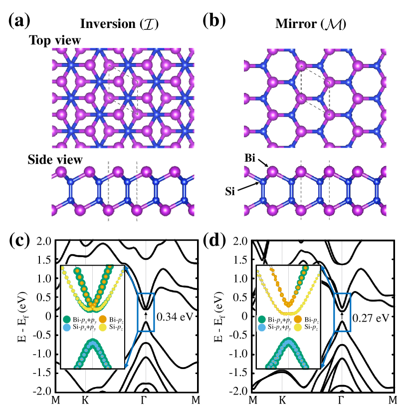
Earlier studies reported that a group IV elements, X (XC, Si, Ge, Sn, or Pb) can combine with a group V elements, Y (YN, P, As, Sb, or Bi) to form a stable layered compound X2Y2. Özdamar et al. (2018); Zhang et al. (2018); Lee and Kwon (2020) Each layered compound can be classified into two groups by the crystal symmetries, one with the nversion symmetry () and the other the irror one (), as shown in Figures 1 (a) and (b). It is noted that their space gruops of these two crystal phases of X2Y2 are essentially the same as those of the 1H and 1T phases of transition metal (M) dichalcogenides (A2), MA2, with the correspondences of X2 and Y to M and A, respectively. Among various group IV-V compounds, we propose that Si2Bi2 becomes an exemplary material exhibiting strong R-2 type Rashba effects. It was found that both and phases of Si2Bi2 are stable with their energy difference of less than 3 meV/atom. Lee and Kwon (2020)
Figures 1 (c) and (d) shows their corresponding electronic band structures calculated using the PBE XC functional, and their orbital-resolved ones in the respective insets, which will be discussed later. Both - and -phases have a band gap of 0.34 and 0.27 eV at the point. 111it is noted that the -phase is an indirect band gap semiconductor with 0.31 eV since the conduction band at that M point is slightly lower that that at the point. The inversion symmetry in the phase guarantees degenerate spin states, whereas the mirror symmetry in the phase lifts the degeneracy. Nevertheless, both phases revealed the Rashba-type splitting near their conduction band minima, but not near the valence band maxima in their band structures. To verify that such a Rashba-type splitting is not a functional-dependent artifact, we also used the HSE06 XC functional, which yields Rashba-like band structures in both phases as shown in Fig. S1 in the Supplementary Information (SI). To get better understanding of these unusual Rashba effects, we first focus our discussion on the phase with higher symmetric features and then on the phase
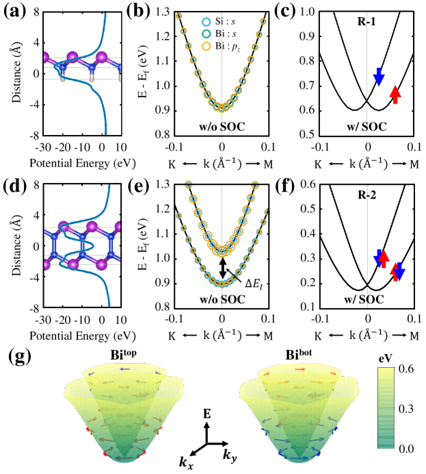
To verify if the Bi-Si system indeed produces the Rashba splitting, as a first step, we constructed an artificial substrucure composed of Bi-Si monolayer with a broken inversion symmetry as shown in Fig. 2 (a). The dangling bond of each Si atom in the 2D SiBi monolayer was saturated by a hydrogen atom. Due to the atomic arrangement of Bi-Si and the difference in their electron affinities, its strong asymmetric local potential shown in Fig. 2 (a) induces an electric field perpendicular to its plane. We calculated its electronic band structure shown in Fig. S4 in the SI. In the absence of SOC, as shown in Fig. 2 (b), the lowest conduction band (CB1) exhibits spin-degenerate parabolic dispersion relation and is mainly formed by the Bi orbital. With SOC turned-on, the orbital related to the in-plane OAM can give a significant contribution to the Rashba interaction due to the out-of-plane local electric field, as described in Eq. (2). Thus, the 2D SiBi monolayer exhibits a typical R-1 spin splitting as shown in the Fig. 2 (c).
In the real -Si2Bi2 material, however, the underlying physics becomes much more complicated because SL-SL interaction also takes part in determining its electronic structure. Similar to Fig. 2 (a), we also computed the local electrostatic potential of -Si2Bi2 displayed in Fig. 2 (d). Due to the inversion symmetry, there is no net dipole moment. However, the potential profile clearly indicates that there are local dipole moments on the top and bottom SLs, which are oppositely oriented to each other. Were it not for both the SL-SL interaction and SOC, -Si2Bi2 should have had the four-fold degenerate conduction bands composed mainly of the orbitals with spin-up and -down of the top and bottom Bi SLs. Now only turning on SOC, the opposite local electric fields, each on each SL, should have induced the spatially-separated R-2 spin splitting, but the inversion symmetry still guarantees the spin-degeneracy, which are schematically summarized in Fig. S5 in SI.
There is, however, an inevitable interaction between the top and bottom SLs, which lifts their four-fold degeneracy via the wavefunction overlap even without SOC, as shown in Fig. 2 (e). The splitting energy due to such interaction was calculated to be 0.13 eV at the point. One could expect that SOC would split these bands further into two sets of Rashba bands, which is, however, contradictory to degeneracy guaranteed by the inversion symmetry. It was instead surprisingly found that turning on SOC converted two separated doubly-degenerate parabolic bands (Fig. 2 (e)) to almost perfect and doubly-degenerate Rashba bands, as shown in Fig. 2 (f), essentially the same as those expected in the case without the SL-SL interaction as described above and in Fig. S5 in SI. To confirm that such bands are the hidden Rashba bands, we explored the doubly-degenerate Rashba bands (Fig. 2 (f)) by computing the spatially-resolved spin textures 222For a given , the spin polarization is the expectation value of the spin operator, that is, , where is the Pauli spin matrix vector. Its projection on each atom , , was obtained by expanding in terms of the spherical harmonics with the orbital angular momentum of the atom, or . on the top (Bitop) and bottom (Bibot) Bi atom SLs shown in Fig. 2 (g). The spin map on each layer exhibits the opposite spin chiralities on the inner and outer Rashba bands, as usually observed in noncentrosymmetric systems. Even more intriguingly, these spin chiralities are spatially coupled to the layers. The spins of Bitop on the inner band rotate in one way (e.g., counterclockwise, blue arrows in the left image), whereas those of Bibot do in the other way (clockwise, red arrows on the right image). On the outer band, their corresponding spins rotate the other way around. (red arrows on the left and blue arrows on the right images) This observation clearly reveals the strong R-2 SLL phenomenon. Furthermore, it is worthwhile to note the relation between the local symmetry breaking and the orbital polarization described in Eq. (2). We investigated the OAM distributions Ryoo and Park (2017) of both the 2D SiBi monolayer and -Si2Bi2 as described in Sect. IV, and found that the -Si2Bi2 exhibits the “hidden” orbital polarization as well as the R-2 SLL induced by the local symmetry breaking. For detailed description, see Note S1 with Figs. S2 and S3 in SI.
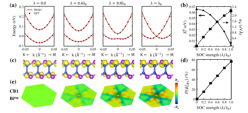
In view of previous results observed in other 2D R-2 materials, such as PtSe2 Yao et al. (2017) or bilayer WSe2 Riley et al. (2014), which have revealed the SLL phenomena, but still with parabolic bands similar to those shown in Fig. 2 (e), our hidden Rashba bands shown in Fig. 2 (f) are exceptionally unusual since they look like the Rashba-like bands shown in Fig. 2 (c). To answer what causes such distinction, we examined the pathway from the parabolic bands (Fig. 2 (e)) to the Rashba-like ones (Fig. 2 (f)) while manipulating the SOC strength , where is the real SOC strength of our -Bi2Si2 system. As increases, two split bands tend to form a Rashba-like bands through continuous change as shown in Fig. 3 (a). This result indicates that the competition between the SL-SL interaction () and the Rashba strength () determines the shape of electronic bands.
To understand such competition quantitatively, we devised a simplest model Hamiltonian represented by four minimal basis vectors that describes the SL-SL interaction and Rashba splitting. For more detailed description of our model Hamiltonian, see Note S2. in SI. From the model Hamiltonian, we obtained two doubly-degenerate bands
| (3) |
guaranteed by inversion symmetry. Here is the effective mass, and the SL-SL interaction coefficients. To discover how to compete the SL-SL interaction with Rashba spin splitting, the DFT bands (black dots) were fitted to the model bands (red lines) given in Eq. (3) resulting in almost perfect agreement as shown Fig. 3 (a). The fitted parameters and as a function of are shown in Fig. 3 (b). As expected, SOC weakens the SL-SL interaction, but strengthens , which was calculated to be 2.16 eVÅ at . This value is much larger than those observed in metal surfaces, for example Au(111) (0.33 eVÅ), LaShell et al. (1996) Bi(111) (0.55 eVÅ), Koroteev et al. (2004) as well as other materials exhibiting the R-2 SOC such as BaNiS2 (0.24 eVÅ), Yuan et al. (2019) and is also comparable with conventional giant Rashba system, such as hybrid perovskites (1.6 eVÅ), Zhai et al. (2017) BiSb monolayer (2.3 eVÅ), Singh and Romero (2017) or BiTeI (3.8 eVÅ), Ishizaka et al. (2011). Therefore, we may classify our system into the first “giant hidden” Rashba material.
This result was further confirmed by , obtained from the spin-resolved wavefunction yielded near the point. As shown in Fig. 3 (c), it evolves from an even distribution on both SLs at toward a complete spatial segregation at , which is quantified by defined by Eq. (5), shown in Fig. 3 (d). For every value, we also reckoned the spatially-resolved spin map on the Bitop SL to verify the degree of the SLL, which shown in Fig. 3 (e). We emphasize that no sharp phase transition was observed and thus even for , the system exhibits the SLL while maintaining two parabolic bands due to appreciable SL-SL interaction. When becomes eventually, all three features clearly reveal complete Rashba-like bands, wavefunction segregation and SLL implying that our system, 2D -Si2Bi2 possesses vastly strong SOC minimizing the SL-SL interaction. We further notice that when becomes larger than , energy gap between CB1 and CB2 reopens, while wavefunctions are still strongly segregated and R-2 SLL is also vivid, as shown in Fig. S6 in SI.
On the other hand, we noticed that there is no Rashba spin splitting at the highest valence band (VB1) unlike at CB1, perusing the band structures shown in Fig. 1 (c). As shown in the inset of Fig. 1 (c) and Fig. S7 (a), there is nearly no orbital contribution at VB1, resulting in no OAM distribution to produce Rashba spin splitting even with strong SOC, which is clear from Eq. (2). This non Rashba feature observed in the VB1 was further confirmed by the spin texture and the wavefunction segregation computed on the VB1 shown in Fig. S7 (b) and (c) in SI. Therefore, to utilize an R-2 material in the spintronics application, its hidden Rashba SLL should be induced by the bands near the Fermi level, which possess the OAM perpendicular to the local electric field.
At this time, it is worth mentioning that the spin splitting was also observed in -Si2Bi2 with the broken inversion symmetry, which additionally lifts the degeneracy protected in the -counterpart and guarantees the Dresselhaus spin splitting. Dresselhaus (1955) Intriguingly, we also observed a strong SLL in a few lowest conduction bands near the point, as shown in Fig. S8 in SI. Such strong SLL is also attributed to the OAM similar in its inversion counterpart. Here, we again emphasize that the OAM is an important factor to determine the SLL.
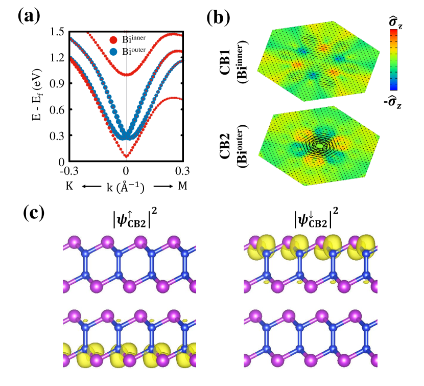
Since 2D materials usually form multilayers rather than monolayers, it is also of importance to understand the effect of the interlayer- or vdW interaction on the SLL phenomenon. To do this, we constructed a bilayer of -Si2Bi2 with “AA” stacking which is still maintains the inversion symmetry, and investigated its electronic properties. Figure 4 (a) shows its four lowest conduction bands (CB1 through CB4 in ascending order in energy) represented by the projections on the inner Bi (Biinner) SLs in red circles and on their outer (Biouter) counterparts in blue circles. The widely-split two red bands (CB1 and CB4) are contributed mostly by the Biinner SLs, whereas the Rashba-like blue bands (CB2 and CB3) mostly by the Biouter ones. Were it not for the vdW interaction, two identical monolayers should have shown exactly the same band structures as shown in Fig. 2 (f) with every band four-fold degenerated. One can, however, easily expect that the Biinner SLs are directly affected by the vdW interaction, whereas the Biouter SLs are intact. Thus it can be explained that the vdW interaction caused the band repulsion between the CB1 and CB4, while the CB2 and CB3 localized at two opposite Biouter SLs preserve the SLL induced in each isolated monolayer.
Our explanation becomes even clearer from the spatially-resolved spin textures and spinor wavefunctions. Spin texture of the Biouter SLs evaluated on the CB2 does show much stronger spin chirality implying stronger SLL than that of the Biinner SLs on the CB1, where R-2 Rashba effects are suppressed, as shown in Fig. 4 (b). To verify if the SLL in the bilayer is indeed from the CB2 and CB3, we represented the spinor wavefunctions squared, in real space. In Fig. 4 (c), those for and calculated on the CB2 clearly display spatially-segregated spin states demonstrating the strong SLL. It is worthy of mentioning that each band is still doubly degenerate since the bilayer configuration also possesses the inversion symmetry. In other word, it is the interlayer interaction that removes the R-2 effect at the inner surfaces, but the Rashba states survive only at the outer surfaces of the bilayer. This spatial segregation would be utilized in some spintronics applications since one could control the spin behaviors only on the top surface without being influenced by those on the bottom one. We also noticed that when the layered R-2 materials become a bulk structure, Rashba spin splittings inside bulk region may be removed as seen in the bilayer, and only the surface Rashba states survive, implying that the R-2 SLL automatically changes to the R-1 spin splitting. It is, therefore, the local symmetry breaking that is the physical origin causing not only the R-2 SLL, but also R-1 effects.
III Conclusion
Using first-principles density functional theory, we predicted a new 2D material, which is layered Si2Bi2 exhibiting the giant R-2 SLL. To understand an underlying physical origin of R-2 SLL, we performed first-principles calculations as well as solved a devised model Hamiltonian to describe the R-2 SLL. Through this model calculation, we found that there is a competition between the SOC and SL-SL interaction to reveal the R-2 SLL. As the former, as it increases, weakens the latter and strengthens leading to the giant hidden Rashba spin splitting. Furthermore we found that the R-2 SLL is also closely related to the OAM distribution. The Rashba strength in Si2Bi2 was calculated to be 2.16 eVÅ, which is the greatest value ever observed in R-2 materials to the best of our knowledge. We also revealed from a bilayer case that the R-2 SLL can be removed at the inner surfaces due to the interlayer interaction, but remained spatially farther apart at the outer surfaces. This eventually leads to a conclusion that the R-1 effect is also originated from the same local symmetry breaking causing the R-2 SLL. Our findings may not only uncover the fundamental physics of R-2 SLL, but also provide a guidance for searching novel R-2 materials.
IV Methods
To understand the underlying physics of the R-2 SLL in 2D Si2Bi2, we performed first-principles calculations based on density functional theory Kohn and Sham (1965) as implemented in Vienna ab initio simulation package (VASP) Kresse and Furthmüller (1996). The electronic wavefunctions were expanded by plane wave basis with kinetic energy cutoff of 500 eV. We employed the projector-augmented wave pseudopotentials Blöchl (1994); Kresse and Joubert (1999) to describe the valence electrons, and treated exchange-correlation (XC) functional within the generalized gradient approximation of Perdew-Burke-Ernzerhof (PBE) Perdew et al. (1996) with noncollinear spin polarization. Steiner et al. (2016) To rule out any functional-related artifacts, we verified our PBE-based results using hybrid functional (HSE06). Krukau et al. (2006) For bilayer calculations, in which interlayer interaction cannot be neglected, Grimme-D2 Van der Waals correction Grimme (2006) was added. To mimic 2D layered structure in periodic cells, we included a sufficiently large vacuum region in-between neighboring cells along the out-of-plane direction. The Brillouin zone (BZ) of each structure was sampled using a -point mesh according to the Monkhost-Pack scheme. Monkhorst and Pack (1976)
To describe and visualize the R-2 SLL, we included spin-orbit interaction in the all calculation. The SOC is described by an additional Hamiltonian
| (4) |
where and indicate spin-up and down components of the spinor wave function; and are Pauli spin matrices and angular momentum operator; is the spherical part of the effective all electron potential within the PAW sphere; and
as explained in Refs. [Steiner et al., 2016] and [Lenthe et al., 1993]. To explore the effect of the SOC strength, we introduced an artificial parameter which scales Eq. (4) as
When , it becomes the full SOC Hamiltonian given in Eq. (4).
The momentum-resolved spinor wavefunctions were evaluated by projecting the two-component spinor
into spherical harmonics centered at ion index with angular momentum quantum numbers . Here and are band index and crystal momentum, and the arrows and represent spin up and down. Such projected components were further manipulated to understand the contribution of each orbital angular momentum to the band structures and to generate the atom-resolved spin texture map.
To verify the SLL in our system, we quantify the spatial spin separation by introducing the degree of wavefucntion segregation (DWS) defined as Yuan et al. (2019),
| (5) |
with
| (6) |
where and , is band index, and indicates the real space sector for the upper Bi-Si () or lower Si-Bi () SL. , for example, represents the wavefunction localized on the upper SL sector .
Acknowledgements.
We gratefully acknowledge financial support from the Korean government through the National Research Foundation (NRF) of Korea (No. 2019R1A2C1005417). Some portion of our computational work was done using the resources of the KISTI Supercomputing Center (KSC-2018-CHA-0052 and KSC-2020-CRE-0011).References
- Rashba (1960) E. I. Rashba, “Properties of semiconductors with an extremum loop. 1. cyclotron and combinational resonance in a magnetic field perpendicular to the plane of the loop,” Sov. Phys. Solid State 2, 1109–1122 (1960).
- Bychkov and Rashba (1984) Y. A. Bychkov and E. I. Rashba, “Properties of a 2d electron gas with lifted spectral degeneracy,” JETP Lett. 39, 78 (1984).
- Manchon et al. (2015) A. Manchon, H. C. Koo, J. Nitta, S. M. Frolov, and R. A. Duine, “New perspectives for rashba spin-orbit coupling,” Nat. Mater. 14, 871–882 (2015).
- Fabian et al. (2007) J. Fabian, A. Matos-Abiague, C. Ertler, P. Stano, and I. Zutic, “Semiconductor spintronics,” Phys. Rev. 57, 565–907 (2007).
- Chappert et al. (2007) C. Chappert, A. Fert, and F. N. Van Dau, “The emergence of spin electronics in data storage,” Nat. Mater. 6, 813–823 (2007).
- Datta and Das (1990) S. Datta and B. Das, “Electronic analog of the electro-optic modulator,” Appl. Phys. Lett. 56, 665 (1990).
- Koo et al. (2009) Hyun Cheol Koo, Jae Hyun Kwon, Jonghwa Eom, Joonyeon Chang, Suk Hee Han, and Mark Johnson, “Control of spin precession in a spin-injected field effect transistor,” Science 325, 1515–1518 (2009).
- Sinova et al. (2004) Jairo Sinova, Dimitrie Culcer, Q. Niu, N. A. Sinitsyn, T. Jungwirth, and A. H. MacDonald, “Universal intrinsic spin hall effect,” Phys. Rev. Lett. 92, 126603 (2004).
- Park et al. (2011) Seung Ryong Park, Choong H. Kim, Jaejun Yu, Jung Hoon Han, and Changyoung Kim, “Orbital-angular-momentum based origin of rashba-type surface band splitting,” Phys. Rev. Lett. 107, 156803 (2011).
- Park et al. (2012) Jin-Hong Park, Choong H. Kim, Jun-Won Rhim, and Jung Hoon Han, “Orbital rashba effect and its detection by circular dichroism angle-resolved photoemission spectroscopy,” Phys. Rev. B 85, 195401 (2012).
- Kim et al. (2012) Beomyoung Kim, Choong H. Kim, Panjin Kim, Wonsig Jung, Yeongkwan Kim, Yoonyoung Koh, Masashi Arita, Kenya Shimada, Hirofumi Namatame, Masaki Taniguchi, Jaejun Yu, and Changyoung Kim, “Spin and orbital angular momentum structure of cu(111) and au(111) surface states,” Phys. Rev. B 85, 195402 (2012).
- Kim et al. (2013) Beomyoung Kim, Panjin Kim, Wonsig Jung, Yeongkwan Kim, Yoonyoung Koh, Wonshik Kyung, Joonbum Park, Masaharu Matsunami, Shin-ichi Kimura, Jun Sung Kim, Jung Hoon Han, and Changyoung Kim, “Microscopic mechanism for asymmetric charge distribution in rashba-type surface states and the origin of the energy splitting scale,” Phys. Rev. B 88, 205408 (2013).
- Zhang et al. (2014) Xiuwen Zhang, Qihang Liu, Jun-Wei Luo, Arthur J. Freeman, and Alex Zunger, “Hidden spin polarization in inversion-symmetric bulk crystals,” Nat. Phys. 10, 387–393 (2014).
- Riley et al. (2014) J. M. Riley, F. Mazzola, M. Dendzik, M. Michiardi, T. Takayama, L. Bawden, C. Granerød, M. Leandersson, T. Balasubramanian, M. Hoesch, T. K. Kim, H. Takagi, W. Meevasana, Ph. Hofmann, M. S. Bahramy, J. W. Wells, and P. D. C. King, “Direct observation of spin-polarized bulk bands in an inversion-symmetric semiconductor,” Nat. Phys. 10, 835–839 (2014).
- Razzoli et al. (2017) E. Razzoli, T. Jaouen, M.-L. Mottas, B. Hildebrand, G. Monney, A. Pisoni, S. Muff, M. Fanciulli, N. C. Plumb, V. A. Rogalev, V. N. Strocov, J. Mesot, M. Shi, J. H. Dil, H. Beck, and P. Aebi, “Selective probing of hidden spin-polarized states in inversion-symmetric bulk ,” Phys. Rev. Lett. 118, 086402 (2017).
- Yao et al. (2017) Wei Yao, Eryin Wang, Huaqing Huang, Ke Deng, Mingzhe Yan, Kenan Zhang, Koji Miyamoto, Taichi Okuda, Linfei Li, Yeliang Wang, Hongjun Gao, Chaoxing Liu, Wenhui Duan, and Shuyun Zhou, “Direct observation of spin-layer locking by local Rashba effect in monolayer semiconducting PtSe2 film,” Nat. Commun. 8, 14216 (2017).
- Santos-Cottin et al. (2016) David Santos-Cottin, Michele Casula, Gabriel Lantz, Yannick Klein, Luca Petaccia, Patrick Le Fèvre, François Bertran, Evangelos Papalazarou, Marino Marsi, and Andrea Gauzzi, “Rashba coupling amplification by a staggered crystal field,” Nat. Commun. 7, 11258 (2016).
- Wu et al. (2017) Shi-Long Wu, Kazuki Sumida, Koji Miyamoto, Kazuaki Taguchi, Tomoki Yoshikawa, Akio Kimura, Yoshifumi Ueda, Masashi Arita, Masanori Nagao, Satoshi Watauchi, Isao Tanaka, and Taichi Okuda, “Direct evidence of hidden local spin polarization in a centrosymmetric superconductor LaO0.55F0.45BiS2,” Nat. Commun. 8, 1919 (2017).
- Li and Appelbaum (2018) Pengke Li and Ian Appelbaum, “Illuminating ”spin-polarized” bloch wave-function projection from degenerate bands in decomposable centrosymmetric lattices,” Phys. Rev. B 97, 125434 (2018).
- Özdamar et al. (2018) Burak Özdamar, Gözde Özbal, M. Ne şet Ç ınar, Koray Sevim, Gizem Kurt, Birnur Kaya, and Hâldun Sevinçli, “Structural, vibrational, and electronic properties of single-layer hexagonal crystals of group iv and v elements,” Phys. Rev. B 98, 045431 (2018).
- Zhang et al. (2018) Wei Zhang, Jiuren Yin, Yanhuai Ding, Yong Jiang, and Ping Zhang, “Strain-engineering tunable electron mobility of monolayer IV-V group compounds,” Nanoscale 10, 16750–16758 (2018).
- Lee and Kwon (2020) Seungjun Lee and Young-Kyun Kwon, “Versatile physical properties of a novel two-dimensional materials composed of group iv-v elements,” arXiv:2007.05137 [cond-mat.mtrl-sci] (2020).
- Note (1) It is noted that the -phase is an indirect band gap semiconductor with 0.31 eV since the conduction band at that M point is slightly lower that that at the point.
- Note (2) For a given , the spin polarization is the expectation value of the spin operator, that is, , where is the Pauli spin matrix vector. Its projection on each atom , , was obtained by expanding in terms of the spherical harmonics with the orbital angular momentum of the atom, or .
- Ryoo and Park (2017) J. Ryoo and C. Park, “Hidden orbital polarization in diamond, silicon, germanium, gallium arsenide and layered materials,” NPG Asia Mater. 9, e382 (2017).
- LaShell et al. (1996) S. LaShell, B. A. McDougall, and E. Jensen, “Spin splitting of an au(111) surface state band observed with angle resolved photoelectron spectroscopy,” Phys. Rev. Lett. 77, 3419–3422 (1996).
- Koroteev et al. (2004) Yu. M. Koroteev, G. Bihlmayer, J. E. Gayone, E. V. Chulkov, S. Blügel, P. M. Echenique, and Ph. Hofmann, “Strong spin-orbit splitting on bi surfaces,” Phys. Rev. Lett. 93, 046403 (2004).
- Yuan et al. (2019) Linding Yuan, Qihang Liu, Xiuwen Zhang, Jun Wei Luo, Shu Shen Li, and Alex Zunger, “Uncovering and tailoring hidden Rashba spin-orbit splitting in centrosymmetric crystals,” Nat. Commun. 10, 906 (2019).
- Zhai et al. (2017) Yaxin Zhai, Sangita Baniya, Chuang Zhang, Junwen Li, Paul Haney, Chuan-Xiang Sheng, Eitan Ehrenfreund, and Zeev Valy Vardeny, “Giant rashba splitting in 2d organic-inorganic halide perovskites measured by transient spectroscopies,” Sci. Adv. 3, e1700704 (2017).
- Singh and Romero (2017) Sobhit Singh and Aldo H. Romero, “Giant tunable rashba spin splitting in a two-dimensional bisb monolayer and in bisb/aln heterostructures,” Phys. Rev. B 95, 165444 (2017).
- Ishizaka et al. (2011) K. Ishizaka, M. S. Bahramy, H. Murakawa, M. Sakano, T. Shimojima, T. Sonobe, K. Koizumi, S. Shin, H. Miyahara, A. Kimura, K. Miyamoto, T. Okuda, H. Namatame, M. Taniguchi, R. Arita, N. Nagaosa, K. Kobayashi, Y. Murakami, R. Kumai, Y. Kaneko, Y. Onose, and Y. Tokura, “Giant Rashba-type spin splitting in bulk BiTeI,” Nat. Mater. 10, 521–526 (2011).
- Dresselhaus (1955) G. Dresselhaus, “Spin-orbit coupling effects in zinc blende structures,” Phys. Rev. 100, 580–586 (1955).
- Kohn and Sham (1965) W Kohn and L J Sham, “Self-Consistent Equations Including Exchange and Correlation Effects,” Phys. Rev. 140, A1133–A1138 (1965).
- Kresse and Furthmüller (1996) G. Kresse and J. Furthmüller, “Efficient iterative schemes for ab initio total-energy calculations using a plane-wave basis set,” Phys. Rev. B 54, 11169–11186 (1996).
- Blöchl (1994) P. E. Blöchl, “Projector augmented-wave method,” Phys. Rev. B 50, 17953–17979 (1994).
- Kresse and Joubert (1999) G. Kresse and D. Joubert, “From ultrasoft pseudopotentials to the projector augmented-wave method,” Phys. Rev. B 59, 1758–1775 (1999).
- Perdew et al. (1996) John P. Perdew, Kieron Burke, and Matthias Ernzerhof, “Generalized Gradient Approximation Made Simple,” Phys. Rev. Lett. 77, 3865–3868 (1996).
- Steiner et al. (2016) Soner Steiner, Sergii Khmelevskyi, Martijn Marsmann, and Georg Kresse, “Calculation of the magnetic anisotropy with projected-augmented-wave methodology and the case study of disordered Fe1-xCox alloys,” Phys. Rev. B 93, 224425 (2016).
- Krukau et al. (2006) Aliaksandr V. Krukau, Oleg A. Vydrov, Artur F. Izmaylov, and Gustavo E. Scuseria, “Influence of the exchange screening parameter on the performance of screened hybrid functionals,” J. Chem. Phys. 125, 224106 (2006).
- Grimme (2006) Stefan Grimme, “Semiempirical GGA-type density functional constructed with a long-range dispersion correction,” J. Comput. Chem. 27, 1787–1799 (2006).
- Monkhorst and Pack (1976) H. J. Monkhorst and J. D. Pack, “Special points for Brillouin-zone integrations,” Phys. Rev. B 13, 5188 (1976).
- Lenthe et al. (1993) E. van Lenthe, E. J. Baerends, and J. G. Snijders, “Relativistic regular two‐component hamiltonians,” J. Chem. Phys. 99, 4597–4610 (1993).