Spin-orbit interaction of light in three-dimensional microcavities
Abstract
We investigate the spin-orbit coupling of light in three-dimensional cylindrical and tube-like whispering gallery mode resonators. We show that its origin is the transverse confinement of light in the resonator walls, even in the absence of inhomogeneities or anisotropies. The spin-orbit interaction results in elliptical far-field polarization (spin) states and causes spatial separation of polarization handedness in the far field. The ellipticity and spatial separation are enhanced for whispering gallery modes with higher excitation numbers along the resonator height. We analyze the asymmetry of the ellipticity and the tilt of the polarization orientation in the far field of cone-like microcavities. Furthermore, we find a direct relationship between the tilt of the polarization orientation in the far field and the local inclination of the resonator wall. Our findings are based on FDTD-simulations and are supported by three-dimensional diffraction theory.
pacs:
42.55.Sa, 42.60.Da, 42.25.JaMircooptical systems which confine light to small volumes have received a lot of interest in the past years Yamamoto and Slusher (1993); Vahala (2003). Well known examples of such systems are e.g. microspheres Collot et al. (1993); Gorodetsky et al. (2000); Vollmer et al. (2012), microtoroids Ilchenko et al. (2001); Armani et al. (2003) and microdisks McCall et al. (1992); Michael et al. (2007). In particular, bottle-like and tube-like microcavities have received much attention in recent years Sumetsky (2004); Strelow et al. (2007, 2008); Li et al. (2009); Strelow et al. (2012); Ma et al. (2016); Huang and Mei (2017); Wang et al. (2019). In contrast to rather flat microdisks, these types of cavities allow a full three-dimensional (3D) formation of the resonances. 3D whispering gallery modes (WGMs) have been theoretically studied in e.g. Sumetsky (2004); Lacey and Wang (2001); Schwefel et al. (2005); Teraoka and Arnold (2006); Kreismann et al. (2017); Kreismann and Hentschel (2018); Gladyshev et al. (2018); Khosravi et al. (2019).
One aspect of interest is the polarization evolution in 3D microcavities, where, unlike the two-dimensional situation, the polarization directions do not decouple. This enables a coupling between the light’s orbital motion in the resonator and its polarization (spin of light) state that is known as spin-orbit interaction of light Bliokh and Nori (2015); Aiello et al. (2015); Cardano and Marrucci (2015). It has been studied in different contexts Junge et al. (2013); O’Connor et al. (2014); Shao et al. (2018); Eismann et al. (2019); Rosenberger et al. (2019); Khosravi et al. (2019); Sun et al. (2019), and a special focus was given to asymmetric microcavities and the role of anisotropies or inhomegeneties Ma et al. (2016) as well as the interpretation in terms of geometric phases Berry (1984, 1987); Bliokh et al. (2008, 2019).
Here, we investigate spin-orbit interaction of light in symmetric and asymmetric photonic microsystems that are deduced from ring-like (hollow-cylinder type) microcavities. The generic resonances are known to be whispering-gallery type modes. The focus of this manuscript is the investigation of their spin-orbit interaction in dependence on the resonator geometry: How is the polarization state of light affected by inclining the resonator wall and manipulating its thickness, and what role plays the resonance morphology/excitation number ? Special attention will be given to the far-field polarization properties as this allows for a direct observation of our findings and their use in potential applications such a sensors or polarizers.
Whereas numerical finite difference time domain (FDTD) simulations will play a major role throughout the paper, we shall see that optics in form of Kirchhoff’s diffraction theory yields valuable insight and understanding of the simulation results. This implies, however, that an explanation based geometric phases cannot be the objective of this paper. Though we will see manifold examples of the interplay between the resonator geometry and the resulting polarization evolution of light throughout this paper, the well-known explanation in terms of geometric phases and solid angles spanned in parameter space (that applies also e.g. to spin-dependent transport of electrons along rings subject to inhomogeneous magnetic fields Loss et al. (1990); Nagasawa et al. (2013); Frustaglia et al. (2001); Hentschel et al. (2004)) is not sufficient to capture the more complex situation that includes transformation into the far field we are interested in here.
The paper is organized as follows. In the first section, we will recap the theory of spin-orbit interaction of light applied to a whispering gallery mode (WGM) in a 3D dielectric ring resonator and, in section 2, apply it
to an azimuthally propagating mode and its far-field emission. In the third section, we will study 3D WGMs in cone-like tube cavities.
As in the previous section, we will investigate the far-field polarization states and explain differences to the previous case. In the following section IV, we study the role of inhomogeneous resonator wall structures and finish the paper with a summary. At the end of this paper, we give a short description of the used FDTD-method. The results of vector diffraction theory that are used throughout this work are explained and summarized in a Supplemental Material (SM).
I Spin-orbit coupling of light
We start the theoretical description of 3D optical microcavities by recapping Gauss’s law in differential form Jackson (1998) for time-harmonic fields in dielectric media without free electric charges , where describes an inhomogeneous dielectric material permittivity, represents the electric field vector and r is the spatial coordinate. Applying the chain-rule and rearranging terms leads to
| (1) |
This implies that the divergence of the electric field does not generally vanish (as it does in vacuum or homogeneous materials). Rather, it will take a finite value that depends on the orientation of the electric field with respect to the gradient of the permittivity. In cylindrical coordinates, Eq.(1) reads
with the distance from the (cylinder) -axis, the partial derivative with respect to and .
We now investigate a mode that is propagating into -direction, cyclically guided by a thin dielectric ring with constant mean radius . Hence, the -component is the longitudinal component, whereas the - and -components correspond to transverse (tr) components. Sorting by components yields:
| (2) |
We see that the longitudinal component and its change depend on the transverse confinement (first term on the right-hand side) and the transverse gradient of the material permittivity (second term on the right-hand side). In other words, an initially purely transverse field can induce a longitudinal component. This action of the light field orbit on its overall polarization is known as spin-orbit interaction.
The complete electric field vector reads
| (3) | ||||
| (4) |
where the amplitudes and represent the transverse mode profile, is the longitudinal amplitude and is the azimuthal mode number. The -factor indicates a azimuthally traveling wave.
Applying Eq. (2) to the complete electric field vector of the mode and expanding a fraction yields
| (5) |
where
is a parameter describing how strong the material properties (components of the permittivity or the related refractive index with ) change along the -direction with respect to the azimuthal mode number .
Eq. (5) describes the spin-orbit interaction of light in WGMs.
The orbital momentum of the mode represented by is transformed into a (phase-shifted) spin-momentum – the polarization – represented by .
The spin-orbit interaction depends on the transverse confinement , the transverse material gradient , and material change along the propagation direction .
In particular, starting from a TE-like WGM where the transverse electric field is aligned (almost) parallel to the resonator wall, , we find that spin-orbit coupling induces an component proportional to the derivative of , .
If there is no () or only weak material change () along the -direction, the prefactor reduces to . That is, the longitudinal component undergoes a phase shift of or a factor . As a consequence, the propagating mode is elliptically polarized with the polarization ellipse lying in a plane spanned by and .
We will now briefly analyze under which conditions an originally linearly polarized mode can reach the limiting case of circular polarization, that is, equal longitudinal and transverse amplitudes . This requires
| (6) |
where we approximated the term , cf. Eq. [5], by by applying the resonance condition of a WGM with being the medium wavelength. In order to fulfill the first condition of Eq. (6), the normalized change of the amplitude of the transverse electric field on the medium wavelength scale has to be of the order of . This corresponds, however, to confinement of light on a scale of the medium wavelength. Such a strong confinement
can be realized by highly focused beams as recently investigated in Eismann et al. (2019), or WGM resonances in tube-like or bottle-like cavities, see Strelow et al. (2008); Li et al. (2009); Strelow et al. (2012, 2007); Bolaños Quiñones et al. (2009, 2012); Huang and Mei (2017); Wang et al. (2019); Sumetsky (2004).
The second condition of Eq. (6) requires the normalized transverse permittivity of the material to change by a factor of over one medium wavelength. Even for low refractive indices like (), this requires a permittivity change by the factor of on the wavelength scale. At interfaces of different material, strong material gradients may occur but these gradients are localized in the region of the material interface. For pure dielectric materials, a continuously strong permittivity change requires strong material inhomogeneities.
We leave this to another study and focus here on homogeneous materials with strong transverse confinement of light such as in the walls of 3D ring resonators. We shall see that already this generic situation can induce substantial spin-orbit coupling with a number of different effects.
This applies in particular to the observation of light in the far field. Therefore, we link now the fields inside the resonator to the far-field polarization states. Note that the electromagnetic radiation at distance in the far field
has to be an outgoing spherical wave,
| (7) |
where and are the unit vectors in direction of and , respectively, as known from spherical coordinates. Both are perpendicular (transverse) to the propagation direction . and are the corresponding - and -components.
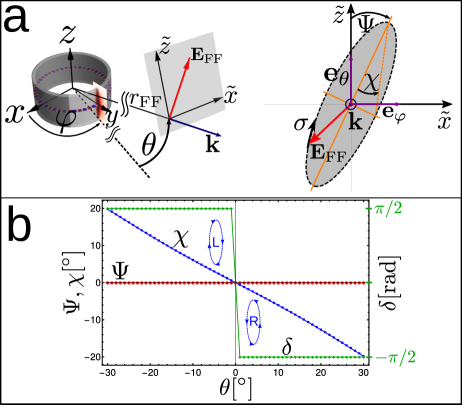
In a local far-field coordinate system , where the -axis and -axis are spanned by and , respectively, the physically observable electric field given by the real part of describes an ellipse in general, see Fig. 1 a. This polarization ellipse is characterized by (i) the orientation angle of its major axis with respect to the -axis, (ii) the ellipticity angle (with minor axis/major axis) and (iii) the handedness of the direction of rotation of when looking against the propagation direction (looking towards the resonator), see Fig. 1.
The quantities , and are given by Collett (2005):
| (8) | ||||
| (9) | ||||
| (10) |
where is the ratio of the amplitudes of the far-field components and , and represents the phase difference between and .
The angle describes the tilt with respect to the local -axis and ranges from to . and correspond to vertical (parallel to the -axis) and horizontal (parallel to the -axis) polarization orientation, respectively.
The ellipticity angle describes the states of linear (), elliptical () and circular () polarization. The sign of corresponds to the sign of the phase difference because of the -term in Eq. (9). and represent right-handed () and left-handed () polarization, respectively.
The desired relation between the fields inside the ring resonator and the far-field components is provided by the Kirchhoff diffraction theory that we explain in more detail in the Supplemental material. To this end we treat the side wall of the 3D ring resonator as aperture that diffracts the fields of the WGM resonances into the far field. Due to the thin-wall structure, we approximate the 3D-Ring by a cylinder surface of radius and height . The electric far-field vector can be computed by evaluating Kirchhoff’s vector diffraction formula in the Fraunhofer (or far-field) limit Jackson (1998) yielding
| (11) |
where is the position vector on the diffracting surface with area element and electric field , is the unit vector normal to the surface, and k the far-field wave vector. Note that only fields parallel to the surface (represented by the term in Eq. (11) are considered. Contributions from normal field components, , which would show up as an additional magnetic field term inside Eq. (11),
were neglected because the predominantly TE-like character of the WGM resonances ensures the electric field components to be parallel to the resonator wall and thus parallel to the diffracting surface .
The fields at the cylindrical diffracting surface can be represented as .
Evaluating the diffraction formula Eq. (11), we obtain the sought-after expressions for the far-field components and (see SM),
| (12) | ||||
| (13) |
where the are the Bessel functions of the first kind with and . and represent the following expressions using :
| (14) | ||||
| (15) |
where Eq. (14) resembles the diffraction pattern of a slit of height with the local amplitude . Due to the strong confinement, the amplitude rapidly converges towards zero above and below the wall of the ring as shown in Fig. 2 and, therefore, can be interpreted as the Fourier transform of .
Eq. (15) describes an additional term taking the amplitude at the upper and lower boundary into account where represents the axial mode number, cf sec. II. It arises from integration by parts of the component ( ), cf. supplemental material.
For the sake of simplicity, we neglect the boundary amplitude in Eq. (15) for the fundamental axial mode (), . As a result, and
we see that the and components of the far field (Eqs. 12 and 13) are directly connected to the Fourier transform of the component of the WGM field at the resonator wall. Furthermore, the component changes its sign at because of the term which indicates far-field polarization states of opposite handedness for and .
Remarkably, the polarization quantities and of the fundamental axial mode () are independent of the far-field pattern represented by because this term cancels out in the parameter and it is also irrelevant for the phase difference . Thus, the spatial splitting of the handedness of the far-field polarization states, as illustrated in Fig. 1 b, is an intrinsic feature of a propagating (non-standing) WGM.
For higher axial modes (), the contribution of increases because of increasing boundary amplitudes, cf. Fig. 2, and will enhance the ellipticity as shown in the results further below. The fundamental feature of spatial splitting of the far-field polarization handedness is also enhanced.
II Cylindrical 3D-ring resonators
We begin our study
of spin-orbit interaction of light in a 3D-ring resonator cavity with mean radius , wall thickness and height . The electromagnetic eigenmodes of such cavities are WGMs (hosted in the cavity cross section) subject to the additional confinement in -direction, see Fig. 2 a. The field pattern of exhibits different types of excitations that can be characterized by the axial mode number representing the number of extrema of along the resonator height.
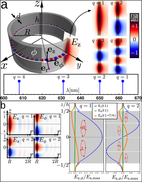
Fig. 2 a illustrates the ring geometry and slices of the 3D field distribution at (showing the radial distribution of the field) and at (showing its vertical distribution).
The field distributions are taken from a temporal snapshot of a clock-wise propagating wave with and . The panel on the right-hand side shows the fundamental vertical excitation and the lower panel
their spectral positions, indicating that the wavelength decreases with increasing excitation as expected.
The diagrams on the right-hand side of Fig. 2 b show the transverse and the longitudinal
component of the electric field of the fundamental mode and the first vertical excitation at two different time steps, and with being the optical period. The fields are taken along the center of the wall (), c.f. the insets on the left-hand side.
We see that the graphs of correspond to the derivative of , cf. Eq. (5). Furthermore, we see that reaches its maximum a quarter period later than because of the factor resulting from the confinement of the propagating mode, cf. Sec. 1. This phase shift of generates elliptical polarization inside the ring resonator as illustrated by the red ellipses. Note that the polarization ellipse lies in a plane spanned by and , that is the polarization ellipse lies parallel to the propagation direction.
The upper (lower) half of the -WGM carries right (left)-handed elliptical polarization where right (left)-handed elliptical or circular polarization is defined by opposite (same) sign of the and components.
As we shall see below, precisely this splitting is transferred into the far-field and can be observed there. The -WGM has 4 regions (separated by horizontal dashed lines in Fig. 2 b) of alternating right and left-handed polarization. We point out that elliptical polarization
occurs in traveling waves only whereas in standing wave WGMs the transverse spin-momenta of the counter-propagating modes cancel exactly and yield linear polarization.
In the next step, we will investigate how the far-field polarization state depends i) on the far-field (observation) angle and ii) on the vertical excitation number .
The far fields were obtained by computing the far-field electric field vectors and its far-field components and in a distance of from the origin, see inset of Fig. 3 a. The angles are the azimuthal and elevation angle of the far field, respectively. The far-field polarization states are characterized by the orientation angle , the ellipticity angle and the handedness , cf. Fig. 1 a.
Due to the rotational symmetry around the z-axis, the -dependence is trivial and thus we focus on the -dependence of the far field.
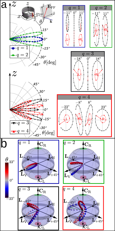
Fig. 3 a shows the far-field intensity as polar plot for and , respectively. We find that corresponds directly to the number of observed far-field lobes. This connection can be explained by Fraunhofer (far-field) diffraction where the wall of the resonator acts as an aperture, see Eq. (11). The dominant -component of the WGM resonance will also rule the far-field pattern.
In Fig. 3 a the far-field electric field vector in the local - coordinate system is shown at the elevation angles with maximum far field emission (and for ) indicated on top of each frame. From top to bottom, the cases are shown. The electric field vectors are taken over one oscillation period where the red arrows and black dots correspond to the phase-dependent position of the first snapshot and the 19 following snapshots of the oscillation period, respectively.
In the case of the -WGM, we observe left (right)-handed elliptical polarization for negative (positive) far-field angles and linear polarization at the lobe maximum at . This separation of the polarization handedness in the far-field arises from the reversed polarization distributions inside the resonator, cf. Fig. 2 b. The maximum of the lobe at shows linear polarization because the -plane is a symmetry (mirror) plane at which the opposite handed polarization states compensate each other, resulting in linear polarization pointing into the -direction, i.e. . Similar results of polarization separation in the far field were observed for scattering of surface plasmons at nanostructures O’Connor et al. (2014).
The far field of the -WGM has two pronounced lobes with opposite polarization handedness and stronger elliptical polarization compared to the -case. The more pronounced elliptical polarization arises from the stronger confinement along the -direction of the mode, and hence a stronger spin-orbit interaction generating a stronger component as shown in Fig. 2 b (maximum of for reaches almost , where as for remains below ). The two far-field lobes arise from the dominant component, cf. Fig. 2 b, whereas the opposite handedness results from the opposite polarization distribution inside the resonator.
For , the far field is very similar to the one of because in both cases it has an even and odd distribution inside the resonator. The stronger pronounced elliptical polarization arises from the now even stronger confinement as explained for -case.
Eventually, the far field of the -WGM shows 4 lobes of alternating polarization handedness and switching ellipticity. The outer lobes show almost circular polarization. The polarization orientation of the inner lobes is slightly tilted from the -axis.
In order to further characterize the polarization states, we use their
- and -values to present them on the so-called Poincaré-sphere of polarization Collett (2005), cf. Fig. 3 b. The sphere is spanned by and which represent the azimuthal and elevation angle, respectively. The equator of this sphere () corresponds to linear polarization states of different orientations: - linear vertical (), - linear horizontal (), and - linear inclined by (). The poles of the Poincaré-sphere at correspond to right-handed () and left-handed () circular polarization. All other states indicate elliptical polarization. The distance from the origin indicates the
far-field intensity
The Poincaré-spheres in Fig. 3 b illustrate the observable far-field polarization states when scanning the far-field through the color-encoded -range. For the polarization handedness is directly related to different spatial regions as is clearly visible by the blue (red) points remaining in the lower (upper) hemisphere.
We emphasize that the far-field polarization ellipse lies in a plane spanned by and and is transverse to the propagation direction , whereas the polarization ellipse inside the resonator is longitudinal to the propagation direction . Thus, we observe a transition from a longitudinal to transverse polarization ellipse orientation in the far field.
III Cone-like 3D ring resonators
We shall now investigate the role of inclined resonator walls in order to understand 3D systems like cone-like tube-cavities or realistic (imperfect) 3D microresonators. The inclination angle of the resonator wall with respect to the -axis is illustrated in the inset of Fig. 4 a. Choosing breaks the symmetry with respect to the -plane. As a consequence, we expect that the modes inside the resonator and the far-field lobes will display an asymmetry as well. Analyzing this behaviour is crucial for all applications where the far field is taken as the sensing signal.
In the following, we will study this key question focussing on -modes.
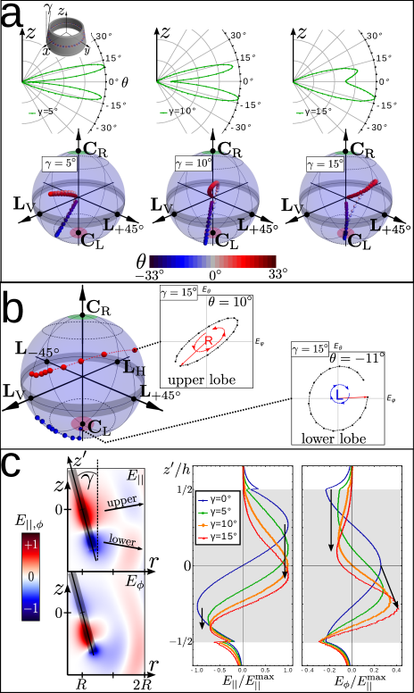
The upper row in Fig. 4 a shows the polar far-field plots for three inclination angles . The lower row shows the corresponding Poincaré-spheres of polarization displaying all observable polarization states when scanning the far field through the color-encoded -range from to .
A small wall inclination of causes a rather slight asymmetry in the maximum intensity of the lobes while the shape of the far-field lobes is maintained and polarization orientation is only slightly tilted (shifted along the equator of the Poincaré) sphere, cf. Fig. 3 b).
However, for higher inclination angles the far-field intensity and the shape of the polarization evolution change strongly both in terms of visible asymmetries in the far-field lobes and evolution on the Poincaré sphere.
Fig. 4 b shows the Poincaré-sphere of the polarization states at the far-field intensity maxima for different inclination angles between and . The red (blue) dots correspond to the upper (lower) lobes. The points right above and below correspond to . Via points at the end point at , indicated by the polarization ellipse insets, is reached. Interestingly, the upper and lower lobes experience a different polarization evolution. The polarization states of the upper lobe remain elliptically polarized but experience a strong orientation tilt. In contrast, the polarization states of the lower lobe evolve from slightly elliptical to left-hand circular polarization.
The tilt of the polarization orientation can be explained and deduced from the vector diffraction model introduced in Eq. (11) where we treat the wall of the resonator as an aperture that diffracts the waves inside the resonator into the far field. See section I.B. of the SM for more details and derivation of the following formulas. The far-field components and in the case of cone-like 3D ring cavities can be written as
| (16) | ||||
| (17) |
where and represent the far-field components that arise from the diffraction of a 3D ring structure, cf. Eq. (23) of the SM and Eqs. (24)-(27) of the SM. The additional terms that include and exist only for (conical cavities) and arise from the precession of the electric field along its trajectory around the cone axis, cf. Eq. (23) of the SM. The precession terms are phase shifted by w.r.t. the ring diffraction terms as indicated by the prefactor . As a consequence, both components and undergo a phase change which increases with increasing inclination angle . This is the very origin of the phase between the far-field components and which in turn results in a change of the orientation angle , cf. Eq. (8). This explains the general feature of the increasing tilt angle with increasing inclination angle as shown in Fig. 4 b.
The different evolution of the upper and lower lobes can be explained by an asymmetric distortion of the amplitudes. By inclining the resonator wall, the mirror symmetry at the - plane is broken. Thus, we expect that the electric field amplitudes and inside the resonator wall undergo a distortion. The left panels of Fig. 4 c show an example of such a distorted electric field. The panels on the right-hand side of Fig. 4 c display a comparison of and at for different inclination angles where and correspond to the field distribution along the -axis (at half wall thickness) and the longitudinal -component as indicated in the panels on the left-hand side.
First of all, we notice that the entire distributions of and shift more towards the broader end of the cone (into the negative -direction) with increasing . Using the graph of at as an example, we see (i) that for decays to zero inside the cavity and (ii) that the distance between the maximum and minimum is compared to . These facts indicate that the confinement length scale along the height of the resonator wall is reduced. As a result, the longitudinal component increases because of . The increase of at is noticeable through the increase of the height of the central maximum as indicated by the black arrow. Thus, the overall spin-orbit interaction is enhanced and explains the generally increasing ellipticity with increasing .
Concerning the lobe asymmetry, we use again the graph of at as an example. We see that the maximum () shifts by an larger distance than the minimum () as indicated by the black arrows. As a result, the upper part of the distribution is stretched while the lower part is compressed (asymmetric distortion). The stretching extends the confinement length scale locally and therefore, the spin-orbit coupling is reduced within this length scale. On the other hand, the compression reduces the confinement length scale locally and therefore, the spin-orbit coupling is enhanced within this length scale. This allows us to qualitatively explain the behaviour of the far-field polarization states of the two different lobes shown in Fig. 4 b. As a result, the lower far-field lobes (blue points) emerging from the lower part of the distorted field distribution show an increased ellipticity with respect to the upper far-field lobes (red points) that emerge from the upper part of the distorted field distribution.
The property of asymmetrical distortion of the amplitudes is linked to the far-field components and via the diffraction integral. We exemplarily show this for . According to the derivations in the SM (cf. Eq. (24) in SM), is given by:
| (18) |
where , and are the components of the ring diffraction integral. For example, is given by:
| (19) |
where is a function resulting from the integration, cf. Eq. (39) of the SM. Note that the -integration can not be treated approximately as a mere Fourier-Transform of the amplitudes as in the case of the 3D-ring, cf. Eq. (14).
We point out that Eqs. (16) and (17) provide a formula which takes the effects of diffraction and precession of the electric field into account. These effects determine the orientation angle and the ellipticity , cf. Eqs. (8) and (9). Especially important is that , and the handedness depend on the far-field observation direction which is described by the angles and . We would like to highlight that the quantities and are observable in the far field, but the WGM inside the resonator wall has a different and complicated polarization state. The connection between the polarization state of the WGM and the observable far-field quantities is provided by diffraction and precession.
In Ma et al. (2016), an inclination of the far-field polarization orientation and an increase of the ellipticity was experimentally observed for inhomogeneous anisotropic cone-like cavities and explained in terms of non-cyclic geometric phases. Here, we find a similar behavior in the generic case of homogeneous isotropic cavities and an explanation in terms of diffraction theory.
IV Complex cone-like tubular cavities
We have seen in the previous sections that the spin-orbit interaction of light depends sensitively on the confinement of light that is determined both by the resonator geometry and the specific resonance pattern. To further illustrate this intricate interplay, we will now study complex, composite 3D cone-like tubular cavities where the confining region of the cavity is extended by an additional layer of cavity material, see Fig. 5 a. This resonator wall geometry is inspired by rolled-up cones where regions of different wall thicknesses emerge, e.g. cf. Strelow et al. (2007); Bolaños Quiñones et al. (2012); Ma et al. (2016) and by cavities where an extra layer of material results from an etching process, cf. Strelow et al. (2012).
The confining region is realized by two different axial profiles, a rectangular profile (rp) and triangular profile (tp), as shown on the right-hand side of Fig. 5 a. We consider cone-like cavities with a mean diameter and total height . We will investigate the far-field polarization states and how they depend on (i) the confining profile and (ii) the inclination angle of the tube wall. The results are shown in Fig. 5 b. The far-field polarization states of maximum intensity of -modes confined in 5 different axial profiles are shown on the Poincaré sphere with its upper (lower) hemisphere corresponding to the upper (lower) lobes. The yellow arrow indicates the generic polarization evolution for increasing inclination angle (again, with the data points closest to the longitude of corresponding to ). We observe the general feature that with increasing the polarization states evolve into the direction of while getting closer to the poles of the sphere. In other words, orientation tilt and the ellipticity increase with increasing wall inclination. This behaviour is very similar to the one observed before, cf. Fig. 4 b.
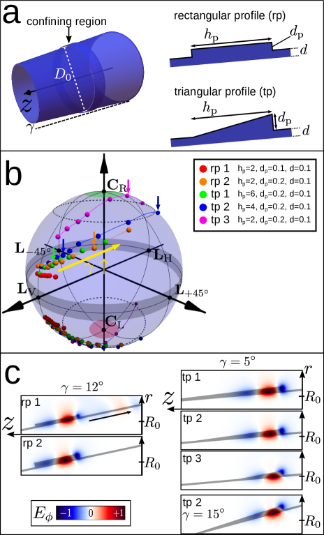
The evolution of the polarization state depends on the confining profile that in turn controls the mode’s axial field distribution,
and hence, following Eq. (5), the spin-orbit interaction. In case of the rectangular profile, the far-field polarization states depend strongly on the thickness of the profile as represented by the red (rp 1) and orange (rp 2) data points on the Poincaré sphere in Fig. 5 b. The inclination angles of the rectangular profile 1 range from up to in steps of one degree. For higher angles than the modes become unstable and propagate downwards (towards the broader end of) the cone because the confining profile is too thin to stably host a WGM resonance. This finding is illustrated on the left-hand side of Fig. 5 c. The upper (lower) image shows a section around the confining region rp 1 (rp 2) for , overlaid with the electric field component obtained from FDTD simulations.
We clearly see that a wave packet is leaving the profile rp 1 and propagating towards the broader part of the cone (black arrow). This indicates an unstable mode and no stationary far-field polarization states can be found. Contrary to this, the thicker profile rp 2 ensures the existence of a stable WGM-type resonance, see the lower left panel in Fig. 5c that corresponds to the state marked by an orange arrow on the Poincaré sphere in Fig. 5 b.
The upper three images on the right-hand side of Fig. 5 c compare the electric field distribution at different configurations of the triangular profile tp 1, tp 2 and tp 3 but all at constant wall inclination angle . The corresponding far-field polarization states are marked by a green (tp 1), blue (tp 2) and magenta (tp 3) arrow on the
Poincaré sphere of Fig. 5 b. We see that the difference between the field distribution in tp 1 and tp 2 is small. As a consequence the corresponding far-field polarization states are located in close proximity on the Poincaré sphere, cf. Fig. 5 b. The highlighted polarization state corresponding to tp 2 shows a slightly higher tilt and ellipticity because the profile tp 2 provides stronger confinement, and hence stronger spin-orbit interaction due to the reduced profile height .
On the other hand, the difference between the field distributions in tp 2 and tp 3 is more pronounced due to the further reduced profile height of tp 3. The distribution is now visibly characterized by a strong mode distortion
that causes a higher spin-orbit interaction. As a result, the corresponding far-field polarization state of tp 3 (highlighted by the magenta arrow on the Poincaré sphere in Fig. 5 b) is almost circularly polarized.
For comparison, the lowest panel on the right-hand side of Fig. 5 c shows the distribution of tp 2 at the higher inclination angle of . Interestingly, this distribution is very similar to that of tp 3 because it displays a similar distortion, confer the red areas of the distributions. We conclude that the high inclination angle of of tp 2 results in a comparable confinement and distortion of the mode as caused by the profile tp 3 at lower angle. As a result the corresponding far-field polarization states display similar features indicated by the dark blue and magenta arrow on the Poincaré sphere.
The overall increasing tilt of the polarization orientation and ellipticity caused by the triangular profiles result from a enhanced precession of the electric field and a stronger spin-orbit coupling, respectively. The stronger spin-orbit coupling can be explained by an increased axial confinement. The enhanced precession of the electric field can be explained by an increased effective inclination angle . In addition to the inclined cone wall described by , the triangular profile provides a further local inclination given by . The interplay of both inclinations leads to and thus,
according to the introduced diffraction model, an increased inclination angle leads to an increased tilt of the polarization orientation.
V Summary
We have performed FDTD simulations in order to investigate the spin-orbit coupling of light in three-dimensional cylindrical and tube-like whispering gallery mode resonators.
We have shown that the spin-orbit interaction in cylindrical ring cavities results in elliptical far-field polarization and spatial separation of left and right elliptically polarized light in the far field but without tilting of the orientation angle. The ellipticity and spatial polarization separation of the far field is more pronounced in axially higher excited whispering gallery modes due to increased spin-orbit coupling.
Furthermore, we have shown that the inclination of the resonator wall realized by cylindrical ring-like cone-cavities enhances the ellipticity of the far field further and induces a tilt of the far-field polarization orientation even for homogeneous and isotropic material systems. The enhancement of the far-field ellipticity arises from the asymmetric distortion of the electric field distribution at the resonator wall. This asymmetric distortion causes different elliptical polarization states of upper and lower far-field lobes. The tilt of the polarization orientation arises from the precession of the electric field vector along its trajectory around the cone axis. The connection between the local polarization state of the whispering gallery mode inside the resonator and the observable far-field quantities is provided by the introduced diffraction model. We emphasize that the polarization orientation , the ellipticity and the handedness depend on the direction of observation described by the far-field angles .
In the end, we have investigated complex cone-like tubular cavities with different confining profiles. Similar to the case of ring-like cone-cavities, the tilt of the polarization orientation and the ellipticity increase with increasing wall inclination . Furthermore, we have discovered that a triangular profile enhances the tilt of the orientation and the ellipticity because of an increased effective inclination and a stronger spin-orbit coupling, respectively.
Our results demonstrate the importance and variety of spin-orbit coupling of light in three-dimensional whispering gallery mode resonators as a fundamental effect and may be important for optical information technology or polarization dependent sensing applications.
FDTD-Method
All data presented in this work was obtained from FDTD-calculation based on the open source software package MEEP Oskooi et al. (2010).
We give a short description of the procedure: In the first step, we have computed the resonance frequencies of TE-like modes for the following structures: 3D-ring cavities (cf. section II) , cone-like ring cavities (cf. section III) and cone-like tubular cavities (cf. section IV).
In the second step, we have computed the electric field distribution of the resonances and let the fields evolve for one period in order to make 20 snapshots of the electric field in the region around the cavity (near field).
In addition to this, we computed 20 snapshots of the electric field on a circular arc with radius of (approximately satisfying the far-field condition ) within the range of in steps of . These far-field snapshots were used to calculate (as a measure of the far-field intensity) and the orientation angle and the ellipticity angle of the polarization ellipse. The handedness was determined by the rotation sense of the electric field vector describing the polarization ellipse. Please note that due to the cylindrical symmetry of the considered structures we have used cylindrical coordinates in MEEP. As a result, the computed fields have the form and thus they represent azimuthally propagating fields.
Acknowledgements.
This work was partly supported by Emmy-Noether programme of the German Research Foundation (DFG).References
- Yamamoto and Slusher (1993) Y. Yamamoto and R. E. Slusher, Physics Today, edited by A. J. C. R. K. Chang, Vol. 46 (World Scientific, Singapore, 1993) pp. 66–73.
- Vahala (2003) K. J. Vahala, Nature 424, 839 (2003).
- Collot et al. (1993) L. Collot, V. Lefèvre-Seguin, M. Brune, J. M. Raimond, and S. Haroche, EPL 23, 327 (1993).
- Gorodetsky et al. (2000) M. L. Gorodetsky, A. D. Pryamikov, and V. S. Ilchenko, J. Opt. Soc. Am. B 17, 1051 (2000).
- Vollmer et al. (2012) F. Vollmer, L. Yang, and S. Fainman, Nanophotonics 1, 267 (2012).
- Ilchenko et al. (2001) V. S. Ilchenko, M. L. Gorodetsky, X. S. Yao, and L. Maleki, Opt. Lett. 26, 256 (2001).
- Armani et al. (2003) D. K. Armani, T. J. Kippenberg, S. M. Spillane, and K. J. Vahala, Nature 421, 925 (2003).
- McCall et al. (1992) S. L. McCall, A. F. J. Levi, R. E. Slusher, S. J. Pearton, and R. A. Logan, Appl. Phys. Lett. 60, 289 (1992).
- Michael et al. (2007) C. P. Michael, K. Srinivasan, T. J. Johnson, O. Painter, K. H. Lee, K. Hennessy, H. Kim, and E. Hu, Appl. Phys. Lett. 90, (2007).
- Sumetsky (2004) M. Sumetsky, Optics Letters 29, 8 (2004).
- Strelow et al. (2007) C. Strelow, C. M. Schultz, H. Rehberg, H. Welsch, C. Heyn, D. Heitmann, and T. Kipp, Physical Review B - Condensed Matter and Materials Physics 76, 1 (2007).
- Strelow et al. (2008) C. Strelow, H. Rehberg, C. M. Schultz, H. Welsch, C. Heyn, D. Heitmann, and T. Kipp, Physical Review Letters 101, 1 (2008).
- Li et al. (2009) F. Li, S. Vicknesh, and Z. Mi, Electronics Letters 45, 645 (2009).
- Strelow et al. (2012) C. Strelow, C. M. Schultz, H. Rehberg, M. Sauer, H. Welsch, A. Stemmann, C. Heyn, D. Heitmann, and T. Kipp, Physical Review B - Condensed Matter and Materials Physics 85, 1 (2012).
- Ma et al. (2016) L. B. Ma, S. L. Li, V. M. Fomin, M. Hentschel, J. B. Götte, Y. Yin, M. R. Jorgensen, and O. G. Schmidt, Nature Communications 7, 4 (2016).
- Huang and Mei (2017) G. Huang and Y. Mei, Journal of Materials Chemistry C 5, 2758 (2017).
- Wang et al. (2019) J. Wang, Y. Yin, Y. D. Yang, Q. Hao, M. Tang, X. Wang, C. N. Saggau, D. Karnaushenko, X. Yan, Y. Z. Huang, L. Ma, and O. G. Schmidt, ACS Photonics 6, 2537 (2019).
- Lacey and Wang (2001) S. Lacey and H. Wang, Optics Letters 26, 1943 (2001).
- Schwefel et al. (2005) H. G. L. Schwefel, A. D. Stone, and H. E. Tureci, Journal of the Optical Society of America B 22, 2295 (2005).
- Teraoka and Arnold (2006) I. Teraoka and S. Arnold, Journal of the Optical Society of America B 23, 1381 (2006).
- Kreismann et al. (2017) J. Kreismann, S. Sinzinger, and M. Hentschel, Physical Review A 95, 1 (2017).
- Kreismann and Hentschel (2018) J. Kreismann and M. Hentschel, EPL (Europhysics Letters) 121, 24001 (2018).
- Gladyshev et al. (2018) S. A. Gladyshev, A. A. Bogdanov, P. V. Kapitanova, M. V. Rybin, K. L. Koshelev, Z. F. Sadrieva, K. B. Samusev, Y. S. Kivshar, and M. F. Limonov, Journal of Physics: Conference Series 1124, 51058 (2018).
- Khosravi et al. (2019) F. Khosravi, C. L. Cortes, and Z. Jacob, Optics Express 27, 15846 (2019).
- Bliokh and Nori (2015) K. Y. Bliokh and F. Nori, Physics Reports 592, 1 (2015).
- Aiello et al. (2015) A. Aiello, P. Banzer, M. Neugebauer, and G. Leuchs, Nature Photonics 9, 789 (2015).
- Cardano and Marrucci (2015) F. Cardano and L. Marrucci, Nat Photon 9, 776 (2015).
- Junge et al. (2013) C. Junge, D. O’Shea, J. Volz, and A. Rauschenbeutel, Physical Review Letters 110, 1 (2013), arXiv:1301.1659 .
- O’Connor et al. (2014) D. O’Connor, P. Ginzburg, F. J. Rodríguez-Fortuño, G. A. Wurtz, and A. V. Zayats, Nature Communications 5, 1 (2014).
- Shao et al. (2018) Z. Shao, J. Zhu, Y. Chen, Y. Zhang, and S. Yu, Nature Communications 9, 1 (2018), arXiv:1709.09811 .
- Eismann et al. (2019) J. S. Eismann, P. Banzer, and M. Neugebauer, Physical Review Research 1, 1 (2019), arXiv:1905.12539 .
- Rosenberger et al. (2019) A. T. Rosenberger, E. B. Dale, K. V. Bui, E. K. Gonzales, D. Ganta, L. Ke, and S. R. Rajagopal, Optics Letters 44, 4163 (2019).
- Sun et al. (2019) L. Sun, B. Bai, J. Wang, M. Zhang, X. Zhang, X. Song, and L. Huang, Advanced Functional Materials 29, 1902286 (2019).
- Berry (1984) M. V. Berry, Proceedings of the Royal Society of London A: Mathematical, Physical and Engineering Sciences 392, 45 (1984).
- Berry (1987) M. V. Berry, Nature 326, 277 (1987).
- Bliokh et al. (2008) K. Y. Bliokh, A. Niv, V. Kleiner, and E. Hasman, Nature Photonics 2, 748 (2008), arXiv:0810.2136 .
- Bliokh et al. (2019) K. Y. Bliokh, M. A. Alonso, and M. R. Dennis, Reports on progress in physics. Physical Society (Great Britain) 82, 122401 (2019), arXiv:1903.01304 .
- Loss et al. (1990) D. Loss, P. Goldbart, and A. V. Balatsky, Physical Review Letters 65, 1655 (1990).
- Nagasawa et al. (2013) F. Nagasawa, D. Frustaglia, H. Saarikoski, K. Richter, and J. Nitta, Nature Communications 4 (2013), 10.1038/ncomms3526.
- Frustaglia et al. (2001) D. Frustaglia, M. Hentschel, and K. Richter, Phys. Rev. Lett. 87, 256602 (2001).
- Hentschel et al. (2004) M. Hentschel, H. Schomerus, D. Frustaglia, and K. Richter, Phys. Rev. B 69, 155326 (2004).
- Jackson (1998) J. D. Jackson, ed., Classical Electrodynamics, 3rd ed. (Wiley, New York, 1998).
- Bolaños Quiñones et al. (2009) V. A. Bolaños Quiñones, G. Huang, J. D. Plumhof, S. Kiravittaya, A. Rastelli, Y. Mei, and O. G. Schmidt, Optics Letters 34, 2345 (2009).
- Bolaños Quiñones et al. (2012) V. A. Bolaños Quiñones, L. Ma, S. Li, M. Jorgensen, S. Kiravittaya, and O. G. Schmidt, Optics Letters 37, 4284 (2012).
- Collett (2005) E. Collett, Field Guide to Polarization (SPIE Press, Bellingham, 2005).
- Oskooi et al. (2010) A. F. Oskooi, D. Roundy, M. Ibanescu, P. Bermel, J. D. Joannopoulos, and S. G. Johnson, Computer Physics Communications 181, 687 (2010).