Sign-reversal electron magnetization in Mn-doped semiconductor structures
Abstract
The diversity of various manganese types and its complexes in the Mn-doped semiconductor structures leads to a number of intriguing phenomena. Here we show that the interplay between the ordinary substitutional Mn acceptors and interstitial Mn donors as well as donor-acceptor dimers could result in a reversal of electron magnetization. In our all-optical scheme the impurity-to-band excitation via the Mn dimers results in direct orientation of the ionized Mn-donor shell. A photoexcited electron is then captured by the interstitial Mn and the electron spin becomes parallel to the optically oriented shell. That produces, in the low excitation regime, the spin-reversal electron magnetization. As the excitation intensity increases the capture by donors is saturated and the polarization of delocalized electrons restores the normal average spin in accordance with the selection rules. A possibility of the experimental observation of the electron spin reversal by means of polarized photoluminescence is discussed.
Introduction. The control of a spin state and the related magnetization of the charge carriers by nonmagnetic methods is a key concept of the semiconductor spintronics. A reversal of the magnetization by electrical or optical means may help construct the low-power spintronic devices eliminating the conventional magnetic switching method. The manipulation of magnetization by the electric field or current is well known both in nonmagnetic Silov et al. (2004) and in magnetic semiconductors (e.g., GaMnAs) Matsukura et al. (2015); Lee et al. (2017) and in hybrid semiconductor/ferromagnetic structures Tivakornsasithorn et al. (2018).
The absorption of the circularly polarized light leads to the spin polarization of the nonequilibrium carriers in the semiconductor structures due to spin-orbit interaction. Thus, the optical orientation Meier and Zakharchenya (1984); Dyakonov (2008) is simply the conservation of angular momentum in a system of the electrons and the photons. It is well known that the optical selection rules strictly couple a photon polarization with the electron spin state during the photoexcitation. However, in a steady state it is necessary to take into account not only the excitation processes (selection rules) but also the relaxation processes as well.
Usually the spin state of nonequilibrium charge carriers is determined experimentally by means of the polarized photoluminescence (PL). The so-called “negative” PL polarization (the PL polarization helicity is opposite to that of an excitation) does not necessarily indicate the reorientation of the photoexcited spin. Moreover, this frequently corresponds to the recombination of the resident carrier whose spin is aligned due to the exchange interaction with an exciton (see, for instance, Ref. Ignatiev et al., 2009). Unlike such processes here we suggest a mechanism of the anomalous alignment of the nonequilibrium carrier spin.
A possibility to address individual impurities Koenraad and Flatte (2011) by optical methods holds considerable promise Léger et al. (2006); Kudelski et al. (2007). The direct manipulation of the impurity spin via the impurity-to-band excitation (the photoneutralization transition) has an advantage in that respect compared to the band-to-band one. The optical transitions involving impurities are well known from the early 1960s Eagles (1960); Dumke (1963). The possible use of these transitions for the optical orientation was recently discussed Kokurin et al. (2013) and experimentally demonstrated Petrov et al. (2016).
In this communication a possibility to change the magnitude and the sign of the electron magnetization in the Mn-doped GaAs structures by optical means alone is foretold. A model describing a possibility to govern the electron spin magnetization by utilizing the impurity-to-band excitation scheme is proposed. The magnetization is described by a system of rate equations involving the conduction band electrons and various Mn complexes. We also consider an experimental implementation of our findings.
Rate equations and electron sign-reversal magnetization. – Our model takes into account the following Mn complexes. The conventional Mn acceptor substituting Ga-cation in GaAs lattice (see a recent review Averkiev and Gutkin (2018), and references therein) is referred to as . Double donors arising in the interstitial positions are taken into consideration as well Máca and Mašek (2002); Yu et al. (2002). It is essential that the closely spaced ionized donors and acceptors can form pairs or (-)-dimers Dietl and Ohno (2014).
Let us consider the optical orientation through the photoneutralization transition (excitation from an ionized acceptor state to the conduction band) in Mn-doped GaAs structures. Such a transition, , with the excitation energy less than a band gap in the case of deep acceptors ( ionization energy in bulk GaAs is about 110 meV) can be realized in compensated structures only 111Using the structures with the quantum wells has an additional advantage of the complementary compensation from the donors in the barriers of the modulation-doped structures.. The presence of various Mn types and complexes and accounting of exchange interaction specifics therein provides the possibility for the electron sign-reversal magnetization (SRM) in the system of photoexcited electrons.
The kinetic scheme for SRM is shown in Fig. 1. The above-mentioned configurations of the manganese and their different charged states are taken here into account. In equilibrium there are both acceptors and donors in the ionized states and , respectively. Their relative concentration depends on the compensation degree. Both of these charge states will be classified by the total shell spin of . The interstitial Mn donor can also capture an extra electron forming a very shallow donor state Dietl and Ohno (2014). The exchange interaction of the electron and the shell is ferromagnetic in this case (the ground state with the total angular momentum of 3). The exchange interaction of the shell and the acceptor bound hole (the angular momentum Gel’mont and D’yakonov (1972); Baldereschi and Lipari (1973)) is antifferomagnetic, which leads to the ground state of with the total angular momentum Averkiev and Gutkin (2018). The exchange interaction between two shells in (-) dimer is antiferromagnetic Blinowski and Kacman (2003); Mašek and Máca (2004), which corresponds to the ground state with the zero magnetic moment.
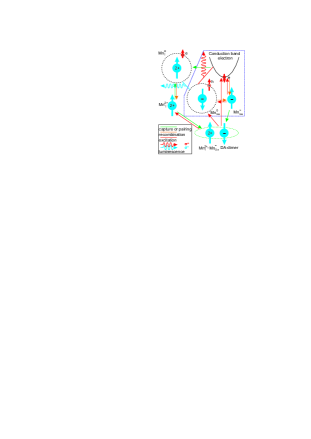
The pseudospin-1/2 model is utilized to describe both and states, which is a sufficient scheme to explain the SRM phenomenon. The following concentrations notation is used in our rate-equation model. Here the thick arrows () correspond to the () projection of shell spin. By analogy () indices point out onto electrons or holes with the spin projection () and (), respectively. For the conduction band electrons () are assigned to the spin-up (spin-down) state. In the ground state of we take into account () for states with () angular momentum projection. The singly ionized donor concentrations with angular momentum projections () are labeled by (). The concentrations () correspond to the states of with the -shell spin (). Similarly () describes the donor state with the -shell spin (). Finally, stands for the (-)-dimer ground state concentration. This leads to the system of rate equations Sup . Each donor is supposed in equilibrium to be a part of the dimer.
Two separate channels of excitation are considered in our scheme (see Fig. 1). The first one is the photoneutralization of the ionized acceptor , and the second one corresponds to the photoneutralization of the ionized acceptor inside the (-) dimer. The excitation acts on the state of ionized acceptors. In the former case the conduction band electron in the state and the neutral acceptor with -shell–hole spin configuration () arise. Furthermore, this leads to predominant -polarization of the remaining ionized acceptors. In the latter case an ionized manganese additionally appears with -polarized shell. The above spin configurations are determined by optical selection rules and the antiferromagnetic alignment between an ionized donor and acceptor inside the Mn dimer. The predominant orientation of leads to spin configuration of after the electron capture by a magnetic donor due to the ferromagnetic alignment.
It is well known that the generation term has the form Ryvkin (1964), where is the absorption coefficient and is the photon flux density. However, for the impurity-assisted transition the absorption coefficient is proportional to the impurity concentration Eagles (1960). We denote the absorption coefficient for the concentration . By analogy the absorption coefficient corresponds to the Mn-dimer concentration . The concentration-independent quantity is (), that is, the absorption cross section. It should be noted that the concentration depends not only on a compensation from , but can additionally increase due to the residual donors with concentration excluded from kinetics, .
Within our pseudospin-1/2 model the electrons in the spin-up and the spin-down state recombine with the hole of the acceptor with the emission of - and -polarized light, respectively. The intensity of the bimolecular recombination is described by and coefficients for the electron-acceptor (eA) and donor-acceptor (DA) recombination, respectively. The capture rate of the photoexcited electrons by the magnetic donors is described by the () coefficient for the process with the spin conservation (spin flip). We consider the dimer formation from single and , which depends on the -shell spin state of the donor and acceptor. The dimer formation rate is determined by the coefficient for the process with the conservation of -shell spins. By analogy the parameter corresponds to the spin-flip process. Here and -shell spins are supposed to be uncorrelated after DA recombination (), i.e., the direct DA-dimer formation during the DA recombination is neglected. For this there are two reasons: (i) the electron of donor can recombine with the hole of center that was not a part of the DA dimer; (ii) the spin configuration of shells of the recombining Mn donor and acceptor is ferromagnetic, which prevents the dimer formation in the ground state. The spin relaxation is taken into account in each charge state with a nonzero angular momentum.
In general, the steady state of the system is described by the system of 11 nonlinear algebraic equations Sup . This problem can be solved only numerically. However, the SRM effect can be qualitatively demonstrated by solving the rate equations in limiting cases of low and high pump power analytically.
At the low pump power, the excitation accompanied by the Mn-dimer decay is dominant, which is the consequence of a higher absorption coefficient 222 in the immediate vicinity of the ionized provides a better spatial overlap of the bound hole and the electrons in the conduction band. In the context of the reciprocity of the absorption and the emission, it leads to a higher absorption coefficient in the DA-dimer state compared to the single ionized acceptor.. Due to the low concentration of recombining carriers in this regime, the radiative lifetime is the longest timescale. In this case the capture by ionized donors is the main mechanism for the decrease of the electron concentrations (). The dominance of the capture mechanism with the electron spin conservation or spin flip depends on the relation between the electron spin relaxation time and the capture time and is governed by the pump power, since the capturing rate is proportional to the ionized donor concentration. In the former case the fast spin relaxation is realized for conduction band electrons, . This corresponds to the capture of relaxed -polarized electrons by -polarized donors. In the latter case we have the opposite situation, . Then predominantly -oriented electrons have to reverse their spin during the capture by polarized (the donor -shell spin-relaxation time is supposed to be long as well). In both cases the spin of the donor-bound electron is oriented oppositely to that of delocalized electrons at the excitation moment.
Thus, in the low pump power regime, the state with the angular momentum projection of predominantly arises (see the left side of the diagram in Fig. 1). Here all excited electrons are supposed to be captured by the donors into the state of . This corresponds to the direct generation term in the rate equation describing the population of the state. Here the capture time (or any terms containing capture parameters , ) is not included in the simplified system of rate equations describing states. Finally, the above scheme can be described by two simplified rate equations for -donor concentration:
| (1) |
| (2) |
Here is the spin-relaxation time. The steady-state solution of these equations in the limit of the fast spin relaxation and the total compensation () gives for the donor concentration and for a difference in population of the opposite spin states the following result:
| (3) |
corresponding to the anomalous magnetization compared to the spin-down polarization under the optical orientation in GaAs. The fast spin relaxation is not a necessary condition to observe the anomalous electron magnetization. Here this assumption is used to reduce the number of variables in equations. On the contrary, the growing spin-relaxation time makes the SRM phenomenon more pronounced (anomalous magnetization grows), which is due to the deceleration of the DA recombination.
In the opposite case of a high pump power the excitation from is dominant due to a saturation of the channel with donors 333The donor concentration does not exceed 10% of the total Mn concentration Dietl and Ohno (2014).. Thus, mainly the right side of the diagram (bordered in Fig. 1) contributes to kinetics. In this case we consider only the equations for conduction band electrons excluding the donor capture Sup :
| (4) |
| (5) |
It is easy to find an analytical result for the high pump power in the limiting case of the fast spin relaxation (). For the steady state the following result for the total concentration and for a concentration difference can be found:
| (6) |
restoring the negative () magnetization that corresponds to a spin alignment in accordance with the selection rules.
The full kinetic picture describing the transition from the positive to the negative magnetization requires both excitation channels of Fig. 1. The magnetization sign depends on a relative contribution of the different excitation channels as well as the competition between the recombination channels (eA and DA recombination). Thus, the concentration dependence of the absorption coefficients and the bimolecular recombination rate lead to a dependence of the electron magnetization on the excitation power. In this case all 11 rate equations are required Sup .
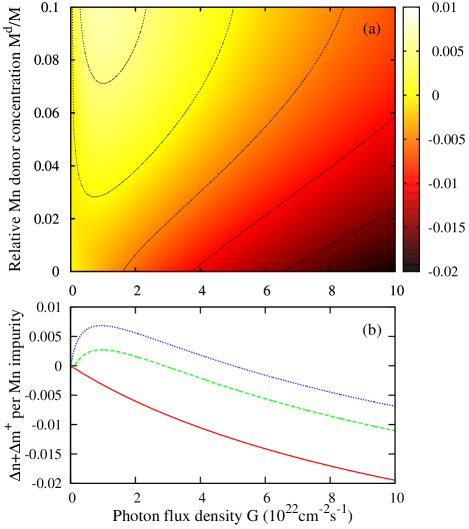
The results of a numerical solution are depicted in Fig. 2, with the dependence of the total electron (both free and localized) polarization being plotted as a function of photon flux density and the relative Mn-donor concentration. In the total kinetic picture we also use the following spin-relaxation times, and for and , respectively. One can see the SRM phenomenon as a function of the excitation power at a nonzero donor concentration. The magnitude of the anomalous (positive) magnetization increases with an increase of the donor concentration ; the pump power corresponding to the change of the magnetization sign increases as well. The relative electron magnetization is higher than the plotted value (, especially at the low pump power when the electron concentration is low, . The magnitude of the effect is not discussed here; only the possibility to invert the electron magnetization by means of the excitation power variation is predicted.
The set of parameters for GaAs with the Mn concentration about cm-3 is used for the numerical solution. The typical value ns Astakhov et al. (2008) is utilized for the conduction band electron spin-relaxation time. The absorption coefficients are close to those of the impurity-to-band transition Eagles (1960). The recombination parameters are of the order of the magnitude known from the literature as well. The estimate of the parameter as cm3s-1 is made based on a result of Ref. Bimberg et al., 1985, where the capture cross section cm2 by a shallow nonmagnetic donor was measured. The electron thermal velocity cm/s for K and GaAs electron effective mass are used as well; . The capture parameter is assumed to be independent on the magnetic nature of the donor. At the low excitation intensity and temperature the captured electron flux is usually higher than the eA recombination one. This is confirmed by the well-known observation of the higher PL intensity of the DA band compared to the eA band. Thus, the relation is usually fulfilled. The spin-relaxation time is assumed to be the longest one, since there is no bound charge carrier at center, whereas, the relaxation of the internal -shell spin provided by the spin-lattice mechanism is slow. The parameters , are free parameters of our model. However, these parameters as well as spin-relaxation times , , and do not affect the SRM effect since they do not enter Eqs. (1), and (2) and the conditions under which these equations are satisfied.
Since the time-dependent system of rate equations includes the coupling between different charge states and Mn complexes, then the magnetization switching time is determined by the longest spin-relaxation time in the system. Thus, the switching time is about ns. It should be noted that the temporal behavior of the electron magnetization is nonmonotonic when the system tends to the steady state.
Discussion of the experimental SRM observation. In practical terms, for the PL excitation spot area of cm2 and photon energy of 1.5 eV, Fig. 2 corresponds to the absorbed pump power of a few tens of microwatts. The experimentally observable quantity characterizing the carrier spin polarization is a degree of the PL circular polarization
| (7) |
where () is the PL intensity with () light polarization. The PL includes both eA- and DA-recombination contribution and for PL-intensity with () polarization one can write
| (8) |
| (9) |
which are the selection rules for radiative recombination. The position of the DA line in the PL spectra relative to the eA line corresponds to the difference of the magnetic donor binding energy (e.g., for the donor in GaAs this energy does not exceed a few meV) and the Coulomb attraction energy in the final state. Thus, the two lines can be unresolved, for which reason we consider the integral polarization of the PL band containing both eA and DA lines.

The calculated dependence of the integral PL polarization as a function of the pump power is plotted in Fig. 3. It has been found by the numerical solution of the system of 11 rate equations Sup and utilizing Eqs. (7)–(9). Qualitatively the total electron spin sign as well as the PL polarization degree depend on a competition between the two above-mentioned channels of the excitation and the recombination. The negative PL polarization at the low pump power corresponds to the predominance of the DA recombination. At the high excitation level the channel via donors is saturated and the sign of the integral PL polarization becomes positive as the eA recombination takes over. The phenomenon is more pronounced for the higher DA-dimer concentration. Nevertheless, the predicted SRM effect persists at any nonzero dimer concentration. The dependence is monotonic as shown in Fig. 3, if the magnetic donor concentration is zero () only.
The estimates for the PL polarization in low/high pump power limits are made. At the fast spin relaxation (, the PL polarization reflects electron magnetization only) the degree of the circular PL polarization in low pump limit () is negative:
| (10) |
In the high pump power limit the PL polarization degree is imposed by the eA recombination, . Due to the predominant spin-down magnetization of the conduction band electrons it is positive and saturated:
| (11) |
with being the radiative lifetime at the high pump power level. The high pump power behavior resembles the well-known result for the PL polarization Meier and Zakharchenya (1984). This formula is similar for the quantum-well case under the excitation/recombination with the participation of the first heavy-hole subband (in the case of the interband excitation/recombination in the bulk material it has to contain prefactor 0.25 as follows from the selection rules). In the present case it is a consequence of a simplification imposed by the pseudospin-1/2 model.
Conclusion. As shown by the proposed consideration, the magnetization in spin subsystems does not depend on the optical selection rules only. The charge-carrier capture by the local defects or impurities, the character of the spin-spin interactions, and the spin relaxation are crucial for the optical orientation as well. The all-optical scheme of the electron sign-reversal magnetization in Mn-doped GaAs-based semiconductor structures has been suggested and extensively studied. We also discuss an experimental way to detect the SRM effect by means of the polarized PL.
The switching of the electron magnetization by means of the temperature control is also possible. Let us consider the above system at the liquid-helium temperature and under the pump power corresponding to the maximal positive magnetization. In this case the magnetization is due to the donor alignment. The growing temperature decreases the capture rate by the shallow donors and in turn the anomalous magnetization is decreased as well. The energy corresponding to the temperature of the liquid nitrogen is about 7 meV, while the electron binding energy of the state in GaAs is estimated as not exceeding 4 meV. The conduction band electrons with such an energy are not captured by donors and predominantly remain in the spin-down state. This means that at the liquid-nitrogen temperature the negative magnetization is almost completely restored.
Acknowledgments. We are grateful to I.V. Rozhansky for useful discussions. I.A.K. and N.S.A. acknowledge financial support from the Russian Science Foundation (Grant No. 17-12-01182-c).
References
- Silov et al. (2004) A. Y. Silov, P. A. Blajnov, J. H. Wolter, R. Hey, K. H. Ploog, and N. S. Averkiev, Appl. Phys. Lett. 85, 5929 (2004).
- Matsukura et al. (2015) F. Matsukura, Y. Tokura, and H. Ohno, Nat. Nanotechnol. 10, 209 (2015).
- Lee et al. (2017) S. Lee, T. Yoo, S.-K. Bac, S. Choi, H. Lee, S. Lee, X. Liu, J. Furdyna, and M. Dobrowolska, Curr. Appl. Phys. 17, 801 (2017).
- Tivakornsasithorn et al. (2018) K. Tivakornsasithorn, T. Yoo, H. Lee, S. Lee, S. Choi, S.-K. Bac, K. J. Lee, S. Lee, X. Y. Liu, M. Dobrowolska, and J. K. Furdyna, Sci. Rep. 8, 10570 (2018).
- Meier and Zakharchenya (1984) F. Meier and B. P. Zakharchenya, eds., Optical Orientation (Amsterdam: North Holland, 1984).
- Dyakonov (2008) M. I. Dyakonov, ed., Spin Physics in Semiconductors (Springer, Berlin, Heidelberg, 2008).
- Ignatiev et al. (2009) I. V. Ignatiev, S. Y. Verbin, I. Y. Gerlovin, R. V. Cherbunin, and Y. Masumoto, Opt. Spectrosc. 106, 375 (2009).
- Koenraad and Flatte (2011) P. M. Koenraad and M. E. Flatte, Nat. Mater. 10, 91 (2011).
- Léger et al. (2006) Y. Léger, L. Besombes, J. Fernández-Rossier, L. Maingault, and H. Mariette, Phys. Rev. Lett. 97, 107401 (2006).
- Kudelski et al. (2007) A. Kudelski, A. Lemaître, A. Miard, P. Voisin, T. C. M. Graham, R. J. Warburton, and O. Krebs, Phys. Rev. Lett. 99, 247209 (2007).
- Eagles (1960) D. M. Eagles, J. Phys. Chem. Solids 16, 76 (1960).
- Dumke (1963) W. P. Dumke, Phys. Rev. 132, 1998 (1963).
- Kokurin et al. (2013) I. A. Kokurin, P. V. Petrov, and N. S. Averkiev, Semiconductors 47, 1232 (2013).
- Petrov et al. (2016) P. V. Petrov, I. A. Kokurin, Y. L. Ivanov, N. S. Averkiev, R. P. Campion, B. L. Gallagher, P. M. Koenraad, and A. Y. Silov, Phys. Rev. B 94, 085308 (2016).
- Averkiev and Gutkin (2018) N. S. Averkiev and A. A. Gutkin, Phys. Solid State 60, 2311 (2018).
- Máca and Mašek (2002) F. Máca and J. Mašek, Phys. Rev. B 65, 235209 (2002).
- Yu et al. (2002) K. M. Yu, W. Walukiewicz, T. Wojtowicz, I. Kuryliszyn, X. Liu, Y. Sasaki, and J. K. Furdyna, Phys. Rev. B 65, 201303 (2002).
- Dietl and Ohno (2014) T. Dietl and H. Ohno, Rev. Mod. Phys. 86, 187 (2014).
- Note (1) Using the structures with the quantum wells has an additional advantage of the complementary compensation from the donors in the barriers of the modulation-doped structures.
- Gel’mont and D’yakonov (1972) B. L. Gel’mont and M. I. D’yakonov, Sov. Phys. Semicond 5, 1905 (1972).
- Baldereschi and Lipari (1973) A. Baldereschi and N. O. Lipari, Phys. Rev. B 8, 2697 (1973).
- Blinowski and Kacman (2003) J. Blinowski and P. Kacman, Phys. Rev. B 67, 121204 (2003).
- Mašek and Máca (2004) J. Mašek and F. Máca, Phys. Rev. B 69, 165212 (2004).
- (24) See Supplemental Material at [URL will be inserted by publisher] for the detailed form of the full system of rate equations.
- Ryvkin (1964) S. M. Ryvkin, Photoelectric effects in semiconductors (Consultants Bureau, New York, 1964).
- Note (2) in the immediate vicinity of the ionized provides a better spatial overlap of the bound hole and the electrons in the conduction band. In the context of the reciprocity of the absorption and the emission, it leads to a higher absorption coefficient in the DA-dimer state compared to the single ionized acceptor.
- Note (3) The donor concentration does not exceed 10% of the total Mn concentration Dietl and Ohno (2014).
- Astakhov et al. (2008) G. V. Astakhov, R. I. Dzhioev, K. V. Kavokin, V. L. Korenev, M. V. Lazarev, M. N. Tkachuk, Y. G. Kusrayev, T. Kiessling, W. Ossau, and L. W. Molenkamp, Phys. Rev. Lett. 101, 076602 (2008).
- Bimberg et al. (1985) D. Bimberg, H. Münzel, A. Steckenborn, and J. Christen, Phys. Rev. B 31, 7788 (1985).
I Supplemental material: Minimal system of rate equations for the sign-reversal electron magnetization
In the main text the kinetic processes within the pseudo-spin 1/2 model were described in words. All strength parameters and the concentration designation were done as well. Here rate equations are presented explicitly. For the conduction band electrons the following pair of rate equations is written:
| (12) |
Here the terms in the right hand side describe the electron spin relaxation, eA-recombination, and the electron capture by donors with the spin conservation or the spin flip, respectively. The rate equation for the electron concentration at the opposite spin state is derived by reversing spin indices. Additionally, here two terms, corresponding to the -excitation from the ionized acceptor state or from the DA-dimer one, arise in accordance with selection rules:
| (13) |
The neutral acceptors can be at equilibrium inside the system (depending on the compensation degree) and can arise at the photoexcitation. The processes similar to those of the electrons can be observed here. However, an additional term occurs that describes the DA-recombination,
| (14) |
| (15) |
A pair of the rate equations for the singly charged Mn donors is similar to above one:
| (16) |
| (17) |
The doubly charged donors arise in our scheme as a result of either the DA-dimer decay or the DA-recombination. The spin relaxation and the concentration decrease due to the donor capture are taken into account as well. The processes of the dimer formation are considered in the bimolecular way. We suppose that the DA-dimer formation without spin-flip is more effective, . Moreover, at numerical calculations we use because we take into account the finite spin relaxation times both for and (see below), that gives the possibility of the ground state dimer formation with the conservation of d-shell spins. The rate equation for are given by
| (18) |
| (19) |
In the right hand side of equations describing the ionized -acceptor population the above-mentioned processes (excitation, spin relaxation, eA- and DA-recombination and dimer formation) are included:
| (20) |
| (21) |
The change of the DA-dimer concentration is a result of the competition between the photo-excitation process accompanied by a decay of the dimer and the above-mentioned process of the dimer formation:
| (22) |
It should be noted, that these 11 equations are not linearly independent. The additional restrictions have to be imposed in order to couple variables. The additional equations can be found by making the linear combination of some rate equations giving the zero right hand side, , with being the dimensionless constants. This means that a linear combination of variables (concentrations) is constant (time-independent). The magnitude of this constant can be found from the initial conditions at .
In this manner three additional equations in the form of the ‘conservation laws’ can be found. The first one corresponds to the conservation of the total Mn concentration in all possible charge states:
| (23) |
The second one describes the charge conservation in the system, i.e., the total concentration of the photoexcited electrons (both free and localized ones) has to be equal to the concentration of the photoexcited holes:
| (24) |
Before illumination we have . The factor 3 reflects the facts that is a double donor, and in addition, after the ionization of two Mn acceptors, each Mn donor is involved in the formation of the Mn-dimer.
The third ’conservation law’ corresponds to the conservation of the total Mn-donor concentration:
| (25) |
In this manner the ’conservation law’ can be written for the total Mn-acceptor concentration. However, it is not linear-independent one, as there are such equations for the Mn donors and for the total Mn concentration (donors+acceptors). This equation can be simply derived by subtracting Eq. (25) from Eq. (23).