Current-induced magnetization switching of exchange-biased NiO heterostructures characterized by spin-orbit torque
Abstract
In this work, we study magnetization switching induced by spin-orbit torque in W(Pt)/Co/NiO heterostructures with variable thickness of heavy-metal layers W and Pt, perpendicularly magnetized Co layer and an antiferromagnetic NiO layer. Using current-driven switching, magnetoresistance and anomalous Hall effect measurements, perpendicular and in-plane exchange bias field were determined. Several Hall-bar devices possessing in-plane exchange bias from both systems were selected and analyzed in relation to our analytical switching model of critical current density as a function of Pt and W thickness, resulting in estimation of effective spin Hall angle and perpendicular effective magnetic anisotropy. We demonstrate in both the Pt/Co/NiO and the W/Co/NiO systems the deterministic Co magnetization switching without external magnetic field which was replaced by in-plane exchange bias field. Moreover, we show that due to a higher effective spin Hall angle in W than in Pt-systems the relative difference between the resistance states in the magnetization current switching to difference between the resistance states in magnetic field switching determined by anomalous Hall effect () is about twice higher in W than Pt, while critical switching current density in W is one order lower than in Pt-devices. The current switching stability and training process is discussed in detail.
I Introduction
Spin-orbit torque random access memories (SOT-RAMs) are anticipated as a next-generation of low-power, high-endurance, non-volatile and energy-efficient magnetic RAMs, which fit into the modern trend of green information technology (IT) [1, 2]. Spintronic data storage devices, in contrast to their conventional semiconductor counterparts, need not to be continuously refreshed, leading to the reduction of heat dissipation and lower energy consumption [3]. Recently, SOT-based technologies have evolved as one of the most promising, because they require neither high current densities nor high voltages applied to the thin tunnel barriers [4, 5], and enable magnetization switching below 1 ns [6]. Such memory cells constitute an efficient alternative to STT-MRAM.
A significant progress has been achieved in understanding and utilizing spin Hall effect (SHE) [7, 8, 9] in heavy metals (HMs) or topological insulators [10] to control magnetic states of ferromagnets (FMs) and antiferromagnets (AFMs) [11]. The mechanism relies on SOT-induced switching due to accumulated spin density noncollinear with magnetization. However, the torque itself cannot switch the magnetization between two stable states without the up-down degeneracy along the charge current flow direction being broken. It can be achieved by applying an external magnetic field collinear with the current (but noncollinear with the magnetization), which, however, is impractical in device applications and technologically unattractive. Several approaches have been proposed to replace external magnetic field and achieve field-free switching: magnetization switching controlled by electric field in hybrid ferromagnetic/ferroelectric structure [12], two coupled FM layers exhibiting magnetization easy axes orthogonal to each other [13, 14, 15, 16, 17, 18, 19] or introducing a lateral symmetry breaking by asymmetric layers [20, 21, 22, 23, 24], among others. However, one of the most promising solutions is still the well-known exchange bias induced by interfacial exchange coupling a ferromagnet with an antiferromagnetic layer [25, 26, 27, 28]. The use of metallic antiferromagnet for this purpose has already been described in the literature [29, 13] and it was shown to support both the spin Hall effect and exchange bias in a single layer. This setup, however, makes further optimization of SOT-switching of ferromagnet difficult as the electron spin density generated in AFM acts not only on the ferromagnet but on Néel order as well [30]. To distinguish between torques acting on ferromagnetic layers from the spin-orbit–induced effect and the exchange bias effect, one can use a heavy-metal/ferromagnet coupled with antiferromagnetic insulator such as NiO. It not only induces exchange bias [31, 32, 33] but also can enhance perpendicular magnetic anisotropy (PMA) of the ferromagnetic layer [34] and allow to achieve lower critical switching current than in the case of metallic AFMs.
Using HM/FM/NiO heterostructures as one of the elements in M-RAMs is possible, as a recent study on NiO/MgO tunnel junctions has shown that there is a sizeable tunneling magnetoresistance (TMR) [35], although its appearance is more complex than using MgO barrier alone - the insertion of NiO leads to the appearance of a strong asymmetry in TMR and in particular to negative TMR [35]. It has been also shown, that the NiO alone can support large TMR in various MTJs [36, 37]. Moreover, there is a possibility for a novel type of memory cells, as it has been shown that the NiO can mediate anti-damping spin-transfer torque between metallic layers [38].
Motivated by above considerations we present here the study of magnetization switching induced by spin-orbit torque in W(Pt)/Co/NiO heterostructures with variable thickness of W and Pt layers, perpendicularly magnetized Co layer and an antiferromagnetic NiO layer. Using magnetoresistance measurements and current-driven magnetization switching, we demonstrate simultaneous occurrence of in-plane () and perpendicular () components of exchange bias field. We show Co magnetization switching without external magnetic field which was replaced by in-plane exchange bias field and for this case we developed analytical magnetization switching model of critical current density. Finally, we discuss the current switching stability and training process carried out on Hall-bar devices of Pt/Co/NiO and W/Co/NiO.
The remainder of this paper is organized as follows: Section II provides details of sample fabrication, and explains the experimental techniques used to characterize the samples, Sec. III describes theoretical model for spin Hall threshold currents adopted for exchange biased samples. Section IV contains the results and their discussions. Finally, Sec. VI concludes and summarizes the paper.
II Experiment
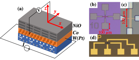
Two HM/FM/AFM multilayer systems consisting of two different heavy metals: W and Pt were deposited. As shown schematically in Fig. 1(a) the bottom-up heterostructure is sequenced as: Si//W(Pt)/Co/NiO. Heavy-metal layer was deposited in wedge shaped form with thickness varied from 0 to 10 nm along 20 mm long sample edge (x coordinate). The resulting thickness gradient was achieved by controlled movement of a shutter. The thicknesses of the two other layers namely Co and NiO were 0.7 nm and 7 nm, respectively. We also deposited Pt(4)/Co(1)/MgO system (thicknesses in nm) as a reference sample for further analysis. All metallic layers were deposited by magnetron sputtering at room temperature.
In the case of W sputtering, low DC power of 4 W and 6 cm target-sample distance were used, which resulted in a deposition rate of 0.01 nm/s. Such conditions are essential for the growth of W layer in the cubic phase. The Pt and Co were deposited with DC power of 8 and 15 W, respectively.
The stoichiometric NiO layer deposited on the top of Co layer was prepared from NiO target using a pulsed laser deposition technique (PLD). The process was performed in a controlled oxygen atmosphere under partial pressure mbar in a separate UHV chamber and samples were transferred between chambers without breaking UHV conditions. Systematic studies of the perpendicular exchange bias effect in Au/Co/NiO/Au system by magnetooptical Kerr rotation, published in the work [34], have shown that Co layer is oxidized due to deposition of NiO in an oxygen-rich atmosphere. Our X-ray absorption spectroscopy studies (for details see Supplemental Materials [39]) also confirm surface oxidation Co layer to stoichiometric CoO. The oxidation process effectively reduces the ferromagnetic thickness of Co which leads to an increase in the surface anisotropy finally revealing in strong PMA of Co. Moreover, interlayer exchange bias coupling appeared when perpendicular magnetic field of 1.1 kOe was applied during deposition.
Thicknesses of all layers were determined from the deposition growth rate of particular materials calibrated using x-ray reflectivity measurements. Next, all as-deposited samples were characterized before patterning by X-ray diffraction (XRD) and grazing incidence diffraction (GIXD) (for details see Supplemental Materials [39]). All systems were also examined by the polar Kerr magnetometer (p-MOKE) to determine the range of HM thicknesses for which PMA occurs. Square-shape hysteresis loops were observed, which indicate the presence of PMA in both systems for Pt layer thickness between 1 and 9 nm and for W layer thickness between 3.5 and 8 nm, which was next confirmed by anomalous Hall effect (AHE) measurements (see in Supplemental Materials [39]).
After basic characterization of continuous samples, both heterostructures were patterned using optical direct imaging lithography (DLP) and ion etching to create a matrix of Hall-bar devices, with different for subsequent electrical measurements (Fig. 1(b-d)). The sizes of prepared structures were 100 10 for magnetoresistance and AHE measurements and 30 30 for current-induced magnetization switching experiments. Al(20)/Au(30) electrical leads of 100 100 were deposited in a second lithography step followed by the lift-off process. Specific locations of pads near the Hall-bars were designed for measurement in custom-made rotating probe station allowing 2- or 4-points measurement of electrical transport properties in the presence of the magnetic field applied at arbitrary azimuthal and polar angle with respect to the Hall-bar axis.
The resistance of each Hall-bar was measured using a four-point method [40] and resistivities of Pt and W layers were determined using a parallel resistors model and the method described by Kawaguchi et al. [41]. The Pt and W resistivities analysis yielded 30 [41, 42, 14, 43] and 174 [44, 45, 46, 43], respectively. Depending on HM underlayer Co resistivity was 28 when deposited on Pt [14] and 58 on W. The details of the resistivity measurements are presented in Supplemental Materials [39].
III Critical current model
In order to determine the influence of exchange bias on threshold current in our system we follow the analysis for spin Hall threshold currents first derived by Lee et al. [47, 48].
We start with Landau-Lifshitz-Gilbert (LLG) equation for macrospin magnetization ,
| (1) |
where is Gilbert damping constant.
The general torque exerted on magnetization assumes the following form
| (2) |
where is the gyromagnetic constant, and the first term comes from the effective field, ,
where free energy of the FM has the following form
| (3) |
with being the field of effective perpendicular magnetic anisotropy, field of effective in-plane anisotropy, the magnetic field along , and the in-plane exchange bias.
The second torque term in Eq. (2) comes from damping-like field,
| (4) |
where is reduced Planck’s constant, is the elementary charge, is magnetization, is thickness of ferromagnetic layer, the spin Hall angle, the current density flowing through HM, and is the unitless real part of spin-mixing conductivity, with , , and the HM’s spin diffusion length, resistivity, and thickness, respectively. The damping-like field is induced by -polarized spin accumulation due to spin Hall effect in HM.
Stationary solution of the LLG equation (1) leads to the torque equilibrium condition, . For strong magnetic field applied along we assume which leads to the following condition for damping-like field
| (5) |
By analyzing stability of the above equation we obtain simplified relation for critical damping-like field
| (6) |
Inserting into the above equation explicit formula for damping like field, Eq. (4), we obtain for critical current density the following expression
| (7) |
Assuming perfect HM/FM interface, i.e. , and assuming leads to the simplified expression,
| (8) |
which is used later on to fit the experimental data. Note, that our model does not take into account switching mechanism due to creation and motion of domain walls, which has been observed in Pt/Co system [49] and results in smaller switching current density than the one estimated by the above model. Our estimate can, however, be treated as the upper limit.
IV Results and discussion
IV.1 SOT Current Switching
Anomalous Hall effect was used to determine the current-driven magnetization switching between high and low stable resistance states. The measurement setup is shown in Fig. 1(a). Initially, the sample has been magnetized by external magnetic field applied along z direction to the state corresponding to low resistance of the AHE loop.
Then, a sequence of current pulses with 10 ms duration and 20 ms intervals in the x direction was applied to drive the magnetization switching. The current was swept from negative to positive and back to negative and simultaneously transversal voltage was measured in presence of in-plane magnetic field, collinear with the current direction (. The value of was changed sequentially after each switching loop.
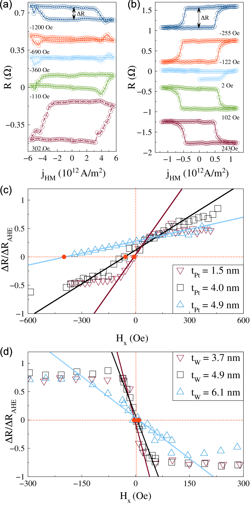
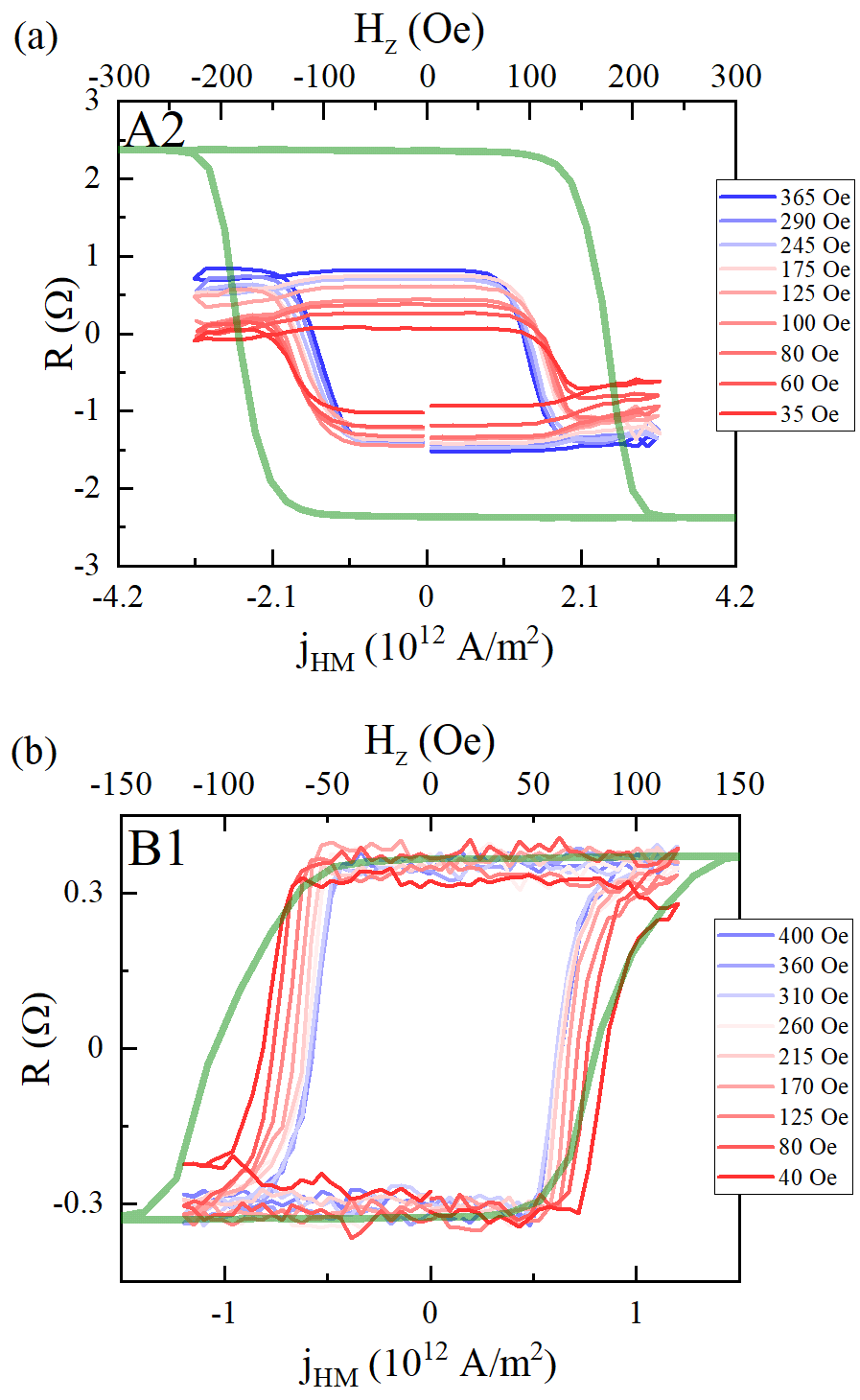
As a result, we obtained the current switching loops for Pt- and W-based Hall-bar devices (Fig. 2(a),(b)). Opposite loops polarities result that Pt has a positive spin Hall angle and W a negative one.
By analyzing the difference between high and low AHE resistance from AHE loop for different thickness of Pt and W-based devices was determined. Next, the current switching loop opening was measured, for each value of applied magnetic field , which shows closing loop with decreasing (Fig. 2(a),(b)). The ratio as a function of which is a measure of the effectiveness of current induced magnetization switching for Pt and W-devices is shown in Fig. 2(c),(d). Obtained dependence is approximately linear for small positive and negative . As can be seen, does not reach , even when large magnetic field is applied (See also Fig. S10 in Supplemental Materials [39]).
The intersection of linear function with zero , corresponding to the magnetic field for which the loop is closed, can be identified as the value of which compensates the in-plane component of exchange bias field () and allows to indirectly determine the value of , because the mentioned in-plane compensation field has the same value, but the opposite sign.
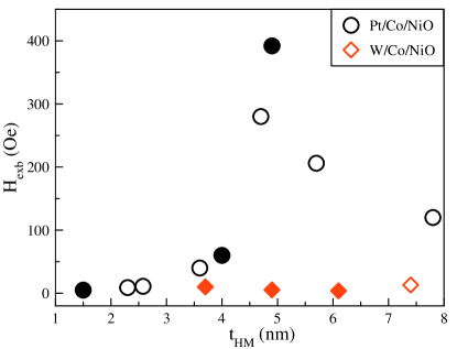
The intersection points for Pt-based system depend on Pt layer thickness, reaching maximal compensation field magnitude for =4.9 nm, while in W-based structure intersection occurs roughly at zero field in a wide range of W layer thicknesses as shown in Fig. 3. In high fields the saturates reaching for W-devices about (Fig. 2(d)), while for Pt-devices it changes with increasing Pt thickness from about to (Fig. 2(c) and Fig. S10(a) in Supplemental Materials [39]). The perpendicular exchange bias field (), determined by AHE hysteresis is highest for about 5 nm of HM thickness in both systems, but in W-based system is two times smaller than in Pt-based system (see Fig. S7 in Supplemental Materials [39]).
Because in as-deposited W/Co/NiO heterostructure the magnitude of is negligible, field-free SOT magnetization switching is not achieved. Therefore, to induce the in-plane component of exchange bias, the system was annealed at 100 (i.e. at a temperature slightly higher than blocking temperature of 373K but lower than Néel temperature of 525 K) for 15 min and then cooled to room temperature in the presence of external magnetic field of 4 kOe applied perpendicularly to the sample. Afterwards, the re-measured AHE loop for selected HM thickness indicates the presence of the PMA and in Co layer, manifested by rectangular shape shifted of -67 Oe (see Fig. S6(b) in Supplemental Materials [39]). In the next step the current switching experiments were repeated and results were analyzed as described above. Finally, = -148 Oe was obtained from measurements (see Fig. S10(b) in Supplemental Materials [39]). For further analysis and fitting our threshold current model in exchange-biased system, three as-deposited Pt/Co/NiO Hall-bar devices of 1.5, 4.0 and 4.9 nm Pt thicknesses were selected and identified as A2, A3 and A4, respectively. We selected also three as-deposited W/Co/NiO Hall-bars of 3.7, 4.9 and 6.1 nm W thicknesses which were marked as B1, B2 and B3, respectively, and chose annealed W(4.3)/Co/NiO device (C1). We also fitted our model to reference sample (labeled A1) which was used to verify the model, as indicated earlier.
| Pt/Co/MgO | |||||
| Sample | (nm) | (Oe) | —FIT (Oe) | —FIT (%) | (T) |
| A1 | 4.0 | 0 | 2508 80 | 13.5 1 | 0.5 |
| Pt/Co/NiO | |||||
| Sample | (nm) | (Oe) | —FIT (Oe) | —FIT (%) | (T) |
| A2 | 1.5 | 6 1 | 2141 10 | 4.1 0.8 | 0.5 |
| A3 | 4.0 | 176 3 | 4130 10 | 5.2 1.2 | 0.5 |
| A4 | 4.9 | 522 14 | 4638 10 | 5.8 1.3 | 0.5 |
| W/Co/NiO | |||||
| Sample | (nm) | (Oe) | —FIT (Oe) | —FIT (%) | (T) |
| B1 | 3.7 | 0 | 1132 20 | -5.7 1.1 | 0.5 |
| B2 | 4.9 | 30 15 | 1031 10 | -7.5 1.5 | 0.5 |
| B3 | 6.1 | 7 1 | 1035 11 | -9.3 1.8 | 0.5 |
| C1 | 4.3 | -158 29 | 2584 2 | -44.0 5 | 0.5 |
IV.2 In-plane exchange bias
In order to confirm the above-discussed , resistance along the Hall-bar () was measured with external magnetic field being swept along the direction and modeled it with the equation:
| (9) |
where is magnetization-independent resistance, and denotes changes due to anisotropic magnetoresistance effect. Considering equilibrium condition of energy density (Eq.3) with respect to angle longitudinal resistance was reformulated to:
| (10) |
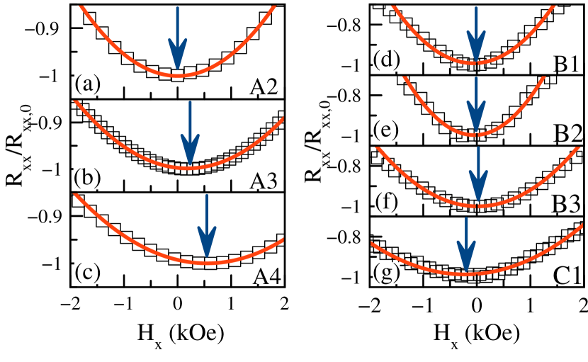
Measured for A2-A4, B1-B3 and C1 samples are shown in Fig. 4. A parabolic function has been fitted to the data points and minima of the functions are indicated with arrows. According to the Eq. (10), the minima can be identified as field, like these discussed in previous section. The resulting values for A2, A3 and A4 samples of about 6 Oe, 176 Oe and 522 Oe (Fig. 4(d)-(f)), respectively, are consistent with the ones obtained in opening loop of the current switching experiment described in Sec. IV A. As-deposited B-series Hall-bars still exhibit negligible loop shifts (Fig. 4(d)-(f)). The only exception is the annealed C1 element for which the value is -158 Oe (Fig. 4(g)). values obtained from magnetoresistance (MR) measurements are in general less noisy and are used for further analysis.
IV.3 Fitting procedure
For the analysis of the SOT-induced magnetization switching, we used AHE resistance hysteresis loops vs. applied current densities in HM layer () measured in a different external magnetic field - examples are depicted in Fig. 5.
First, using a derivative of , the threshold switching current () was calculated separately for each . As a result, linear dependencies of vs. are obtained for selected Pt and W thicknesses. Nevertheless, a large number of free parameters in the model equation (Eq. (8)) may cause large uncertainties in the determined values. For this purpose, the first part of Eq. (8) was replaced by a single parameter which was fixed and calculated as the linear slope coefficient determined by numerical differentiation of dependence. Therefore, Eq. (8) can be rewritten to form:
| (11) |
where: is fixed parameter obtained from differing dependence data points.
This ensures, that the only free fit parameter has remained . As mentioned earlier, has been fixed parameter achieved from the MR measurements.
Initially, the model was verified on the A1 reference sample, which is characterized by zero . In this particular case, both and parameters have been set as free to check validity of parameters received from fitting. As expected, = 0 and = 2508 Oe were obtained with a very good compliance level of = 0.93.
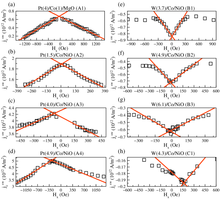
Next, a simplified model equation (Eq. (11)) was fitted to all selected Pt/Co/NiO and W/Co/NiO. As indicated, parameter was fixed and set accordingly with Tab.1. Fitting results are depicted in Fig. 6 where the solid lines correspond to the model equation, respectively for all investigated devices. As shown, the model proved good correlation to the data points. All of the coefficients were above 0.90, ensuring low uncertainty level. For higher there are deviations from linear dependence in both systems.
In case of W-devices, the deviations appear at lower field than in Pt. This can be explained by lower (see Tab. 1) for as-deposited W/Co/NiO than Pt/Co/NiO systems. Devices of A-series were characterized by increase and with increasing Pt thickness (Fig. 6(b)-(d)). Additionally, annealing of the B-series devices resulted in doubling value by increasing .
Finally, we calculated the effective spin Hall angles () in HM layer. For calculations we used the saturation of magnetization () equal to 0.5 T in both systems, obtained from VSM measurements (see Fig. S11 in Supplemental Materials [39]). We also assumed an infinite value of mixing conduction (), which is mostly valid for metallic interfaces [50].
Adopted assumptions allowed us to calculate the effective spin Hall angle from the following formula:
| (12) |
Obtained values of are listed in the Tab. 1 and agree with the ones found in the literature [14, 43, 51, 52, 42, 53, 54, 45, 55, 56, 57, 58, 59]. in as-deposited B-devices are slightly higher than values calculated for A-devices systems, which combined with significantly lower result in approximately one order of magnitude smaller critical switching current densities in this system. It is also worth noting that annealing of the W-based system, apart from induce also enhance to -44 % [58, 56, 45, 57] and the reduce of by the order of magnitude (Fig. 6(h)). In order to confirm high value of , a current switching experiment was performed on another annealed sample from the same series. A similar was obtained (see Fig. S9 in Supplemental materials [39]). We attribute a high value of the effective spin Hall angle of W similarly as in the works [43, 45, 58, 57], to the highly resistive -W phase. For example -30% at RT and over -50% at 50K in [56], while in [58] it is approximately -44%. Recently, Oliver L. W. McHugh et al. [59] showed, from first-principles calculations, that interstitials dopants of O and N help to stabilize -W grains during film deposition and this process leads to high spin Hall angles.
IV.4 Training effect
The training effect in both systems was also investigated for verification of thermal stability of the examined heterostructures. In order to do this 10 times longer pulses than in previous experiments described in Sec. IV A were used. For this purpose, a multiple current switching in a fixed external field was performed by 100 ms current pulses with 200 ms interval between them. The magnitude of the external field has been chosen to obtain an unambiguous magnetization switching. A series of current switching loops depicted in Fig. 7(a),(b) were obtained. Next, loops opening and critical current densities were determined as a function of loop numbers. The results are presented in Fig. 7(c),(d).
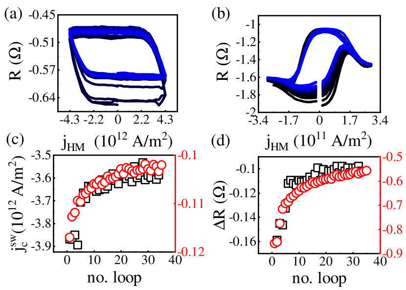
In both systems, and decrease with increasing number of magnetization switches and their dependence on loop number is similar. During the first few switching events, a significant reduction in both the and are observed. These phenomena can be explained by the progressively increasing temperature in both systems due to Joule heating [29] and training effect [28, 60, 61] witnessed also during magnetic field switching [62, 63, 28]. It is worth mentioning that Joule’s heating effect leads to the reduction of the switching current and anisotropy. Saturation of the dependence is caused by achieving a balance between the generated and emitted heating. This saturation occurs for smaller repetition number in the system with Pt (after about 20 switches) in contrast to W-based system in which it is not reached even after 35 switches.
Furthermore, for the Pt-based system we investigated how the number of switches affects . For this purpose, we measured longitudinal magnetoresistance signal, , as in Sec.IV B, before current switching experiment, and we found that was 302 Oe (Fig. 8(a)).
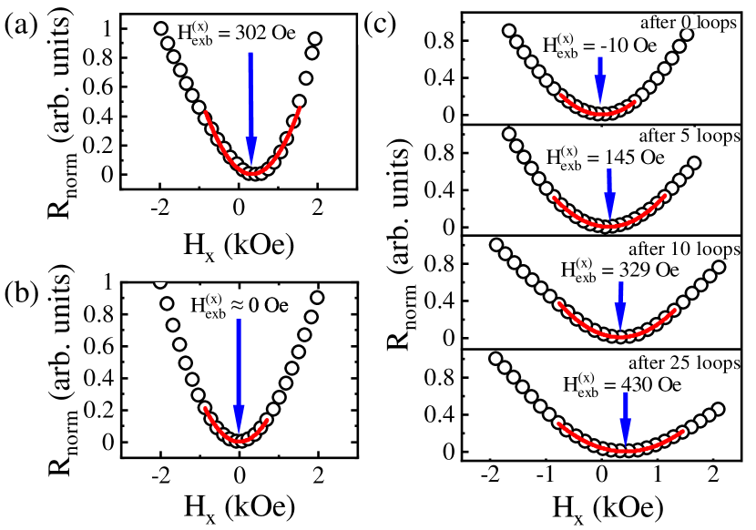
First, the sample was switched several times in zero external magnetic field. It was found that decreases to 0 Oe (Fig. 8(b)). This proves that thermal energy generated during the pulses leads to degradation of the component. The same reduction effect at switching without external magnetic field was noticed by Razavi et al. [29]. Then, by applying an in-plane field of -200 Oe, the multiple switching events were repeated. It turns out, that as the number of switching cycles increases, the rises up to 430 Oe after 25 switching loops as depicted in Fig. 8(c).
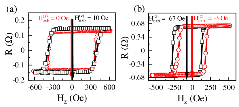
Finally, the AHE loop shapes and the in both systems were analyzed by comparing the loops before and after the current switching experiments. No significant degradation of PMA was found, however was reduced in both cases, as shown in Fig. 9, to 0 Oe and -3 Oe, respectively for Pt and W-based devices. We conclude that during the switching events, a significant Joule heating is generated, which may lead to the temperature increase above the Néel temperature. If the in-plane magnetic field is applied, an increase of in-plane exchange bias is accompanied by decrease of the perpendicular exchange bias component.
V Summary
In summary, the SOT-induced magnetization switching of (Pt,W)/Co/NiO with perpendicularly magnetized Co layer and varying HM thickness was examined. Both the in-plane and perpendicular exchange-bias were determined with current-driven switching, magnetoresistance and AHE methods. We demonstrate in both Pt/Co/NiO and W/Co/NiO systems the deterministic Co magnetization switching without external magnetic field which was replaced by in-plane exchange bias field. For several selected Hall-bar devices in both systems, threshold current densities were analyzed based on our theoretical model allowing us to estimate effective parameters and . Due to higher in W- than Pt-based system, approximately one order of magnitude smaller critical switching current density was found. The switching stability experiments confirm the ability to induce by thermal effects. Finally, we showed wide range of resistance changes in field-free magnetization switching in case of the (Pt, W)/Co/NiO system.
Acknowledgments
This work was supported by the National Science Centre Poland Grant No. UMO-2016/23/B/ST3/01430 (SPINORBITRONICS). WS acknowledges National Science Centre Grant Poland Grant No. 2015/17/D/ST3/00500. JK and WP acknowledge National Science Centre Poland Grant No. 2012/05/E/ST7/00240. PK and MK acknowledge the National Science Centre Poland Grant No. UMO-2015/18/E/ST3/00557. The authors would like to express their gratitude to dr. A. Kozioł-Rachwał and dr. M. Ślęzak for fruitful discussions and technical assistance in the XAS measurements. Nanofabrication was performed at the Academic Center for Materials and Nanotechnology of AGH University of Science and Technology. XAS experiment was performed at the SOLARIS National Synchrotron Radiation Centre.
References
- Brataas and Hals [2014] A. Brataas and K. M. D. Hals, Spin–orbit torques in action, Nature Nanotechnology 9, 86 (2014).
- Wang et al. [2017] T. Wang, J. Q. Xiao, and X. Fan, Spin–Orbit Torques in Metallic Magnetic Multilayers: Challenges and New Opportunities, SPIN 07, 1740013 (2017).
- Dieny et al. [2020] B. Dieny, I. L. Prejbeanu, K. Garello, P. Gambardella, P. Freitas, R. Lehndorff, W. Raberg, U. Ebels, S. O. Demokritov, J. Akerman, A. Deac, P. Pirro, C. Adelmann, A. Anane, A. V. Chumak, A. Hirohata, S. Mangin, S. O. Valenzuela, M. C. Onbaşlı, M. d’Aquino, G. Prenat, G. Finocchio, L. Lopez-Diaz, R. Chantrell, O. Chubykalo-Fesenko, and P. Bortolotti, Opportunities and challenges for spintronics in the microelectronics industry, Nature Electronics 3, 446 (2020).
- Garello et al. [2014] K. Garello, C. O. Avci, I. M. Miron, M. Baumgartner, A. Ghosh, S. Auffret, O. Boulle, G. Gaudin, and P. Gambardella, Ultrafast magnetization switching by spin-orbit torques, Applied Physics Letters 105, 212402 (2014).
- Fukami et al. [2016a] S. Fukami, T. Anekawa, C. Zhang, and H. Ohno, A spin–orbit torque switching scheme with collinear magnetic easy axis and current configuration, Nature Nanotechnology 11, 621 (2016a).
- Grimaldi et al. [2020] E. Grimaldi, V. Krizakova, G. Sala, F. Yasin, S. Couet, G. Sankar Kar, K. Garello, and P. Gambardella, Single-shot dynamics of spin–orbit torque and spin transfer torque switching in three-terminal magnetic tunnel junctions, Nature Nanotechnology 15, 111 (2020).
- Hirsch [1999] J. E. Hirsch, Spin Hall Effect, Physical Review Letters 83, 1834 (1999).
- Zhang [2000] S. Zhang, Spin Hall Effect in the Presence of Spin Diffusion, Physical Review Letters 85, 393 (2000).
- Sinova et al. [2015] J. Sinova, S. O. Valenzuela, J. Wunderlich, C. H. Back, and T. Jungwirth, Spin Hall effects, Rev. Mod. Phys. 87, 1213 (2015).
- Fan et al. [2014] Y. Fan, P. Upadhyaya, X. Kou, M. Lang, S. Takei, Z. Wang, J. Tang, L. He, L.-T. Chang, M. Montazeri, G. Yu, W. Jiang, T. Nie, R. N. Schwartz, Y. Tserkovnyak, and K. L. Wang, Magnetization switching through giant spin–orbit torque in a magnetically doped topological insulator heterostructure, Nature Materials 13, 699 (2014).
- Manchon et al. [2019] A. Manchon, J. Železný, I. Miron, T. Jungwirth, J. Sinova, A. Thiaville, K. Garello, and P. Gambardella, Current-induced spin-orbit torques in ferromagnetic and antiferromagnetic systems, Reviews of Modern Physics 91, 035004 (2019).
- Cai et al. [2017] K. Cai, M. Yang, H. Ju, S. Wang, Y. Ji, B. Li, K. W. Edmonds, Y. Sheng, B. Zhang, N. Zhang, S. Liu, H. Zheng, and K. Wang, Electric field control of deterministic current-induced magnetization switching in a hybrid ferromagnetic/ferroelectric structure, Nature Materials 16, 712 (2017).
- Lau et al. [2016] Y.-C. Lau, D. Betto, K. Rode, J. M. D. Coey, and P. Stamenov, Spin–orbit torque switching without an external field using interlayer exchange coupling, Nature Nanotechnology 11, 758 (2016).
- Łazarski et al. [2019] S. Łazarski, W. Skowroński, J. Kanak, L. Karwacki, S. Ziętek, K. Grochot, T. Stobiecki, and F. Stobiecki, Field-free spin-orbit-torque switching in // multilayer with mixed magnetic anisotropies, Phys. Rev. Applied 12, 014006 (2019).
- Baek et al. [2018] S.-h. C. Baek, V. P. Amin, Y.-W. Oh, G. Go, S.-J. Lee, G.-H. Lee, K.-J. Kim, M. D. Stiles, B.-G. Park, and K.-J. Lee, Spin currents and spin–orbit torques in ferromagnetic trilayers, Nature Materials 17, 509 (2018).
- Sheng et al. [2018] Y. Sheng, K. W. Edmonds, X. Ma, H. Zheng, and K. Wang, Adjustable Current-Induced Magnetization Switching Utilizing Interlayer Exchange Coupling, Advanced Electronic Materials 4, 1800224 (2018).
- Wang et al. [2018] X. Wang, C. Wan, W. Kong, X. Zhang, Y. Xing, C. Fang, B. Tao, W. Yang, L. Huang, H. Wu, M. Irfan, and X. Han, Field-free programmable spin logics via chirality-reversible spin–orbit torque switching, Advanced Materials 30, 1801318 (2018).
- Chuang et al. [2019] T. Chuang, C. Pai, and S. Huang, Cr -induced Perpendicular Magnetic Anisotropy and Field-Free Spin-Orbit-Torque Switching, Physical Review Applied 11, 061005 (2019).
- Cao et al. [2019] Y. Cao, A. Rushforth, Y. Sheng, H. Zheng, and K. Wang, Tuning a Binary Ferromagnet into a Multistate Synapse with Spin–Orbit-Torque-Induced Plasticity, Advanced Functional Materials 29, 1808104 (2019).
- Chen et al. [2019] S. Chen, J. Yu, Q. Xie, X. Zhang, W. Lin, L. Liu, J. Zhou, X. Shu, R. Guo, Z. Zhang, and J. Chen, Free Field Electric Switching of Perpendicularly Magnetized Thin Film by Spin Current Gradient, ACS Applied Materials & Interfaces 11, 30446 (2019).
- Safeer et al. [2016] C. K. Safeer, E. Jué, A. Lopez, L. Buda-Prejbeanu, S. Auffret, S. Pizzini, O. Boulle, I. M. Miron, and G. Gaudin, Spin–orbit torque magnetization switching controlled by geometry, Nature Nanotechnology 11, 143 (2016).
- You et al. [2015] L. You, O. Lee, D. Bhowmik, D. Labanowski, J. Hong, J. Bokor, and S. Salahuddin, Switching of perpendicularly polarized nanomagnets with spin orbit torque without an external magnetic field by engineering a tilted anisotropy, Proceedings of the National Academy of Sciences 112, 10310 (2015).
- Yu et al. [2014a] G. Yu, L.-T. Chang, M. Akyol, P. Upadhyaya, C. He, X. Li, K. L. Wong, P. K. Amiri, and K. L. Wang, Current-driven perpendicular magnetization switching in Ta/CoFeB/[TaOx or MgO/TaOx] films with lateral structural asymmetry, Applied Physics Letters 105, 102411 (2014a).
- Yu et al. [2014b] G. Yu, P. Upadhyaya, Y. Fan, J. G. Alzate, W. Jiang, K. L. Wong, S. Takei, S. A. Bender, L.-T. Chang, Y. Jiang, M. Lang, J. Tang, Y. Wang, Y. Tserkovnyak, P. K. Amiri, and K. L. Wang, Switching of perpendicular magnetization by spin–orbit torques in the absence of external magnetic fields, Nature Nanotechnology 9, 548 (2014b).
- Maat et al. [2001] S. Maat, K. Takano, S. S. P. Parkin, and E. E. Fullerton, Perpendicular Exchange Bias of multilayers, Physical Review Letters 87, 087202 (2001).
- Oh et al. [2016] Y.-W. Oh, S.-h. Chris Baek, Y. M. Kim, H. Y. Lee, K.-D. Lee, C.-G. Yang, E.-S. Park, K.-S. Lee, K.-W. Kim, G. Go, J.-R. Jeong, B.-C. Min, H.-W. Lee, K.-J. Lee, and B.-G. Park, Field-free switching of perpendicular magnetization through spin–orbit torque in antiferromagnet/ferromagnet/oxide structures, Nature Nanotechnology 11, 878 (2016).
- Fukami et al. [2016b] S. Fukami, C. Zhang, S. DuttaGupta, A. Kurenkov, and H. Ohno, Magnetization switching by spin–orbit torque in an antiferromagnet–ferromagnet bilayer system, Nature Materials 15, 535 (2016b).
- van den Brink et al. [2016] A. van den Brink, G. Vermijs, A. Solignac, J. Koo, J. Kohlhepp, H. Swagten, and B. Koopmans, Field-free magnetization reversal by spin-Hall effect and exchange bias, Nature communications 7, 10854 (2016).
- Razavi et al. [2017] S. A. Razavi, D. Wu, G. Yu, Y.-C. Lau, K. L. Wong, W. Zhu, C. He, Z. Zhang, J. M. D. Coey, P. Stamenov, P. Khalili Amiri, and K. L. Wang, Joule Heating Effect on Field-Free Magnetization Switching by Spin-Orbit Torque in Exchange-Biased Systems, Phys. Rev. Applied 7, 024023 (2017).
- Manchon [2017] A. Manchon, Spin diffusion and torques in disordered antiferromagnets, Journal of Physics: Condensed Matter 29, 104002 (2017).
- Kuświk et al. [2018] P. Kuświk, M. Matczak, M. Kowacz, K. Szuba-Jabłoński, N. Michalak, B. Szymański, A. Ehresmann, and F. Stobiecki, Asymmetric domain wall propagation caused by interfacial Dzyaloshinskii-Moriya interaction in exchange biased Au/Co/NiO layered system, Phys. Rev. B 97, 024404 (2018).
- Kuświk et al. [2018] P. Kuświk, A. Gaul, M. Urbaniak, M. Schmidt, J. Aleksiejew, A. Ehresmann, and F. Stobiecki, Tailoring Perpendicular Exchange Bias Coupling in Au/Co/NiO Systems by Ion Bombardment, Nanomaterials 8, 813 (2018).
- Mazalski et al. [2020] P. Mazalski, B. Anastaziak, P. Kuświk, Z. Kurant, I. Sveklo, and A. Maziewski, Demagnetization of an ultrathin Co/NiO bilayer with creation of submicrometer domains controlled by temperature-induced changes of magnetic anisotropy, Journal of Magnetism and Magnetic Materials 508, 166871 (2020).
- Kuświk et al. [2016] P. Kuświk, B. Szymański, B. Anastaziak, M. Matczak, M. Urbaniak, A. Ehresmann, and F. Stobiecki, Enhancement of perpendicular magnetic anisotropy of Co layer in exchange-biased Au/Co/NiO/Au polycrystalline system, Journal of Applied Physics 119, 215307 (2016).
- Yang et al. [2011] H. Yang, S.-H. Yang, D.-C. Qi, A. Rusydi, H. Kawai, M. Saeys, T. Leo, D. J. Smith, and S. S. P. Parkin, Negative Tunneling Magnetoresistance by Canted Magnetization in MgO / NiO Tunnel Barriers, Physical Review Letters 106, 167201 (2011).
- Ono et al. [1996] K. Ono, H. Shimada, S.-i. Kobayashi, and Y. Ootuka, Magnetoresistance of Ni/NiO/Co Small Tunnel Junctions in Coulomb Blockade Regime, Journal of the Physical Society of Japan 65, 3449 (1996).
- Sokolov et al. [2003] A. Sokolov, I. F. Sabirianov, E. Y. Tsymbal, B. Doudin, X. Z. Li, and J. Redepenning, Resonant tunneling in magnetoresistive Ni/NiO/Co nanowire junctions, Journal of Applied Physics 93, 7029 (2003).
- Moriyama et al. [2015] T. Moriyama, S. Takei, M. Nagata, Y. Yoshimura, N. Matsuzaki, T. Terashima, Y. Tserkovnyak, and T. Ono, Anti-damping spin transfer torque through epitaxial nickel oxide, Applied Physics Letters 106, 162406 (2015).
- [39] Supplemental material at [url].
- Smits [1958] F. Smits, Measurement of sheet resistivities with the four-point probe, Bell System Technical Journal 34, 711 (1958).
- Kawaguchi et al. [2018] M. Kawaguchi, D. Towa, Y.-C. Lau, S. Takahashi, and M. Hayashi, Anomalous spin hall magnetoresistance in Pt/Co bilayers, Applied Physics Letters 112 (2018).
- Sagasta et al. [2016] E. Sagasta, Y. Omori, M. Isasa, M. Gradhand, L. E. Hueso, Y. Niimi, Y. Otani, and F. Casanova, Tuning the spin Hall effect of Pt from the moderately dirty to the superclean regime, Phys. Rev. B 94, 060412 (2016).
- Skowroński et al. [2019] W. Skowroński, L. Karwacki, S. Ziętek, J. Kanak, S. Łazarski, K. Grochot, T. Stobiecki, P. Kuświk, F. Stobiecki, and J. Barnaś, Determination of spin hall angle in heavy-metal/-based heterostructures with interfacial spin-orbit fields, Phys. Rev. Applied 11, 024039 (2019).
- Hao et al. [2015] Q. Hao, W. Chen, and G. Xiao, Beta () tungsten thin films: Structure, electron transport, and giant spin Hall effect, Applied Physics Letters 106, 182403 (2015).
- Hao and Xiao [2015] Q. Hao and G. Xiao, Giant spin hall effect and switching induced by spin-transfer torque in a structure with perpendicular magnetic anisotropy, Phys. Rev. Applied 3, 034009 (2015).
- Neumann et al. [2016] L. Neumann, D. Meier, J. Schmalhorst, K. Rott, G. Reiss, and M. Meinert, Temperature dependence of the spin hall angle and switching current in the system with perpendicular magnetic anisotropy, Applied Physics Letters 109, 142405 (2016).
- Lee et al. [2013] K.-S. Lee, S.-W. Lee, B.-C. Min, and K.-J. Lee, Threshold current for switching of a perpendicular magnetic layer induced by spin Hall effect, Appl. Phys. Lett. 102, 112410 (2013).
- Taniguchi [2019] T. Taniguchi, Theoretical condition for switching the magnetization in a perpendicularly magnetized ferromagnet via the spin Hall effect, Physical Review B 100, 174419 (2019).
- Baumgartner et al. [2017] M. Baumgartner, K. Garello, J. Mendil, C. O. Avci, E. Grimaldi, C. Murer, J. Feng, M. Gabureac, C. Stamm, Y. Acremann, S. Finizio, S. Wintz, J. Raabe, and P. Gambardella, Spatially and time-resolved magnetization dynamics driven by spin–orbit torques, Nature Nanotechnology 12, 980 (2017).
- Kim et al. [2016] J. Kim, P. Sheng, S. Takahashi, S. Mitani, and M. Hayashi, Spin Hall magnetoresistance in metallic bilayers, Phys. Rev. Lett. 116, 097201 (2016).
- Rojas-Sánchez et al. [2014] J.-C. Rojas-Sánchez, N. Reyren, P. Laczkowski, W. Savero, J.-P. Attané, C. Deranlot, M. Jamet, J.-M. George, L. Vila, and H. Jaffrès, Spin pumping and inverse spin hall effect in platinum: The essential role of spin-memory loss at metallic interfaces, Phys. Rev. Lett. 112, 106602 (2014).
- Pai et al. [2012] C. F. Pai, L. Liu, Y. Li, H. W. Tseng, D. C. Ralph, and R. A. Buhrman, Spin transfer torque devices utilizing the giant spin Hall effect of tungsten, Applied Physics Letters 101 (2012).
- Takeuchi et al. [2018] Y. Takeuchi, C. Zhang, A. Okada, H. Sato, S. Fukami, and H. Ohno, Spin-orbit torques in high-resistivity-, Applied Physics Letters 112, 192408 (2018).
- Cho et al. [2015] S. Cho, S.-h. C. Baek, K.-D. Lee, Y. Jo, and B.-G. Park, Large spin Hall magnetoresistance and its correlation to the spin-orbit torque in W/CoFeB/MgO structures, Scientific Reports 5, 14668 (2015).
- Zhang et al. [2016] C. Zhang, S. Fukami, K. Watanabe, A. Ohkawara, S. DuttaGupta, H. Sato, F. Matsukura, and H. Ohno, Critical role of w deposition condition on spin-orbit torque induced magnetization switching in nanoscale W/CoFeB/MgO, Applied Physics Letters 109, 192405 (2016).
- Skowroński et al. [2016] W. Skowroński, M. Cecot, J. Kanak, S. Ziętek, T. Stobiecki, L. Yao, S. van Dijken, T. Nozaki, K. Yakushiji, and S. Yuasa, Temperature dependence of spin-orbit torques in W/CoFeB bilayers, Applied Physics Letters 109, 062407 (2016).
- Chen et al. [2018] W. Chen, G. Xiao, Q. Zhang, and X. Zhang, Temperature study of the giant spin Hall effect in the bulk limit of -W, Physical Review B 98, 134411 (2018).
- Bansal et al. [2018] R. Bansal, G. Nirala, A. Kumar, S. Chaudhary, and P. K. Muduli, Large spin hall angle in -W thin films grown on CoFeB without oxygen plasma, SPIN (2018).
- McHugh et al. [2020] O. L. W. McHugh, W. F. Goh, M. Gradhand, and D. A. Stewart, Impact of impurities on the spin Hall conductivity in -W, Physical Review Materials 4, 094404 (2020).
- Zhang et al. [2001] K. Zhang, T. Zhao, and H. Fujiwara, Training effect of exchange biased iron–oxide/ferromagnet systems, Journal of Applied Physics 89, 6910 (2001).
- Brems et al. [2007] S. Brems, K. Temst, and C. Van Haesendonck, Origin of the training effect and asymmetry of the magnetization in polycrystalline exchange bias systems, Phys. Rev. Lett. 99, 067201 (2007).
- Binek [2004] C. Binek, Training of the exchange-bias effect: A simple analytic approach, Phys. Rev. B 70, 014421 (2004).
- Hochstrat et al. [2002] A. Hochstrat, C. Binek, and W. Kleemann, Training of the exchange-bias effect in nio-fe heterostructures, Phys. Rev. B 66, 092409 (2002).