Sensor-Based Control for Collaborative Robots: Fundamentals, Challenges and Opportunities
Abstract
The objective of this paper is to present a systematic review of existing sensor-based control methodologies for applications that involve direct interaction between humans and robots, in the form of either physical collaboration or safe coexistence. To this end, we first introduce the basic formulation of the sensor-servo problem, then present the most common approaches: vision-based, touch-based, audio-based, and distance-based control. Afterwards, we discuss and formalize the methods that integrate heterogeneous sensors at the control level. The surveyed body of literature is classified according to the type of sensor, to the way multiple measurements are combined, and to the target objectives and applications. Finally, we discuss open problems, potential applications, and future research directions.
Keywords: Robotics, human-robot collaboration, sensor-based control.
1 Introduction
Robot control is a mature field: one that is already being heavily commercialized in industry. However, the methods required to regulate interaction and collaboration between humans and robots have not been fully established yet. These issues are the subject of research in the fields of physical human-robot interaction (pHRI) [1] and collaborative robotics (CoBots) [2]. The authors of [3] present a paradigm that specifies the three nested layers of consistent behaviors that the robot must follow to achieve safe pHRI:
-
•
Safety is the first and most important feature in collaborative robots. Although there has been a recent push towards standardization of robot safety (e.g., the ISO 13482:2014 for robots and robotic devices [4]), we are still in the initial stages. Safety is generally addressed through collision avoidance (with both humans or obstacles [5]), a feature that requires high reactivity (high bandwidth) and robustness at both the perception and control layers.
-
•
Coexistence is the robot capability of sharing the workspace with humans. This includes applications involving a passive human (e.g., medical operations where the robot is intervening on the patients’ body [6]), as well as scenarios where robot and human work together on the same task, without contact or coordination.
-
•
Collaboration is the capability of performing robot tasks with direct human interaction and coordination. There are two modes for this: physical collaboration (with explicit and intentional contact between human and robot), and contactless collaboration (where the actions are guided by an exchange of information, e.g., in the form of body gestures, voice commands, or other modalities). Especially for the second mode, it is crucial to establish means for intuitive control by the human operators, which may be non-expert users. The robot should be proactive in realizing the requested tasks, and it should be capable of inferring the user’s intentions, to interact more naturally from the human viewpoint.
All three layers are hampered by the unpredictability of human actions, which vary according to situations and individuals, complicating modeling [7], and use of classic control.
In the robotics literature, two major approaches for task execution have emerged: path/motion planning [8] and sensor-based control [9]. The planning methods rely on a priori knowledge of the future robot and environment states over a time window. Although they have proved their efficiency in well-structured applications, these methods are hardly applicable to human-robot collaboration, because of the unpredictable and dynamic nature of humans. It is in the authors’ view that sensor-based control is more efficient and flexible for pHRI, since it closes the perception-to-action loop at a lower level than path/motion planning. Note also that sensor-based control strategies strongly resemble the processes of our central nervous system [10], and can trace their origins back to the servomechanism problem [11]. The most known example is image-based visual servoing [9] which relies directly on visual feedback to control robot motion, without requiring a cognitive layer nor a precise model of the environment.
The aim of this article is to survey the current state of art in sensor-based control, as a means to facilitate the interaction between robots, humans, and surrounding environments. Although we acknowledge the need for other techniques within a complete human-robot collaboration framework (e.g., path planning as mentioned, machine learning, etc.), here we review and classify the works which exploit sensory feedback to directly command the robot motion.
The timing and relevance of this survey is twofold. On one hand, while there have been previous reviews on topics such as (general) human-robot collaboration [12, 13] and human-robot safety [14], there is no specific review on the use of sensor-based control for human-robot collaborative tasks. On the other hand, we introduce a unifying paradigm for designing controllers with four sensing modalities. This feature gives our survey a valuable tutorial-like nature.
The rest of this manuscript is organized as follows: Section 2 presents the basic formulation of the sensor-based control problem; Section 3 describes the common approaches that integrate multiple sensors at the control level. Section 4 provides several classifications of the reviewed works. Section 5 presents insights and discusses open problems and areas of opportunity. Conclusions are given in Section 6.
2 Sensing Modalities for Control
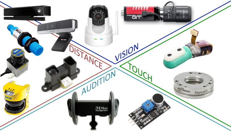
Recent developments on bio-inspired measurement technologies have made sensors affordable and lightweight, easing their use on robots. These sensors include RGB-D cameras, tactile skins, force/moment transducers, etcetera (see Fig. 1). The works reviewed here rely on different combinations of sensing modalities, depending on the task at stake. We consider the following four robot senses:
-
•
Vision. This includes methods for processing and understanding images, to produce numeric or symbolic information reproducing human sight. Although image processing is complex and computationally expensive, the richness of this sense is unique. Robotic vision is fundamental for understanding the environment and human intention, so as to react accordingly.
-
•
Touch. In this review, touch includes both proprioceptive force and tact, with the latter involving direct physical contact with an external object. Proprioceptive force is analogous to the sense of muscle force [15]. The robot can measure it either from the joint position errors or via torque sensors embedded in the joints; it can then use both methods to infer and adapt to human intentions, by relying on force control [16, 17, 18, 19]. Human tact (somatosensation), on the other hand, results from activation of neural receptors, mostly in the skin. These have inspired the design of artificial tactile skins [20, 21], thoroughly used for human-robot collaboration.
-
•
Audition. In humans, localization of sound is performed by using binaural audition (i.e., two ears). They exploit auditory cues in the form of level/time/phase differences between left and right ears to determine the source’s horizontal position and its elevation [22]. Microphones artificially emulate this sense, and allow robots to “blindly” locate sound sources. Although robotic hearing typically uses two microphones mounted on a motorized head, other non-biological configurations exist, e.g. a head instrumented with a single microphone or an array of several omni-directional microphones [23].
-
•
Distance. This is the only sense among the four that humans cannot directly measure. Yet, numerous examples exist in the mammal kingdom (e.g., bats and whales), in the form of echolocation. Robots measure distance with optical (e.g., infrared or lidar), ultrasonic, or capacitive [24] sensors. The relevance of this particular “sense” in human-robot collaboration is motivated by the direct relationship existing between the distance from obstacles (here, the human) and safety.
Roboticists have designed other bio-inspired sensors, to smell (see [25] for a comprehensive survey and [26, 27, 28] for 3D tracking applications) and taste [29, 30, 31]. However, in our opinion, artificial smell and taste are not yet mature enough for human-robot collaboration. Most of the current work on these senses is for localization/identification of hazardous gases/substances. For these reasons, this review will focus only on the four senses mentioned above, namely vision, touch, audition and distance.
3 Sensor-Based Control
3.1 Bio-Inspired Strategy
Currently, one of the most disruptive theories in cognitive science — the embodied cognition theory — states that sophisticated bodily behaviors (e.g. choreographed limb motions) result from perceptually-guided actions of the body and of its interaction with the environment [32]. This revolutionary idea (referred by Shapiro as the “replacement hypothesis” [33]) challenges traditional cognitive science, by proposing the total replacement of complex symbolic task representations with simpler perception-to-action regulatory models. A classic example of this theory is the baseball outfielder problem. For traditional cognitive science, it is solved by computing a physics-based simulation of the flying ball to predict its trajectory and landing point [34]. Instead, the embodied cognition counterpart formulates the solution as the explicit control of the optical ball movements (as perceived by the outfielder) by running lateral paths that maintain a linear optical trajectory, to anticipate the ball trajectory and perform a successful catch [35]. From the perspective of robotics, the latter approach is interesting as it clearly models the — apparently complex — motion task as a simple feedback control problem, which can be solved with sensor-based strategies, and without simulations or symbolic task representations. The following section reviews the basic formulation of sensor-based feedback control, since it is the most used in the papers that we reviewed.
3.2 Formulation of Sensor-Based Control
Sensor-based control aims at deriving the robot control input (operational space velocity, joint velocity, displacement, etc.) that minimizes a trajectory error , which can be estimated by sensors and depends on . A general way of formulating this controller (accounting for actuation redundancy , sensing redundancy , and task constraints) is as the quadratic minimization problem:
| (1) | ||||
| subject to task constraints. |
This formulation encompasses the classic inverse kinematics problem [36] of controlling the robot joint velocities (), so that the end-effector operational space position converges to a desired value . By defining the desired end-effector rate as , for , and setting for as the Jacobian matrix, it is easy to show that the solution to (1) (in the absence of constraints) is , with the generalized inverse of . This leads to the set-point controller111Throughout the paper, is a positive tuning scalar that determines the convergence rate of task error to .:
| (2) |
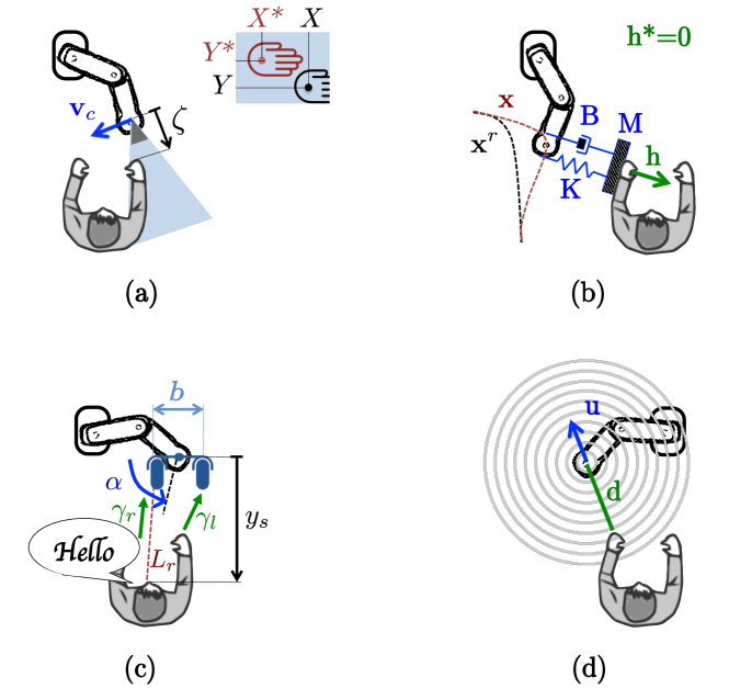
In the following sections, we show how each of the four senses (vision, touch, audition and distance) has been used for robot control, either with (1), or with similar techniques. Figure 2 shows relevant variables for the four cases. For simplicity, we assume there are no constraints in (1), although off-the-shelf quadratic programming solvers [37] could account for them.
3.3 Visual Servoing
3.3.1 Formulation
Visual servoing refers to the use of vision to control the robot motion [9]. The camera may be mounted on a moving part of the robot, or fixed in the workspace. These two configurations are referred to as “eye-in-hand” and “eye-to-hand” visual servoing, respectively. The error is defined with regards to some image features, here denoted by , to be regulated to a desired configuration ( is analogous to in the inverse kinematic formulation above). The visual error is:
| (3) |
Visual servoing schemes are called image-based if is defined in image space, and position-based if is defined in the 3D operational space. Here we only briefly recall the image-based approach (on its eye-in-hand modality), since the position-based one consists in projecting the task from the image to the operational space to obtain and then apply (2).
The simplest image-based controller uses , with and as the coordinates of an image pixel, to generate that drives to a reference (in Fig. 2a the centroid of the human hand). This is done by defining as:
| (4) |
If we use the camera’s 6D velocity as the control input , the image Jacobian matrix222Also known as interaction matrix in the visual servoing literature. relating and is:
| (5) |
where denotes the depth of the point with respect to the camera. In the absence of constraints, the solution of (1) is:
| (6) |
3.3.2 Application to Human-Robot Collaboration
Humans generally use vision to teach the robot relevant configurations for collaborative tasks. For example, [38] demonstrates an application where a human operator uses a QR code to specify the target poses for a 6 degrees-of-freedom (dof) robot arm. In [39] the user provides the target tasks via a tablet-like interface that shows the robot the desired reference view. The human can specify various motions such as point-to-point, line-to-line, etc., that are automatically performed via visual feedback. The authors of [40] present a grasping system for a tele-operated dual arm robot. The user specifies the object to be manipulated, and the robot completes the task using visual servoing.
Assistive robotics represents another very common application domain for visual servoing. The motion of robotic wheelchairs has been semi-automated at various degrees. For instance, [41] presents a corridor following method that exploits the projection of parallel lines. The user provides target directions with a haptic interface, and the robot corrects the trajectories with visual feedback. Other works focus on mobile manipulation. The authors of [42] develop a vision-based controller for a robotic arm mounted on a wheelchair: the user specifies the object to be grasped and retrieved by the robot. A similar approach is reported in [43], where, the desired poses are input with “clicks” on an screen interface.
3.4 Touch (or Force) Control
3.4.1 Formulation
Touch (or force) control requires the measurement of one or multiple (in the case of tactile skins) wrenches , which are (at most) composed of 3 translational forces, and 3 torques; is fed to the controller that moves the robot so that it exerts a desired interaction force with the human or environment. Force control strategies can be grouped into the following two classes [17]:
-
•
Direct control regulates the contact wrench to obtain a desired wrench . Specifying requires an explicit model of the task and environment. A widely adopted strategy is hybrid position/force control [18], which regulates the velocity and wrench along unconstrained and constrained task directions, respectively. Referring to (1), this is equivalent to setting
(7) with a binary diagonal selection matrix, and as the identity matrix. Applying a motion that nullifies in (7) guarantees that the components of (respectively ) specified via (respectively ) converge to (respectively ).
-
•
Indirect control (illustrated in Fig. 2b) does not require an explicit force feedback loop. To this category belong impedance control and its dual admittance control [16]. It consists in modelling the deviation of the contact point from a reference trajectory associated to the desired , via a virtual mechanical impedance with adjustable parameters (inertia , damping and stiffness ). Referring to (1), this is equivalent to setting:
(8) Here, represents the “deviated” contact point pose, with and as time derivatives. When , the displacement responds as a mass-spring-damping system under the action of an external force . In most cases, is defined for motion in free space (). The general formulation in (1) and (8) can account for both impedance control ( is measured and ) and admittance control ( measured and ).
3.4.2 Application to Human-Robot Collaboration
The authors of [45] use direct force control for collaborative human-robot laparoscopic surgery. They control the instruments with a hybrid position/force approach. In [46], a robot regulates the applied forces onto a beating human heart. Since the end-effector’s 3 linear dof are fully-constrained, position control cannot be performed: in (7).
A drawback of direct control is that it can realize only the tasks which can be described via constraint surfaces. If their location is unknown and/or the contact geometry is complex—as often in human-robot collaboration—indirect control is more suited since: i) it allows to define a priori how the robot should react to unknown external force disturbances, ii) it can use a reference trajectory output by another sensor (e.g., vision). In the next paragraph, we review indirect force control methods.
By sensing force, the robot can infer the motion commands (e.g., pushing, pulling) from the human user. For example, Maeda et al. [47] use force sensing and human motion estimation (based on minimum jerk) within an indirect (admittance) control framework for cooperative manipulation. In [48, 49], an assistant robot suppresses the involuntary vibrations of a human, who controls welding direction and speed. By exploiting kinematic redundancy, [50] also addresses manually guided robot operation. The papers [51, 52] present admittance controllers for two-arm robots moving a table in collaboration with a human. In [53], a human can control a medical robot arm, with an admittance controller. Robot Tele-operation is another common human-robot collaboration application where force feedback plays a crucial role; [54] is a comprehensive review on the topic.
All these works rely on local force/moment measures. To date, tactile sensors and skins (measuring the wrench along the robot body, see [55] for a review) have been used for object exploration [56] or recognition [57], but not for control as expressed in (1). One reason is that they are at a preliminary design stage, which still requires complex calibration [58, 59] that constitutes a research topic per se. An exception is [60], which uses tactile measures within (1). Similarly, in [61], tactile sensing regulates interaction with the environment. Yet, neither of these works considers pHRI. In our opinion, there is huge potential in the use of skins and tactile displays for human-robot collaboration.
3.5 Audio-Based control
3.5.1 Formulation
The purpose of audio-based control is to locate the sound source, and move the robot towards it. For simplicity, we present the two-dimensional binaural (i.e., with two microphones) configuration in Fig. 2c, with the angular velocity of the microphone rig as control input: . We hereby review the two most popular methods for defining error in (1): Interaural Time Difference (ITD) and Interaural Level Difference (ILD)333Or its frequency counterpart: Interaural Phase Difference (IPD).. The following is based on [62]:
-
•
ITD-based aural servoing uses the difference between the arrival times of the sound on each microphone; must be regulated to a desired . The controller can be represented with (1), by setting , with the desired rate (to obtain set-point regulation to ). Feature can be derived in real-time by using standard cross-correlation of the signals [63]. Under a far field assumption:
(9) with the sound celerity and the microphones baseline. From (9), the scalar ITD Jacobian is: . The motion that minimizes is:
(10) which is locally defined for , to ensure that .
-
•
ILD-based aural servoing uses , the difference in intensity between the left and right signals. This can be obtained in a time window of size as , where the denote the signals’ sound energies and the are the intensities at iteration . To regulate to a desired , one can set with . Assuming spherical propagation and slowly varying signal:
(11) where is the sound source frontal coordinate in the moving auditory frame, and the distance between the right microphone and the source. From (11), the scalar ILD Jacobian is . The motion that minimizes is:
(12) where is defined for sources located in front of the rig. In contrast with ITD-servoing, here the source location (i.e., and ) must be known or estimated.
While the methods above only control the angular velocity of the rig (), Magassouba has extended both to also regulate the 2D translations of a mobile platform, (ITD in [64, 65] and ILD in [66]).
3.5.2 Application to Human-Robot Collaboration
Due to the nature of this sense, audio-based controllers are mostly used in contact-less applications, to enrich other senses (e.g., force, distance) with sound, or to design intuitive interfaces.
Audio-based control is currently (in our opinion) an underdeveloped research area with great potential for human-robot collaboration, e.g., for tracking a speaker. Besides the cited works [62, 64, 65, 66], that closely follow the framework of Sec. 3, others formulate the problem differently. For example, the authors of [67, 68] propose a linear model to describe the relation between the pan motion of a robot head and the difference of intensity between its two microphones. The resulting controllers are much simpler than (10) and (12). Yet, their operating range is smaller, making them less robust than their – more analytical – counterparts.
3.6 Distance-Based control
3.6.1 Formulation
The simplest (and most popular) distance-based controller is the artificial potential fields method [5]. Despite being prone to local minima, it has been thoroughly deployed both on manipulators and on autonomous vehicles for obstacle avoidance. Besides, it is acceptable that a collaborative robot stops (e.g., because of local minima) as long as it avoids the human user. The potential fields method consists in modeling each obstacle as a source of repulsive forces, related to the robot distance from the obstacle (see Fig. 2d). All the forces are summed up resulting in a velocity in the most promising direction. Given , the position of the nearest obstacle in the robot frame, the original version [5] consists in applying operational space velocity
| (13) |
Here is the (arbitrarily tuned) minimal distance required for activating the controller. Since the quadratic denominator in (13) yields abrupt accelerations, more recent versions adopt a linear behavior. Referring to (1), this can be obtained by setting with as reference velocity:
| (14) |
By defining as control input , the solution to (1) is:
| (15) |
3.6.2 Application to Human-Robot Collaboration
Many works use this (or similar) distance-based methods for pHRI. To avoid human-robot collisions, the authors of [69] apply (15), by estimating between human head and robot with vision. Recently, these approaches have been boosted by the advent of 3D vision sensors (e.g. the Microsoft Kinect and Intel RealSense), which can provide both vision and distance control. The authors of [70] design a Kinect-based distance controller (again, for human collision avoidance) with an expression similar to (15), but smoothed by a sigmoid.
Proximity servoing is a similar technique, which regulates—via capacitive sensors—the distance between the robot surface and the human. In [71], these sensors modify the position and velocity of a robot arm when a human approaches it, to avoid collisions. The authors of [72, 73, 74] have developed a new capacitive skin for a dual-arm robot. They design a collision avoidance method based on an admittance model similar to (8), which relies on the joint torques (measured by the skin) to control the robot motion.
4 Integration of Multiple Sensors
In Sect. 3, we presented the most common sensor-based methods used for collaborative robots. Just like natural senses, artificial senses provide complementary information about the environment. Hence, to effectively perform a task, the robot should measure (and use for control) multiple feedback modalities. In this section, we review various methods for integrating multiple sensors in a unique controller.
Inspired by how humans merge their percepts [75], researchers have traditionally fused heterogeneous sensors to estimate the state of the environment. This can be done in the sensors’ Cartesian frames [76] by relying on an Extended Kalman Filter (EKF) [77]. Yet the sensors must be related to a single quantity, which is seldom the case when measuring different physical phenomena [78]. An alternative is to use the sensed feedback directly in (1). This idea, proposed for position-force control in [18] and extended to vision in [79], brings new challenges to the control design, e.g., sensor synchronization, task compatibility and task representation. For instance, the designer should take care when transforming D velocities or wrenches to a unique frame. This requires (when mapping from frame to frame ) multiplication by
| (16) |
for a velocity, and by for a wrench. In (16), is the rotation matrix from to and the skew-symmetric matrix associated to translation .
According to [79], the three methods for combining sensors within a controller are:
-
•
Traded: the sensors control the robot one at a time. Predefined conditions on the task trigger the switches:
(17) - •
-
•
Hybrid: the sensors act simultaneously, but on different axes of a predefined Cartesian task-frame [80]. The directions are selected by binary diagonal matrices , with the dimension of the task space, and such that :
(19) To express all in the same task frame, one should apply and/or . Note the analogy between (19) and the hybrid position/force control framework (7).
We will use this classification to characterize the works reviewed in the rest of this Section.
4.1 Traded Control
The paper [83] presents a human-robot manufacturing cell for collaborative assembly of car joints. The approach (traded vision/touch) can manage physical contact between robot and human, and between robot and environment, via admittance control (8). Vision takes over in dangerous situations to trigger emergency stops. The switching condition is determined by the position of the human wrt the robot.
In [84, 85], a traded vision/audio controller enables a mobile robot to exploit sound source localization for visual control. The robot head automatically rotates towards the estimated direction of the human speaker, and then visually tracks him/her. The switching condition is that the sound source is visible. The audio-based task is equivalent to regulating to or to , as discussed in Sect. 3.5. Paper [86] presents another traded vision/audio controller for the iCub robot head to localize a human speaker. This method constructs audio-motor maps based and integrates visual feedback to update the map. Again, the switching condition is that the speaker’s face is visible. In [87], another traded vision/audio controller is deployed on a mobile robot, to drive it towards an unknown sound source; the switching condition is defined by a threshold on the frontal localization error.
The authors of [88] present a mobile assistant for people with walking impairments. The robot is equipped with: two wrench sensors to measure physical interaction with the human, an array of microphones for audio commands, laser sensors for detecting obstacles, and an RGB-D camera for estimating the users’ state. Its controller integrates audio, touch, vision and distance in a traded manner, with switching conditions determined by a knowledge-based layer.
The work [89] presents an object manipulation strategy, integrating distance (capacitive proximity sensors) and touch (tactile sensors). While the method does not explicitly consider humans, it may be applied for human-robot collaboration, since proximity sensors can detect humans if vision is occluded. The switching condition between the two modes is the contact with the object.
Another example of traded control—here, audio/distance—is [90], which presents a method for driving a mobile robot towards hidden sound sources, via an omnidirectional array of microphones. The controller switches to ultrasound-based obstacle avoidance in the presence of humans/objects. The detection of a nearby obstacle is the switching condition.
4.2 Shared Control
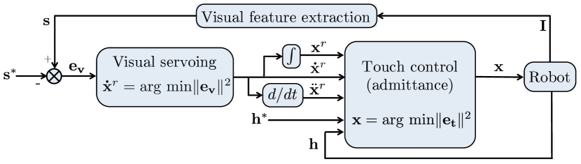
In applications where the robot and environment/human are in permanent contact (e.g. collaborative object transportation), shared control is preferable. Let us first review a pioneer controller [19] that relies on shared vision/touch, as outlined in Fig. 3; [19] addresses tele-operated peg-in-hole assembly, by placing the visual loop outside the force loop. The reference trajectory output by visual servoing is deformed in the presence of contact by the admittance controller, to obtain the robot position command . Human interaction is not considered in this work.
The authors of [91] estimate sensory-motor responses to control a pan-tilt robot head with shared visual/audio feedback from humans. They assume local linear relations between the robot motions and the ITD/ILD measures. This results in controller which is simpler than the one presented in Sect. 3.5. The scheme is similar to Fig. 3, with an outer vision loop generating a reference motion, and audio modifying it.
4.3 Hybrid Control
Pomares et al. [92] propose a hybrid vision/touch controller for grasping objects, using a robot arm equipped with a hand. Visual feedback drives an active camera (installed on the robot tip) to observe the object and detect humans to be avoided, whereas touch feedback moves the fingers, to grasp the object. The authors define matrix in (7) to independently control arm and fingers with the respective sensor.
In [93], a hybrid scheme controls an ultrasonic probe in contact with the abdomen of a patient. The goal is to centre the lesions in the ultrasound image observed by the surgeon. The probe is moved by projecting, via , the touch and vision (from the ultrasound image) tasks in orthogonal directions.
4.4 Other Control Schemes
Some works do not strictly follow the classification given above. These are reviewed below.
The authors of [81, 82] combine vision and touch to address joint human-humanoid table carrying. The table must stay flat, to prevent objects on top from falling off. Vision controls the table inclination, whereas the forces exchanged with the human make the robot follow his/her intention. The approach is shared, with visual servoing in the outer loop of admittance control (Fig. 3), to make all dof compliant. However, it is also hybrid, since some dof are controlled only with admittance. Specifically vision regulates only the table height in [81], and both table height and roll angle in [82].
The works [94, 95] merge vision and distance to guarantee lidar-based obstacle avoidance during camera-based navigation. While following a pre-taught path, the robot must avoid obstacles which were not present before. Meanwhile, it moves the camera pan angle, to maintain scene visibility. Here, the selection matrix in (19) is a scalar function dependent on the time-to-collision. In the safe context (), the robot follows the taught path, with camera looking forward. In the unsafe context () the robot circumnavigates the obstacles. Therefore, the scheme is hybrid when or (i.e., vision and distance operate on independent components of the task vector), and shared when .
In [96], proximity (distance) and tactile (touch) measurements control a robot arm in a pHRI scenario to avoid obstacles or – when contact is inevitable – to generate compliant behaviors. The framework linearly combines the two senses, and provides this signal to an inner admittance-like control loop (as in the shared scheme of Fig. 3). Since the operation principle of both senses is complementary (one requires contact while the other does not), the integration can also be seen as traded.
The authors of [97] enables a robot to adapt to changes in the human behaviour, during a human-robot collaborative screwing task. In contrast with classic hybrid vision–touch–position control, their scheme enables smooth transitions, via weighted combinations of the tasks. The robot can execute vision and force tasks, either exclusively on different dof (hybrid approach) or simultaneously (shared approach).
5 Classification of Works and Discussion
| Paper | Sense(s) | Control objective | Sector | Robot |
|---|---|---|---|---|
| [38][39] | Vision | Contactless guidance | Service | Arm |
| [40] | Vision | Remote guidance | Service | Arm |
| [41]-[43] | Vision | Contactless guidance | Medical | Wheeled |
| [44] | Vision | Contact w/humans | Medical | Arm |
| [45] | Touch | Contact w/humans | Medical | Arm |
| Remote guidance | ||||
| [46] | Touch | Contact w/humans | Medical | Arm |
| [47]-[50] | Touch | Direct guidance | Production | Arm |
| [51] | Touch | Carrying | Production | Wheeled |
| [52] | Touch | Carrying | Production | Humanoid |
| [53] | Touch | Remote guidance | Medical | Arm |
| [62][67][68] | Audition | Contactless guidance | Service | Heads |
| [64]-[66] | Audition | Contactless guidance | Service | Wheeled |
| [69]-[71] | Distance | Collision avoidance | Production | Arm |
| [72]-[74] | Distance | Collision avoidance | Service | Arm |
| [83] | V+T (tra.) | Assembly | Production | Arm |
| [84]-[86] | V+A(tra.) | Contactless guidance | Service | Heads |
| [87] | V+A(tra.) | Contactless guidance | Service | Wheeled |
| [88] | V+T+A+D | Direct guidance | Medical | Wheeled |
| (tra.) | ||||
| [89] | D+T(tra.) | Collision avoidance | Production | Arm |
| [90] | D+A(tra.) | Collision avoidance | Service | Wheeled |
| [91] | V+A(sh.) | Contactless guidance | Service | Heads |
| [92] | V+T(hyb.) | Collision avoidance | Production | Arm |
| [93] | V+T | Contact w/humans | Medical | Arm |
| (hyb.) | Remote guidance | |||
| [81][82] | V+T | Contact w/humans | Production | Humanoid |
| (sh.+hyb.) | ||||
| [94][95] | D+V | Collision avoidance | Production | Wheeled |
| (sh.+hyb.) | ||||
| [96] | D+T | Direct guidance | Service | Arm |
| (sh.+tra.) | ||||
| [97] | V+T | Assembly | Production | Arm |
| (sh.+hyb.) |
In this section, we use five criteria to classify all the surveyed papers which apply sensor-based control to collaborative robots. This taxonomy then serves as an inspiration to drive the following discussion on design choices, limitations and future challenges.
In total, we refer to the forty-five papers revised above. These include the works with only one sensor, discussed in Sect. 3 ([38]–[53], [62]–[74]) and those which integrate multiple sensors, discussed in Sect. 4 ([83]–[97]). The five criteria are: sensor(s), integration method (when multiple sensors are used), control objective, target sector and robot platform. In Table 1, we indicate these characteristics for each paper. Then, we focus on each characteristic, in Tables 2-5444In the Tables, we have used the following notation: V, T, A, D for Vision, Touch, Audition and Distance, and sh., hyb., tra. for shared, hybrid and traded..
Table 2 classifies the papers according to the sensor/s. Column mono indicates the papers relying only on one sensor. For the others, we specify the integration approach (see Sect. 4). Note that vision (alone or not) is by far the most popular sense, used in 22 papers. This comes as no surprise, since even for humans, vision provides the richest perceptual information to structure the world and perform motion [98]. Touch is the second most commonly used sensor (18 papers) and fundamental in pHRI, since it is the only one among the four that can be exploited directly to modulate contact.
Also note that, apart from [88], no paper integrates more than two sensors. Given the sensors wide accessibility and the recent progress in computation power, this is probably due to the difficulty in designing a framework capable of managing such diverse and broad data. Another reason may be the presumed (but disputable) redundancy of the three contact-less senses, which biases towards opting for vision, given its diffusion and popularity (also in terms of software). Touch – the only sensor measuring contact – is irreplaceable. This may also be the reason why, when merging two sensors, researchers have generally opted for vision+touch (7 out of 17 papers). The most popular among the three integration methods is traded control, probably because it is the easiest to set up. In recent years, however, there has been a growing interest towards the shared+hybrid combination, which guarantees nice properties in terms of control smoothness.
| Vision | [38]-[44] | ||||||
|---|---|---|---|---|---|---|---|
| Touch |
|
|
|||||
| Audition | [62]-[68] |
|
tra. [88] | ||||
| Distance |
|
|
sh.+tra. [96] | tra. [88][90] | |||
| tra. [89] | |||||||
| Mono | Vision | Touch | Audition |
An unexploited application of shared control is the combination of vision and distance (proximity sensors) to avoid collisions with humans. This can be formulated as in Fig. 3 by replacing touch control error with an admittance-like distance control error:
| (20) |
where and represent the measured and desired distance to obstacles. With this approach, the robot can stabilize at a given “safe” distance from an obstacle, or move away from it.
In the authors’ opinion, no sensor(s) nor (if needed) integration method is the best, and the designer should choose according to the objective at stake. For this, nature and evolution can be extremely inspiring but technological constraints (e.g., hardware and software availability) must also be accounted for, with the golden rule of engineering that “simpler is better”.
Table 3 classifies the papers according to the control objective. In the table, we also apply the taxonomy of pHRI layers introduced in [3], and evoked in the introduction: safety, coexistence, collaboration. Works that focus on collision avoidance address safety, and works where the robot acts on passive humans address coexistence. For the collaboration layer, we distinguish two main classes of works. First, those where the human is guiding the robot (without contact, with direct contact, or with remote physical contact as in tele-operation), then those where the two collaborate (e.g., for part assembly or object carrying). The idea (also in line with [3]) is the lower lines in the table generally require higher cognitive capabilities (e.g., better modelling of environment and task). Some works, particularly in the field of medical robotics [44, 45, 93] cover both coexistence and collaboration, since the human is guiding the robot to operate on another human. Interestingly, the senses appear in the table with a trend analogous to biology. Distance is fundamental for collision avoidance, when the human is far, and his/her role in the interaction is basic (s/he is mainly perceived as an obstacle). Then, audio is used for contactless guidance. As human and robot are closer, touch takes over the role of audio. As mentioned above, vision is a transversal sense, capable of covering most distance ranges. Yet, when contact is present (i.e., in the four lower lines), it is systematically complemented by touch, a popular pairing as also shown in Table 2 and discussed above.
| Collision avoidance | distance [69]-[74] distance+touch [89] |
|---|---|
| (safety) | distance+audition [90] vision+touch [92] |
| vision+distance [94, 95] | |
| Contact with passive humans | vision [44] touch [45, 46] |
| (coexistence) | vision+touch [93] |
| Contactless guidance | vision [38, 39], [41]-[43] |
| (collaboration) | audition [62]-[68] |
| vision+audition [84]-[87], [91] | |
| Direct guidance | touch+audition+distance+vision [88] |
| (collaboration) | touch [47]-[50] touch+distance [96] |
| Remote guidance | vision [40, 44] touch [45, 53] |
| (collaboration) | vision+touch [93] |
| Collaborative assembly | vision+touch [83, 97] |
| (collaboration) | |
| Collaborative carrying | touch [51, 52] |
| (collaboration) | vision+touch [81, 82] |
Table 4 classifies the papers according to the target (or potential) sector. We propose three sectors: Production, Medical, and Service. Production is the historical sector of robotics; applications include: manufacturing (assembly, welding, pick-and-place), transportation (autonomous guided vehicles, logistics) and construction (material and brick transfer). The medical category has become very popular in recent years, with applications spanning from robotic surgery (surgical gripper and needle manipulation), diagnosis (positioning of ultrasonic probes or endoscopes), and assistance (intelligent wheelchairs, feeding and walking aids). The service sector is the one that in the authors’ opinion presents the highest potential for growth in the coming years. Applications include companionship (elderly and child care), domestic (cleaning, object retrieving), personal (chat partners, tele-presence). The table shows that all four sensors have been deployed in all three sectors. The only exception is audition not being used in production applications, probably because of the noise – common in industrial environments.
Finally, Table 5 gives a classification based on the robotic platform. We can see that (unsurprisingly) most works use fixed base arms. The second most used platforms here are wheeled robots. Then, the humanoids category, which refers to robots with anthropomorphic design (two arms and biped locomotion capabilities). Finally, we consider robot heads, which are used exclusively for audio-based control. While robot heads are commonly used for face tracking in Social Human Robot Interaction, such works are not reviewed in this survey as they do not generally involve contact.
| Production (manufacturing, | touch [47]-[52] distance [69]-[71] |
|---|---|
| transportation, construction) | D+T [89] V+T [83][92][81][82][97] |
| V+D [94, 95] | |
| Medical (surgery, diagnosis, | vision [41]-[44] touch [45][46][53] |
| assistance) | V+T+A+D [88] V+T [93] |
| Service (companionship, | vision [38]-[40] audition [62]-[68] |
| domestic, personal) | distance [72]-[74] V+A [84]-[87], [91] |
| D+A [90] T+D [96] |
6 Conclusions
This work presents a systematic review of sensor-based controllers which enable collaboration and/or interaction between humans and robots. We considered four senses: vision, touch, audition and distance. First, we introduce a tutorial-like general formulation of sensor-based control, which we instantiate for visual servoing, touch control, aural servoing, and distance-based control, while reviewing representative papers. Next, with the same formulation, we model the methods that integrate multiple sensors, while again discussing related works. Finally, we classify the surveyed body of literature according to: used sense(s), integration method, control objective, target application and platform.
Althoug vision and touch (proprioceptive force rather than tact) emerge nowadays as the most popular senses on collaborative robots, the advent of cheap, precise and easy to integrate tactile, distance and audio sensors present great opportunities for the future. Typically, we believe that robot skins (e.g., on arms and hands) will simplify interaction, boosting the opportunities for human-robot collaboration. It is imperative that researchers develop the appropriate tools for this. Distance/proximity feedback is promising to fully perceive the human operating near the robot (something monocular vision cannot do). Audio feedback is key for developing robotic heads that can interact in a natural way with human speakers.
| Arms | vision [38]-[40], [44] touch [45]-[50], [53] distance [69]-[74] |
|---|---|
| V+T [83, 92, 93, 97] D+T [89, 96] | |
| vision [41]-[43] touch [51] audition [64]-[66] | |
| Wheeled | V+A [87] V+T+A+D [88] D+A [90] V+D [94, 95] |
| Humanoids | touch [52] V+T [81, 82] |
| Heads | audition [62, 67, 68] V+A [84]- [86] [91] |
Finally, some open problems must be addressed, to develop robust controllers for real-world applications. For example, the use of task constraints has not been sufficiently explored when multiple sensors are integrated. Also, difficulty in obtaining models describing and predicting human behavior hampers the implementation of human-robot collaborative tasks. The use of multimodal data such as RGB-D cameras with multiple proximity sensors may be an interesting solution for this human motion sensing and estimation problem. More research needs to be conducted in this direction.
References
- [1] A. Bicchi, M. Peshkin, and J. Colgate, “Safety for physical human-robot interaction,” Springer Handbook of Robotics, B. Siciliano and O. Khatib (Eds.), Springer, pp. 1335-1348, 2008.
- [2] J. Colgate, W. Wannasuphoprasit, and M. Peshkin, “Cobots: robots for collaboration with human operators,” in Proc ASME Dynamic Systems and Control Division, vol. 58. ASME, 12 1996, pp. 433–439.
- [3] A. De Luca and F. Flacco, “Integrated control for pHRI: collision avoidance, detection, reaction and collaboration,” in IEEE RAS/EMBS Int. Conf. on Biomedical Robotics and Biomechatronics, BIOROB, 2012.
- [4] “ISO 13482:2014 Robots and robotic devices - Safety requirements for personal care robots,” International Organization for Standardization, Geneva, Switzerland, Tech. Rep., 2014.
- [5] O. Khatib, “Real-time obstacle avoidance for manipulators and mobile robots,” in IEEE Int. Conf. on Robotics and Automation, ICRA, 1985.
- [6] M. Azizian, M. Khoshnam, N. Najmaei, and R. V. Patel, “Visual Servoing in medical robotics: a survey. Part I: endoscopic and direct vision imaging – techniques and applications,” Int. J. of Med. Robot., vol. 10, no. 3, pp. 263–274, 2014.
- [7] S. Phoha, “Machine perception and learning grand challenge: Situational intelligence using cross-sensory fusion,” Frontiers in Robotics and AI, vol. 1, p. 7, 2014.
- [8] S. M. La Valle, Planning Algorithms. Cambridge Univ. Press, 2006.
- [9] F. Chaumette and S. Hutchinson, “Visual servo control, Part I: Basic approaches,” IEEE Robotics and Automation Magazine, vol. 13, no. 4, pp. 82–90, 2006.
- [10] A. Berthoz, The brain’s sense of movement. Harvard Univ. Press, 2002.
- [11] E. Davison and A. Goldenberg, “Robust control of a general servomechanism problem: The servo compensator,” IFAC Proceedings Volumes, vol. 8, no. 1, Part 1, pp. 231 – 239, 1975.
- [12] A. Ajoudani, A. M. Zanchettin, S. Ivaldi, A. Albu-Schäffer, K. Kosuge, and O. Khatib, “Progress and prospects of the human–robot collaboration,” Autonomous Robots, vol. 42, pp. 957–975, Oct 2017.
- [13] V. Villani, F. Pini, F. Leali, and C. Secchi, “Survey on human–robot collaboration in industrial settings: Safety, intuitive interfaces and applications,” Mechatronics, vol. 55, pp. 248–266, 2018.
- [14] S. Haddadin, A. De Luca, and A. Albu-Schäffer, “Robot collisions: A survey on detection, isolation, and identification,” IEEE Trans. on Robotics, vol. 33, no. 6, pp. 1292 – 1312, 2017.
- [15] U. Proske and S. C. Gandevia, “The proprioceptive senses: their roles in signaling body shape, body position and movement, and muscle force,” Physiol Rev., vol. 92, no. 4, pp. 1651–1697, 2012.
- [16] N. Hogan, “Impedance control: an approach to manipulation: parts I-III,” ASME Journal of Dynamic Systems, Measurement, and Control, vol. 107, pp. 1–24, 1985.
- [17] L. Villani and J. De Schutter, “Force Control,” in Springer Handbook of Robotics, B. Siciliano and O. Khatib, Eds. Springer, 2008, ch. 7, pp. 161–185.
- [18] M. H. Raibert and J. J. Craig, “Hybrid position/force control of manipulators,” ASME J. Dyn. Syst. Meas. Control, no. 103, pp. 126–133, 1981.
- [19] G. Morel, E. Malis, and S. Boudet, “Impedance based combination of visual and force control,” in IEEE Int. Conf. on Robotics and Automation, ICRA, vol. 2, 1998, pp. 1743–1748.
- [20] N. Wettels, V. J. Santos, R. S. Johansson, and G. Loeb, “Biomimetic tactile sensor array,” Advanced Robotics, vol. 22(8), pp. 829–849, 2008.
- [21] A. Schmitz, P. Maiolino, M. Maggiali, L. Natale, G. Cannata, and G. Metta, “Methods and technologies for the implementation of large-scale robot tactile sensors,” IEEE Trans. on Robotics, vol. 27(3), pp. 389 – 400, 2011.
- [22] L. Rayleigh, “On our perception of sound direction,” The London, Edinburgh, and Dublin Philosophical Magazine and Journal of Science, vol. 13, no. 74, pp. 214–232, 1907.
- [23] K. Nakadai, H. Nakajima, M. Murase, S. Kaijiri, K. Yamada, T. Nakamura, Y. Hasegawa, H. G. Okuno, and H. Tsujino, “Robust tracking of multiple sound sources by spatial integration of room and robot microphone arrays,” in IEEE Int. Conf. on Acoustics Speech and Signal Processing, 2006.
- [24] D. Göger, M. Blankertz, and H. Wörn, “A tactile proximity sensor,” IEEE Sensors, pp. 589–594, 2010.
- [25] G. Kowadlo and R. A. Russell, “Robot odor localization: A taxonomy and survey,” Int. Journal of Robotics Research, vol. 27, no. 8, pp. 869–894, 2008.
- [26] R. A. Russell, “Tracking chemical plumes in 3-dimensions,” in IEEE Int. Conf. on Robotics and Biomimetics, 2006, pp. 31–36.
- [27] B. Gao, H. Li, W. Li, and F. Sun, “3D moth-inspired chemical plume tracking and adaptive step control strategy,” Adaptive Behavior, vol. 24, no. 1, pp. 52–65, 2016.
- [28] F. Rahbar, A. Marjovi, P. Kibleur, and A. Martinoli, “A 3-D bio-inspired odor source localization and its validation in realistic environmental conditions,” in IEEE/RSJ Int. Conf. on Robots and Intelligent Systems, IROS, 2017, pp. 3983–3989.
- [29] H. Shimazu, K. Kobayashi, A. Hashimoto, and T. Kameoka, “Tasting robot with an optical tongue: Real time examining and advice giving on food and drink,” in Human Interface and the Management of Information. Methods, Techniques and Tools in Information Design, M. J. Smith and G. Salvendy, Eds. Springer Berlin Heidelberg, 2007.
- [30] Y. Kobayashi, M. Habara, H. Ikezazki, R. Chen, Y. Naito, and K. Toko, “Advanced taste sensors based on artificial lipids with global selectivity to basic taste qualities and high correlation to sensory scores,” Sensors, vol. 10, no. 4, pp. 3411–3443, 2010.
- [31] D. Ha, Q. Sun, K. Su, H. Wan, H. Li, N. Xu, F. Sun, L. Zhuang, N. Hu, and P. Wang, “Recent achievements in electronic tongue and bioelectronic tongue as taste sensors,” Sensors and Actuators Part B: Chemical, vol. 207, pp. 1136 – 1146, 2015.
- [32] A. Wilson and S. Golonka, “Embodied cognition is not what you think it is,” Frontiers Psych., vol. 4, p. 58, 2013.
- [33] L. Shapiro, Embodied Cognition, ser. New Problems of Philosophy. Taylor & Francis, 2010.
- [34] B. V. H. Saxberg, “Projected free fall trajectories,” Biol. Cyber., vol. 56, no. 2, pp. 159–175, May 1987.
- [35] M. McBeath, D. Shaffer, and M. Kaiser, “How baseball outfielders determine where to run to catch fly balls,” Science, vol. 268, no. 5210, pp. 569–573, 1995.
- [36] D. Whitney, “Resolved motion rate control of manipulators and human prostheses,” IEEE Trans. Man-Mach. Syst., vol. 10(2), pp. 47–53, 1969.
- [37] J. Nocedal and S. Wright, Numerical Optimization, ser. Springer Series in Operations Research and Financial Engineering, 2000.
- [38] C. Cai, N. Somani, and A. Knoll, “Orthogonal image features for visual servoing of a 6-dof manipulator with uncalibrated stereo cameras,” IEEE Trans. on Robotics, vol. 32, no. 2, pp. 452–461, April 2016.
- [39] M. Gridseth, O. Ramirez, C. P. Quintero, and M. Jagersand, “Vita: Visual task specification interface for manipulation with uncalibrated visual servoing,” in IEEE Int. Conf. on Robotics and Automation, ICRA, 2016.
- [40] M. Gridseth, K. Hertkorn, and M. Jagersand, “On visual servoing to improve performance of robotic grasping,” in Conf. on Computer and Robot Vision, June 2015, pp. 245–252.
- [41] V. K. Narayanan, F. Pasteau, M. Marchal, A. Krupa, and M. Babel, “Vision-based adaptive assistance and haptic guidance for safe wheelchair corridor following,” Comput. Vis. Image Underst., vol. 149, no. C, pp. 171–185, Aug. 2016.
- [42] K. M. Tsui, D.-J. Kim, A. Behal, D. Kontak, and H. A. Yanco, “I want that: Human-in-the-loop control of a wheelchair-mounted robotic arm,” Appl. Bionics Biomechanics, vol. 8, no. 1, pp. 127–147, Jan. 2011.
- [43] C. Dune, A. Remazeilles, E. Marchand, and C. Leroux, “Vision-based grasping of unknown objects to improve disabled people autonomy.” in Robotics: Science and Systems, 2008.
- [44] A. Agustinos, R. Wolf, J. A. Long, P. Cinquin, and S. Voros, “Visual servoing of a robotic endoscope holder based on surgical instrument tracking,” in IEEE RAS/EMBS Int. Conf. on Biomedical Robotics and Biomechatronics, Aug 2014, pp. 13–18.
- [45] E. Bauzano, B. Estebanez, I. Garcia-Morales, and V. F. Munoz, “Collaborative human-robot system for HALS suture procedures,” IEEE Systems Journal, vol. 10, no. 3, pp. 957–966, Sept 2016.
- [46] R. Cortesao and M. Dominici, “Robot force control on a beating heart,” IEEE/ASME Transactions on Mechatronics, vol. 22, no. 4, pp. 1736–1743, Aug 2017.
- [47] Y. Maeda, T. Hara, and T. Arai, “Human-robot cooperative manipulation with motion estimation,” in IEEE/RSJ Int. Conf. on Robots and Intelligent Systems, IROS, vol. 4, 2001, pp. 2240–2245.
- [48] M. Suphi Erden and T. Tomiyama, “Human intent detection and physically interactive control of a robot without force sensors,” IEEE Trans. on Robotics, vol. 26, no. 2, pp. 370–382, 2010.
- [49] M. Suphi Erden and B. Maric, “Assisting manual welding with robot,” Robotics and Computer Integrated Manufacturing, vol. 27, pp. 818–828, 2011.
- [50] F. Ficuciello, A. Romano, L. Villani, and B. Siciliano, “Cartesian impedance control of redundant manipulators for human-robot co-manipulation,” in IEEE/RSJ Int. Conf. on Robots and Intelligent Systems, IROS, 2013.
- [51] Y. Wang, C. Smith, Y. Karayiannidis, and P. Ögren, “Cooperative control of a serial-to-parallel structure using a virtual kinematic chain in a mobile dual-arm manipulation application,” in IEEE/RSJ Int. Conf. on Robots and Intelligent Systems, IROS, Sept 2015, pp. 2372–2379.
- [52] A. Bussy, A. Kheddar, A. Crosnier, and F. Keith, “Human-humanoid haptic joint object transportation case study,” in IEEE/RSJ Int. Conf. on Robots and Intelligent Systems, IROS, 2012, pp. 3633–3638.
- [53] J. Baumeyer, P. Vieyres, S. Miossec, C. Novales, G. Poisson, and S. Pinault, “Robotic co-manipulation with 6 dof admittance control: Application to patient positioning in proton-therapy,” in IEEE Int. Work. on Advanced Robotics and its Social Impacts, June 2015, pp. 1–6.
- [54] C. Passenberg, A. Peer, and M. Buss, “A survey of environment- operator- and task-adapted controllers for teleoperation systems,” Mechatronics, vol. 20, no. 7, pp. 787 – 801, 2010.
- [55] B. D. Argall and A. G. Billard, “A survey of tactile human-robot interactions,” Robotics and Autonomous Systems, vol. 58, no. 10, pp. 1159 – 1176, 2010.
- [56] L. Natale and E. Torres-Jara, “A sensitive approach to grasping,” in Proc. of the 6th Int. Workshop on Epigenetic Robotics, 2006.
- [57] Z. Abderrahmane, G. Ganesh, A. Crosnier, and A. Cherubini, “Haptic zero-shot learning: Recognition of objects never touched before,” Robotics and Autonomous Systems, vol. 105, pp. 11–25, 2018.
- [58] A. Del Prete, S. Denei, L. Natale, F. Mastrogiovanni, F. Nori, G. Cannata, and G. Metta, “Skin spatial calibration using force/torque measurements,” in IEEE/RSJ Int. Conf. on Robots and Intelligent Systems, IROS, 2011.
- [59] C. H. Lin, J. A. Fishel, and G. E. Loeb, “Estimating point of contact, force and torque in a biomimetic tactile sensor with deformable skin,” SynTouch LLC, Tech. Rep., 2013.
- [60] Q. Li, C. Schürman, R. Haschke, and H. Ritter, “A control framework for tactile servoing,” in Robotics: Science and Systems (RSS), 2013.
- [61] H. Zhang and N. N. Chen, “Control of contact via tactile sensing,” IEEE Trans. on Robotics and Automation, vol. 16(5), pp. 482–495, Oct 2000.
- [62] A. Magassouba, N. Bertin, and F. Chaumette, “Binaural auditory interaction without HRTF for humanoid robots: A sensor-based control approach,” in See, Touch, and Hear: 2nd Workshop on Multimodal Sensor-based Robot Control for HRI and Soft Manipulation, IROS, 2016.
- [63] K. Youssef, S. Argentieri, and J. L. Zarader, “Towards a systematic study of binaural cues,” in IEEE/RSJ Int. Conf. on Robots and Intelligent Systems, IROS, 2012, pp. 1004–1009.
- [64] A. Magassouba, N. Bertin, and F. Chaumette, “Sound-based control with two microphones,” in IEEE/RSJ Int. Conf. on Robots and Intelligent Systems, IROS, Sept 2015, pp. 5568–5573.
- [65] ——, “First applications of sound-based control on a mobile robot equipped with two microphones,” in IEEE Int. Conf. on Robotics and Automation, ICRA, May 2016, pp. 2557–2562.
- [66] ——, “Audio-based robot control from interchannel level difference and absolute sound energy,” in IEEE/RSJ Int. Conf. on Robots and Intelligent Systems, IROS, Oct 2016, pp. 1992–1999.
- [67] M. Kumon, T. Sugawara, K. Miike, I. Mizumoto, and Z. Iwai, “Adaptive audio servo for multirate robot systems,” in IEEE/RSJ Int. Conf. on Robots and Intelligent Systems, IROS, vol. 1, Oct 2003, pp. 182–187.
- [68] M. Kumon, T. Shimoda, R. Kohzawa, I. Mizumoto, and Z. Iwai, “Audio servo for robotic systems with pinnae,” in IEEE/RSJ Int. Conf. on Robots and Intelligent Systems, IROS, Aug 2005, pp. 1881–1886.
- [69] A. De Santis, V. Lippiello, B. Siciliano, and L. Villani, “Human-robot interaction control using force and vision,” Advances in Control Theory and Applications, vol. 353, pp. 51–70, 2007.
- [70] F. Flacco, T. Kroger, A. De Luca, and O. Khatib, “A Depth Space Approach to Human-Robot Collision Avoidance,” in IEEE Int. Conf. on Robotics and Automation, ICRA, 2012.
- [71] T. Schlegl, T. Kröger, A. Gaschler, O. Khatib, and H. Zangl, “Virtual whiskers – highly responsive robot collision avoidance,” in IEEE/RSJ Int. Conf. on Robots and Intelligent Systems, IROS, 2013.
- [72] F. Bergner, E. Dean-Leon, and G. Cheng, “Efficient event-driven reactive control for large scale robot skin,” in IEEE Int. Conf. on Robotics and Automation, ICRA, May 2017, pp. 394–400.
- [73] Q. Leboutet, E. Dean-León, and G. Cheng, “Tactile-based compliance with hierarchical force propagation for omnidirectional mobile manipulators,” in IEEE-RAS Int. Conf. on Humanoid Robots, 2016.
- [74] E. Dean-Leon, B. Pierce, F. Bergner, P. Mittendorfer, K. Ramirez-Amaro, W. Burger, and G. Cheng, “TOMM: Tactile omnidirectional mobile manipulator,” in IEEE Int. Conf. on Robotics and Automation, ICRA, May 2017, pp. 2441–2447.
- [75] M. O. Ernst and M. S. Banks, “Humans integrate visual and haptic information in a statistically optimal fashion,” Nature, vol. 415, pp. 429–433, 2002.
- [76] R. Smits, T. De Laet, K. Claes, H. Bruyninckx, and J. De Schutter, “iTASC: a tool for multi-sensor integration in robot manipulation,” in IEEE International Conference on Multisensor Fusion and Integration for Intelligent Systems, 2008, pp. 426–433.
- [77] G. Taylor and L. Kleeman, Visual Perception and Robotic Manipulation: 3D Object Recognition, Tracking and Hand-Eye Coordination, ser. Springer Tracts in Advanced Robotics. Springer, 2006.
- [78] B. J. Nelson and P. K. Khosla, “Force and vision resolvability for assimilating disparate sensory feedback,” IEEE Trans. on Robotics and Automation, vol. 12, no. 5, pp. 714–731, 1996.
- [79] B. J. Nelson, J. D. Morrow, and P. K. Khosla, “Improved force control through visual servoing,” in Proc. of the American Control Conference, vol. 1. IEEE, 1995, pp. 380–386.
- [80] J. Baeten, H. Bruyninckx, and J. De Schutter, “Integrated vision/force robotic servoing in the task frame formalism,” Int. Journal of Robotics Research, vol. 22, no. 10-11, pp. 941–954, 2003.
- [81] D. J. Agravante, A. Cherubini, A. Bussy, and A. Kheddar, “Human-humanoid joint haptic table carrying task with height stabilization using vision,” in IEEE/RSJ Int. Conf. on Robots and Intelligent Systems, IROS, 2013.
- [82] D. J. Agravante, A. Cherubini, A. Bussy, P. Gergondet, and A. Kheddar, “Collaborative human-humanoid carrying using vision and haptic sensing,” in IEEE Int. Conf. on Robotics and Automation, ICRA, 2014.
- [83] A. Cherubini, R. Passama, A. Crosnier, A. Lasnier, and P. Fraisse, “Collaborative manufacturing with physical human-robot interaction,” Robotics and Computer-Integrated Manufacturing, vol. 40, pp. 1–13, August 2016.
- [84] H. G. Okuno, K. Nakadai, K. I. Hidai, H. Mizoguchi, and H. Kitano, “Human-robot interaction through real-time auditory and visual multiple-talker tracking,” in IEEE/RSJ Int. Conf. on Robots and Intelligent Systems, IROS, vol. 3, 2001, pp. 1402–1409.
- [85] H. G. Okuno, K. Nakadai, T. Lourens, and H. Kitano, “Sound and visual tracking for humanoid robot,” Applied Intelligence, vol. 20, no. 3, pp. 253–266, May 2004.
- [86] J. Hornstein, M. Lopes, J. Santos-Victor, and F. Lacerda, “Sound localization for humanoid robots - building audio-motor maps based on the HRTF,” in IEEE/RSJ Int. Conf. on Robots and Intelligent Systems, IROS, Oct 2006, pp. 1170–1176.
- [87] V. Chan, C. Jin, and A. van Schaik, “Neuromorphic audio-visual sensor fusion on a sound-localising robot,” Frontiers in Neuroscience, vol. 6, p. 21, 2012.
- [88] X. S. Papageorgiou, C. S. Tzafestas, P. Maragos, G. Pavlakos, G. Chalvatzaki, G. Moustris, I. Kokkinos, A. Peer, B. Stanczyk, E.-S. Fotinea, and E. Efthimiou, “Advances in intelligent mobility assistance robot integrating multimodal sensory processing,” in Universal Access in Human-Computer Interaction. Aging and Assistive Environments. Springer International Publishing, 2014, pp. 692–703.
- [89] S. E. Navarro, M. Schonert, B. Hein, and H. WWörn, “6D proximity servoing for preshaping and haptic exploration using capacitive tactile proximity sensors,” in IEEE/RSJ Int. Conf. on Robots and Intelligent Systems, IROS, 2014.
- [90] J. Huang, T. Supaongprapa, I. Terakura, F. Wang, N. Ohnishi, and N. Sugie, “A model-based sound localization system and its application to robot navigation,” Robotics and Autonomous Systems, vol. 27, no. 4, pp. 199 – 209, 1999.
- [91] L. Natale, G. Metta, and G. Sandini, “Development of auditory-evoked reflexes: Visuo-acoustic cues integration in a binocular head,” Robotics and Autonomous Systems, vol. 39, no. 2, pp. 87 – 106, 2002.
- [92] J. Pomares, I. Perea, G. J. García, C. A. Jara, J. A. Corrales, and F. Torres, “A multi-sensorial hybrid control for robotic manipulation in human-robot workspaces,” Sensors, vol. 11, no. 10, pp. 9839–9862, 2011.
- [93] P. Chatelain, A. Krupa, and N. Navab, “Confidence-driven control of an ultrasound probe,” IEEE Transactions on Robotics, vol. 33, no. 6, pp. 1410–1424, Dec 2017.
- [94] A. Cherubini and F. Chaumette, “Visual navigation of a mobile robot with laser-based collision avoidance.” Int. Journal of Robotics Research, vol. 32, no. 2, pp. 189–209, 2013.
- [95] A. Cherubini, F. Spindler, and F. Chaumette, “Autonomous visual navigation and laser-based moving obstacle avoidance,” IEEE Trans. on Int. Transportation Systems, vol. 15, no. 5, pp. 2101–2110, 2014.
- [96] E. Dean-Leon, F. Bergner, K. Ramirez-Amaro, and G. Cheng, “From multi-modal tactile signals to a compliant control,” in IEEE-RAS Int. Conf. on Humanoid Robots, Nov 2016, pp. 892–898.
- [97] A. Cherubini, R. Passama, P. Fraisse, and A. Crosnier, “A unified multimodal control framework for human-robot interaction,” Robotics and Autonomous Systems, vol. 70, pp. 106–115, 2015.
- [98] D. Hoffman, Visual Intelligence: How We Create what We See. W. W. Norton and Company, 1998.