Droplet impact on surfaces with asymmetric microscopic features
Abstract
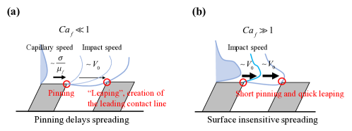
The impact of liquid drops on a rigid surface is central in cleaning, cooling and coating processes in both nature and industrial applications. However, it is not clear how details of pores, roughness and texture on the solid surface influence the initial stages of the impact dynamics. Here, we experimentally study drop impacting at low velocities onto surfaces textured with asymmetric (tilted) ridges. We define the line-friction capillary number (where , and are the line friction, impact velocity and surface tension, respectively) as a measure of the importance of the topology of surface textures for the dynamics of droplet impact. We show that when , the contact line speed in the direction against the inclination of the ridges is set by line-friction, whereas in the direction with inclination the contact line is pinned at acute corners of the ridge. When , the pinning is only temporary until the liquid-vapor interface reaches to the next ridge where a new contact line is formed. Finally, when , the geometric details of non-smooth surfaces play little role.
I Introduction
Droplet impact on a solid surface is essential in technological applications such as spray coating and cooling[1, 2], pesticide deposition[3, 4], and inkjet printing[5, 6]. The complex fluid-surface interaction during the impact – which includes splashing[7, 8, 9, 10, 11] and trapping of a thin gas film underneath the droplet[12, 13, 14, 15] – has been studied theoretically[16, 17, 18, 19], numerically[19, 20, 18, 21], and experimentally[22, 23, 24, 25, 26, 27]. These studies have established useful scaling laws of maximal deformation, which among other things, are reviewed in [28, 2].
The influence of surface roughness and microstructures on drop impact has also been studied extensively focusing on different aspects, such as splashing[23, 29, 30], bouncing[31, 32, 33, 34], trapped gas film under the droplet[14], and the maximum spreading radius[25, 26, 35, 36]. These studies have reported that surface topology influences the spreading and even small roughness delays spreading at a low impact velocity[25]. However, it is not completely understood which microscopic features of a complex surface texture have the largest influence on droplet impact.
One example of a complex surface is an symmetric textured surface, i.e. where the unit structure (post, ridge, rising, etc) is not mirror symmetric with respect to the vertical line passing through the center of structure. Asymmetric surface textures are used by natural organisms to control approaching rain drops[4]. For example, the slanted microgrooves on the peristrome of the ”pitcher plant” Nepenthes alata[37, 38, 39], do not only assist to maintain the surface wetted, but they also prevent drops from falling into the pitcher tank[40]. Although these asymmetric surface structures have been mimicked for technical applications such as oil-water separation[41] and raindrop shielding[40], their influence on droplet impact is not fully understood.
Here, we perform experiments of a droplet impacting a surface with asymmetric microstructures. We measure the spreading radius in different surface-parallel directions and quantify the droplet asymmetry by introducing a line-friction capillary number , where and are the impact velocity and surface tension, respectively, and is the local friction at the moving vapor/liquid/solid phase contact line. As constitutes the key ingredient in our analysis (in contrast to earlier models[17, 18, 26]), we first briefly summarize the notion of contact-line friction, before discussing the scope of the present study.
I.1 Contact-line friction
When a moving contact line exhibits a dynamic contact angle different from the static value we expect a local dissipation at the contact line. de Gennes 1985[42] (eq. 4.71, p860) introduced a local dissipation proportional to near the moving contact line, where is the contact line speed and is a ’simple friction coefficient’ with the same dimensions as viscosity (denoted in de Gennes’ original paper). This dissipation is expected from fundamental principles of thermodynamics, and it can have different molecular or hydrodynamic origins. Assuming a microscopic cut-off region where fluid slip is allowed[43], the dissipation due to slip and viscous friction in the vicinity of the contact line can be viewed as a local dissipation. Under different circumstances, the moving contact line can be treated as a thermally activated process, which is the basis for the molecular kinetic theory (MKT)[44, 45]. See the recent reviews[46, 47] for discussions of these and other possibilities.
Regardless of its molecular origin, the parameter can be treated as a macroscopically relevant parameter that characterizes the contribution to the total dissipation from processes that are local to the contact line region. As such, it is expected to depend on the combination of the liquid and the substrate properties, as well as on the local dynamic contact angle, but not otherwise on the flow geometry. Equivalent parameters have been introduced and used in the literature, for instance as a linearization of an assumed smooth dependence of contact line speed on dynamic contact angle[48]. Yue and Feng discussed contact line dissipation in the Cahn-Hilliard model, and derived the resulting relation between contact line speed and the dynamic contact angle. Their relation, in our notation, is[49]
| (1) |
where is the static contact angle, the dynamic contact angle, and the surface tension.
The contact line friction coefficient can be measured experimentally[50, 51, 52] or estimated by parameter fitting of numerical simulations to experiments[53, 54]. Steen[55, 56] recently used driven droplet oscillations to estimate the magnitude of the contact line friction coefficient. The values of the line friction parameter in previous studies are in the order of 0.1 Pas for water and increase in proportion to the square root of the liquid viscosity up to 1 Pas[57, 53, 51]. Since is much larger than liquid viscosity for most aqueous solutions[53, 57, 50], the contact line friction plays a particularly dominant role in dynamic and forced wetting applications.
The sensitivity of the line friction parameter to surface properties has been investigated thoroughly within the context of spontaneous spreading (i.e. zero impact speed). The relevant non-dimensional number in liquid spreading is the line-friction Ohnesorge number [57], where and are density and the initial radius of the droplet, respectively. The line-friction Ohnesorge number quantifies the contribution of the line friction dissipation to the total kinetic energy. One may therefore expect that when the contact line speed is strongly influenced by the properties of the substrate and in particular the details of the surface geometry. In this surface-sensitive regime, Carlson et al.[53] have shown that when the time is normalized with the time scale based on the line friction parameter, the initial rapid spreading of different droplets on smooth surfaces nearly collapse into one curve. For non-smooth surfaces, one may define an effective line friction parameter that takes geometric surface details into account. Based on this parameter, one may normalize time such that the spreading curves of different droplets on microstructures exhibit nearly the same scaling[58, 54, 59].
I.2 Scope of the present study
For droplet impact on smooth surfaces, Wang et al.[60] rescaled previous experimental data with contact-line friction to demonstrate that line friction limits the maximum spreading radius . They suggested the scaling , where is liquid viscosity and is Reynolds number. However, to the best of our knowledge, no study has linked the spreading mechanism on microstructures to the spreading resistance involving the line friction during droplet impact.
In our previous work[59], the spontaneous spreading of a droplet on slanted microstructures (see inset in Fig. 2a) was explained by mechanisms referred to as slip, stick and leap. The spreading in the direction against the inclination (indicated by red arrow in Fig. 2a) was driven by the slip mechanism, i.e. a so-called “capillary spreading” driven by uncompensated Young’s force (Eq. 1). In the direction with the inclination (indicated by blue arrow in Fig. 2a), the contact line motion could be explained by a combination of slip, stick and leap; the contact line is pinned at the acute corner of the surface microstructures and the average spreading velocity is set by a combination of the capillary spreading on the flat fraction of the surface and ”leaping” of the contact line to the next rise of the surface after the pinning. Here, a length scale separation between the droplet size and the microstructures is assumed so that the spreading mechanisms can be considered local at the contact line.
In this work, we investigate the same microstructured surface as studied by [59], but now for impacting drops, which introduces the impact velocity as an additional parameter. This allows us to define a new measure of the spreading delay by the surface structures that consists of the ratio between and the characteristic velocity . As shown in Fig. 1b, a large impact speed results in a fast leap of the contact line to the next ridge, which effectively means that the underlying microscropic features of the surface geometry have a small influence on droplet impact. On the other hand, when is very small compared to the contact line motion is significantly influenced by both pinning and line friction (Fig. 1a). We therefore propose that the line-friction capillary number, is the relevant non-dimensional number to characterize the influence of asymmetric surface geometry on droplet impact. Note that, despite the fact that the impact of spherical drop on two-dimensional ridges is a three dimensional problem, this study focuses on the local two-dimensional spreading across the asymmetric ridges. This can be motivated by the fact that the curvature of the liquid-vapor interface in the cross-sectional plane is much smaller than the curvature in the horizontal plane.
II Method
II.1 Experimental setup
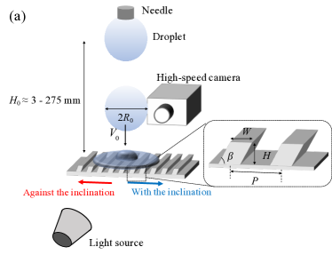
Impact sequences of liquid droplets are observed with a high-speed camera (Dantek Speedsense M) at a frame rate of 8000 with spatial resolution of 15 m. A schematic of the experimental set up is shown in Fig. 2(a). A liquid droplet is formed on the tip of a needle with outer diameter of 0.31 mm (Hamilton, Gauge 30, point style 3) at a height from surfaces to spread on. The liquid is pumped by a syringe pump (Cetoni, neMESYS 1000N) at a small flow rate (0.10 l/s). When the growing droplet has reached a certain radius, it pinches off from the needle and is accelerated by gravity and hits the substrate with an impact velocity . The impact velocities, which are varied by changing the distance from the substrate to the needle , are estimated from images before the droplet makes contact with the substrate. The height is varied from 3 mm to 275 mm, which leads to the velocities from 0.16 m/s to 2.3 m/s (table 1). Spontaneous spreading corresponding to = 0 m/s (=0 mm) is also measured. Fluid properties were varied by mixing de-ionized water, ethanol and glycerol to change viscosity and surface tension. We label mixtures of water, glycerol and ethanol (weight ratio of 1:2:1) and water and glycerol (weight ratio of 1:2) as ”aq. glycerol-ethanol” and ”aq. glycerol”, respectively. Fluid properties are shown in Table 2. Viscosity and surface tension are measured with a viscometer (Brookfield) and TD 2 tensionmeter (LAUDA), respectively.

| (mm) | 3 | 5 | 10 | 25 | 40 | 135 | 275 |
|---|---|---|---|---|---|---|---|
| (m/s) | 0.16 | 0.25 | 0.37 | 0.69 | 0.87 | 1.6 | 2.3 |
| for water | 0.27 | 0.42 | 0.62 | 1.2 | 1.5 | 2.7 | 3.8 |
| for aq. glycerol-ethanol | 0.67 | 1.0 | 1.5 | 2.9 | 3.6 | 6.7 | 9.6 |
| for aq. glycerol | 0.89 | 1.4 | 2.1 | 3.8 | 4.8 | 8.9 | 12.8 |
| Label | \textrho | µ | \textsigma | ||||||
|---|---|---|---|---|---|---|---|---|---|
| (kg/m3) | (mPa s) | (mN/m) | (mm) | (∘) | (∘) | (∘) | (Pa s) | (m/s) | |
| Water | 992 | 0.997 | 72 | 1.1 | 50 | 70 | 27 | 0.12 | 0.60 |
| Aq. glycerol-ethanol | 1077 | 11.7 | 34 | 0.9 | 34 | 59 | 22 | 0.14 | 0.24 |
| Aq. glycerol | 1170 | 15.7 | 63 | 1.0 | 54 | 66 | 28 | 0.36 | 0.18 |
II.2 Surface preparation
The substrates studied are made from Ostemer 220 (Mercene Labs), a UV-curing Off-Stoichiometry-Thiol-Ene (OSTE) resin[61]. The resin enables to fabricate inclined micropatterns by exposing UV light at an oblique angle. The surfaces are prepared in three steps. First, a base OSTE layer is prepared on a smooth plastic film. Second, inclined microridges are patterned on the base OSTE layer by exposing ultraviolet light through a patterned mask. Finally, after cleaning uncured OSTE in an acetone bath, hydrophilic surface modification using 1% hydroxylated methacrylate (2-Hydroxyethyl methacrylate, Sigma Aldrich) solution in Isopropanol with 0.05% benzophenone (Sigma-Aldrich) initiator is performed to achieve partial wetting so that the static contact angle on a flat surface is for de-ionized water. Advancing and receding contact angles are measured with the sessile drop method[62]. The sessile droplet with the initial volume is pumped and drained slowly to measure advancing and receding contact angle, respectively. The contact angle right before the contact line starts to advance (recede) is defined as the advancing (receding) contact angle. The inclination of the ridges is 60∘. Surface structures are characterized with scanning electron microscopy and the width is 20 , the pitch is 60 , and the height is 20 , as shown in Fig. 2(b).
II.3 Estimates of line friction parameter
Experiments of a droplet spreading on a flat OSTE surface are modelled numerically to determine the line friction parameter. The line friction parameter is determined by fitting the spreading curve with the experiments. Spreading of a droplet on a flat surface is experimentally observed with a high-speed camera at a frame rate of 52000 and the spreading radius and the spreading time are recorded. To enhance sensitivity to the line friction parameter[57], we reduce the initial radius to 0.4 mm.
Navier-Stokes-Cahn-Hilliard equations are solved using in-house software “FemLego” to obtain the spreading radius for different values of . FemLego is an adaptive finite element toolbox where weak formulation of partial differential equations is defined on a MAPLE worksheet[63]. The numerical model is composed of the Navier-Stokes equations and the Cahn-Hilliard equation;
| (2) |
| (3) |
| (4) |
The Navier-Stokes equations are characterized by the capillary number =, the Reynolds number =, and the Cahn number =, where and are the density and viscosity of the liquid phase, is the surface tension of the liquid-vapor interface, and is the diffuse interface width. Moreover, and are the characteristic velocity and length of the system, respectively. Here, capillary velocity and the initial droplet radius are chosen as the characteristic velocity and length scale. The variable is the phase field variable, where represents the liquid phase, and the vapor phase.
In the Cahn-Hilliard equation (4), is the chemical potential of the system defined as . Here, is the double well function, where the minimum represents the stable phases for vapor () and liquid (). The Peclet number is defined as where is a mass diffusivity.
The line friction parameter appears as a boundary condition in the Navier-Stokes-Cahn-Hilliard equations in the form[64, 65]
| (5) |
where is static contact angle. The polynomial rapidly shifts from (vapor phase ) to (liquid phase ). The left hand side of Eq.5 models the dissipation at the moving contact line.
The only unknown parameter in the numerical simulation is the line friction parameter. We impose the no-slip boundary condition at the wall for the velocity and Eq. 5 as the wall boundary condition for the phase-field variable . Therefore, the local effect at the contact line is effectively modeled in the line friction parameter in this work. Fluid properties in Table 2 are used in the simulations to match to the experimental spreading rates. The mass diffusivity in Eq. 4 is fixed to 5.7 for all of our simulations. The interface width is determined following the guidance to maintain the sharp interface limit[66]. The fitted line friction parameters are reported in Table 2. The simulations are carried out in the axi-symmetric geometry along the center of the droplet. The line friction parameter increases with kinematic viscosity from 0.12 Pas (water) to 0.36 Pas (aq. glycerol).
II.4 Numerical simulation of droplet impact
The droplet impact on the asymmetric microstructure is numerically modeled to investigate how the liquid-vapor interfaces proceed over the microstructures. The simulations reveal the spreading mechanisms over the microstructures, which can not be observed in the experiments due to lack of spatial and time resolutions.
In cylindrical coordinates, Eqs. (2-4) with Eq. 5 are solved with the properties of a water droplet on Table 2 including the fitted line friction parameter. To reduce the computational cost, the initial radius of the droplet is reduced to mm, while the dimension of the surface geometry is identical to the experiment. The droplet is initialized at the distance of from the solid wall with the initial vertical velocity of 0.8 m/s. Video animations are available as Supplemental material.
III Results
III.1 Comparison between flat and microstructured surfaces
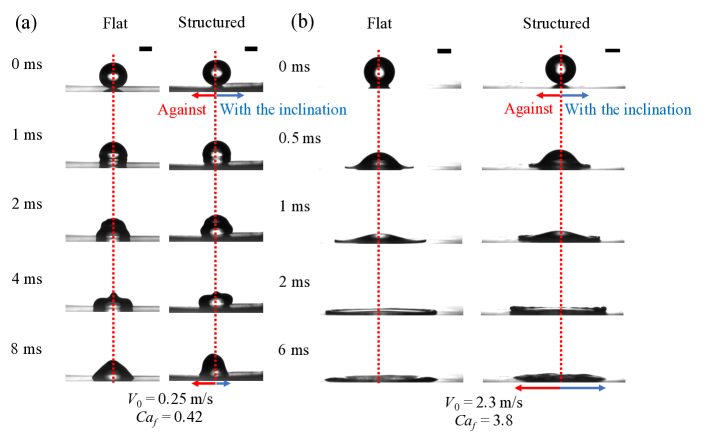
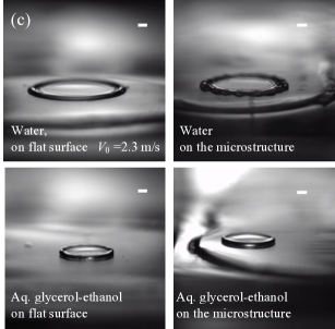
Figure 3(a) shows a series of images of a water droplet spreading after impact on the flat surfaces and asymmetrically microstructured surfaces with =0.25 m/s (). We observe that the droplet spreads not only slower on the asymmetric structures compared to the flat surface but also asymmetrically (Fig. 3a). Specifically, the spreading is faster in the direction against the inclination of the ridge than in the direction with the inclination.
Here, the numerical simulations shown in Fig. 4 reveal the spreading mechanisms on the asymmetric microstructure. In the direction against the inclination, the contact line follows along the microstructure without pinning. As a consequence, it travels a longer path compared to its flat counterpart and therefore the apparent spreading rate is slightly slower (Fig. 4a). In the direction with the inclination, the contact line spreads only on the tip of the surface ridges before it is temporarily pinned at the acute corner of the surface (1, 4 Fig. 4b). The contact angle does not reach the advancing contact angle to move down along the inclined wall and the contact line is suspended. During pinning, the liquid-air interface is stretched until it reaches the next rise of the surface (2-3, Fig. 4b). The spreading in this direction is delayed by the surface geometry compared to the flat surface if the duration of the pinning is longer than the time it would take for the interface to spread over a flat surface. Note that this mechanism is very similar to the slipping mechanism of a droplet on superhydrophobic surfaces observed experimentally with laser scanning confocal microscopy[67]. At , a slight spreading asymmetry is observed in the simulation as shown in Fig. 4(c). We also note that the simulation is carried out in an axisymmetric geometry. In the experiments, the cavity between the ridges might be filled up with the liquid phase immediately due to three-dimensional effects. The numerical model therefore only provides a qualitative picture of the asymmetric spreading.
Figure 3(b) shows snapshots of a droplet with =2.3 m/s () on flat and asymmetric surfaces. We observe symmetric spreading on the microstructured surface, indicating a small effect of microstructure geometry on liquid spreading. In this case, the impact velocity reduces the pinning time and favours the leaping mechanism (Fig. 1b).
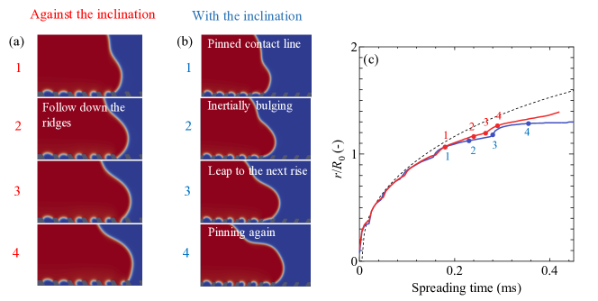
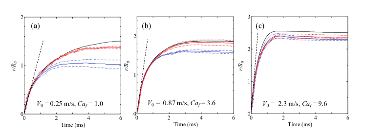
Figure 5 shows the spreading curves of droplets immediately after impact of aq. glycerol-ethanol with three different impact velocities. In all three cases in Fig. 5(a–c), the spreading curves on the flat surface and asymmetric microstructures collapse in the initial phase, until around 1 ms. The spreading velocity in this phase – estimated from the slope of the spreading curve in the initial phase – is significantly higher than the impact velocity. For example, in Fig. 5(a) it is 1 m/s, which is a factor of 4 faster than the impact velocity. The spreading in this very initial phase is fully inertial and essentially independent of the contact line friction and consequently also insensitive to the surface structures. After the initial phase, the spreading curves in the direction against and with the inclination begin to deviate from each other (Figs. 5a and b). Specifically, the spreading in the direction against the inclination (red curves) closely follows the one of the flat surface (black curves). In this direction, the small reduction in spreading velocity can be attributed to the increase of wetted area of the microsctructured surface compared to the flat surface and not to different spreading mechanisms. On the other hand, the spreading in the direction with the inclination (blue curve) is slowed down significantly. At these low impact velocities, this can be attributed to the pinning of the contact line at the acute corner of the structures.
In contrast, in Fig. 5(c), for a high impact velocity, the spreading curve in the direction with the inclination approaches the curve of the flat surface. Here, the pinning time becomes shorter and the delay by the surface structure in the direction with the inclination diminishes, as could be expected by . Consequently, the spreading is nearly symmetric on the asymmetric microstructure over the entire spreading and close to the spreading on the flat surface.
III.2 Maximum spreading radius
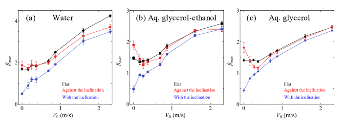
Figures 6(a–c) show the normalized maximum spreading radius, so called “spreading factor”, , with respect to the impact velocity. At low impact velocity, the maximum spreading on flat surfaces (black curves) is relatively independent from the impact velocity. This implies that the impact sequence is mainly driven by Young’s force (capillary and line friction) similar to the spontaneous spreading of a deposited droplet ( = 0). The spreading factor increases with impact velocity above m/s, as the spreading gradually becomes more dominated by the impact. On asymmetric microstructured surfaces, the spreading factor in the direction against the inclination (red curve) follows the spreading factor on the flat surface, except for the water droplet with high impact velocity (Fig. 6a). In contrast, the spreading factor in the direction with the inclination (blue curve) is smaller than the flat surface, but it approaches that of the flat surface as the impact velocity increases. The reduced pinning time with the increased impact velocity is responsible for this trend.
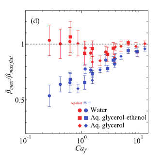
Figure 6(d) shows the spreading factor on the asymmetric microstructured surface normalized by the spreading factor on the flat surface with the same impact velocity. The horizontal axis shows the line-friction capillary number. The normalized spreading factor in the direction against the inclination is almost constant around 1. Meanwhile, the normalized spreading factor in the direction with the inclination monotonically increases from 0.5 to 1 with increasing . As a result, the asymmetry in the spreading factor decreases monotonically with increasing , while for = 0 m/s, the spreading factor in the direction against the inclination is a factor of 4 larger than in the direction with the inclination (see Fig. 6a–c). It is important to note that the conventional capillary number does not give monotonic trend (Fig. 6e). As the line friction parameter increases in proportion to the square root of liquid viscosity, more viscous fluid is likely to have higher for the same impact velocity.

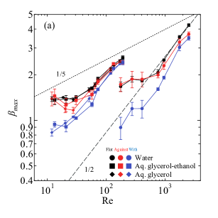
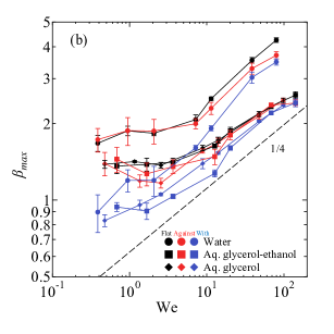
Figures 7(a) and (b) show the spreading factor with respect to Reynolds number and Weber number . The well-known relation with the Reynolds number
| (6) |
is theoretically derived assuming that the kinetic energy is solely dissipated by viscous dissipation[19, 27, 22]. Note that this is valid only in the viscous regime (i.e., for low Reynolds number). However, the spreading factors in our study do not follow Eq. 6, but , as seen in Fig. 7(a). This also agrees well with previous experimental observations of Lin et al.[27] for high Reynolds numbers. Using an energy balance analysis, Wang et al.[60] proposed the following scaling of the spreading factor,
| (7) |
where is the capillary number based on bulk viscosity. The three terms represent the contributions to the energy budget by the contact line dissipation, work done by surface tension, and viscous dissipation, respectively. Here, the first term is the leading term in Eq. 7 in our study, i.e., , and we obtain
| (8) |
Note that the exponent in Eq. 8 agrees with our experiments. For more viscous fluids, when , the classical scaling law for the viscous regime (Eq. 6) is recovered.
Meanwhile, the well-known relation between the spreading factor and Weber number is[22, 27]
| (9) |
in the capillary regime with low Ohnesorge number, while a lower exponent (1/6) is reported for viscous fluids with Oh=0.585[17, 22]. An analysis based on the momentum and mass conservation leads to Eq. 9[22]. The spreading factor in this work follows Eq. 9 well (Fig. 7b). This is in reasonable agreement with previous studies[22, 27] since Oh in this study ranges from to , which is regarded as the capillary regime. To conclude the scaling analysis, our experimental parameter space is in the capillary regime and the classical scaling law with Weber number is observed. The classical scaling with the Reynolds number (Eq.6) must be reconsidered in the capillary regime and the reasonable scaling (Eq.8) is theoretically obtained by applying the energy balance analysis by Wang et al.
The spreading factor on the microstructures for high Re (water, m/s) does not reach the value on the flat surfaces since the liquid lamella begins to break earlier on the microstructured surfaces compared to flat surfaces. As shown in Fig. 7(c), the water lamella breaks only on the microstructures but not on the flat surface. On the other hand, the lamella of aq. glycerol-ethanol is stable at = 2.3 m/s both on the flat and the microstructured surfaces. A criterion for splash is [2, 7]. For the water droplet with m/s we obtain which is slightly higher than the critical , while for the aq. glycerol-ethanol. Therefore, the instability of the water lamella in Fig. 7(c) can be understood as onset of a splash induced by the surface structure. It is responsible for the smaller spreading factor on the microstructured surface compared to the flat surface of a water droplet for high impact velocity.
In practical situations such as raindrops[68] and inkjet printing[69, 70], the impact velocity can be beyond the velocity we investigate, as high as 10 m/s for raindrops, for example. In such situations, is expected and the spreading is insensitive to the organized microstructures. This implies that the microstructures are not very effective to harness such highly inertial droplets.
IV Conclusions
Spreading of a droplet after impact on asymmetrically microstructued surfaces has been experimentally investigated. Considering the microscopic spreading mechanisms, the line-friction capillary number is proposed to distinguish between symmetric and asymmetric droplet spreading after impact. This non-dimensional number describes the ratio between capillary speed to the impact velocity. For the tilted microscale ridges considered here, the spreading in the direction against the inclination is not very sensitive to the surface structures, while the spreading in the direction with the inclination scales well with . Consequently, the asymmetry in the maximum spreading radius fades out with increasing . The scaling law for the spreading factor with Weber number () is confirmed to hold for spreading on asymmetric surfaces. However, the scaling law with Reynolds number shows larger exponent than in the classical theories () The spreading factor in our experiments follows the scaling proposed by Wang et al.[60], which takes the energy dissipation at the contact line into account in the energy balance analysis. Further work considering other surface geometries are needed to see if can be used as a general condition to distinguish between symmetric and asymmetric spreading after droplet impact.
V Acknowledgements
This work was supported by the Swedish Research Council (VR 2015-04019) and by the Swedish Foundation of Strategic research (SSF-FFL6). We would like to thank M. Do-Quang for his technical support.
References
- Dykhuizen [1994] R. C. Dykhuizen, Review of impact and solidification of molten thermal spray droplets, J. Thermal Spray Technol. 3, 351 (1994).
- Josserand and Thoroddsen [2016] C. Josserand and S. Thoroddsen, Drop impact on a solid surface, Annu. Rev. Fluid Mech. 48, 365 (2016).
- Bergeron et al. [2000] V. Bergeron, D. Bonn, J. Y. Martin, and L. Vovelle, Controlling droplet deposition with polymer additives, Nature 405, 772 (2000).
- Liu et al. [2017] M. Liu, S. Wang, and L. Jiang, Nature-inspired superwettability systems, Nat. Rev. Mater. 2, 17036 (2017).
- Attinger et al. [2000] D. Attinger, Z. Zhao, and D. Poulikakos, An Experimental Study of Molten Microdroplet Surface Deposition and Solidification: Transient Behavior and Wetting Angle Dynamics , J. Heat Transfer 122, 544 (2000).
- Minemawari et al. [2011] H. Minemawari, T. Yamada, H. Matsui, J. Y. Tsutsumi, S. Haas, R. Chiba, R. Kumai, and T. Hasegawa, Inkjet printing of single-crystal films, Nature 475, 364 (2011).
- Mundo et al. [1995] C. Mundo, M. Sommerfeld, and C. Tropea, Droplet-wall collisions: Experimental studies of the deformation and breakup process, Int. J. Multiph. Flow 21, 151 (1995).
- Xu et al. [2005] L. Xu, W. W. Zhang, and S. R. Nagel, Drop splashing on a dry smooth surface, Phys. Rev. Lett. 94, 184505 (2005).
- Josserand et al. [2005] C. Josserand, L. Lemoyne, R. Troeger, and S. Zaleski, Droplet impact on a dry surface: triggering the splash with a small obstacle, J. Fluid Mech. 524, 47–56 (2005).
- Driscoll and Nagel [2011] M. M. Driscoll and S. R. Nagel, Ultrafast interference imaging of air in splashing dynamics, Phys. Rev. Lett. 107, 154502 (2011).
- Riboux and Gordillo [2014] G. Riboux and J. M. Gordillo, Experiments of drops impacting a smooth solid surface: A model of the critical impact speed for drop splashing, Phys. Rev. Lett. 113, 024507 (2014).
- Mandre et al. [2009] S. Mandre, M. Mani, and M. P. Brenner, Precursors to splashing of liquid droplets on a solid surface, Phys. Rev. Lett. 102, 134502 (2009).
- Bouwhuis et al. [2012] W. Bouwhuis, R. C. A. van der Veen, T. Tran, D. L. Keij, K. G. Winkels, I. R. Peters, D. van der Meer, C. Sun, J. H. Snoeijer, and D. Lohse, Maximal air bubble entrainment at liquid-drop impact, Phys. Rev. Lett. 109, 264501 (2012).
- van der Veen et al. [2014] R. C. A. van der Veen, M. H. W. Hendrix, T. Tran, C. Sun, P. A. Tsai, and D. Lohse, How microstructures affect air film dynamics prior to drop impact, Soft Matter 10, 3703 (2014).
- Visser et al. [2015] C. W. Visser, P. E. Frommhold, S. Wildeman, R. Mettin, D. Lohse, and C. Sun, Dynamics of high-speed micro-drop impact: numerical simulations and experiments at frame-to-frame times below 100 ns, Soft Matter 11, 1708 (2015).
- Roisman et al. [2002] I. V. Roisman, R. Rioboo, and C. Tropea, Normal impact of a liquid drop on a dry surface: model for spreading and receding, Proc. R. Soc. Lond. A. 458, 1411 (2002).
- Attané et al. [2007] P. Attané, F. Girard, and V. Morin, An energy balance approach of the dynamics of drop impact on a solid surface, Phys. Fluids 19, 012101 (2007).
- Wildeman et al. [2016] S. Wildeman, C. W. Visser, C. Sun, and D. Lohse, On the spreading of impacting drops, J. Fluid Mech. 805, 636–655 (2016).
- Eggers et al. [2010] J. Eggers, M. A. Fontelos, C. Josserand, and S. Zaleski, Drop dynamics after impact on a solid wall: Theory and simulations, Phys. Fluids 22, 062101 (2010).
- Schroll et al. [2010] R. D. Schroll, C. Josserand, S. Zaleski, and W. W. Zhang, Impact of a viscous liquid drop, Phys. Rev. Lett. 104, 034504 (2010).
- Wang et al. [2017a] Y. Wang, M. Do-Quang, and G. Amberg, Impact of viscoelastic droplets, J. Non-newton. Fluid Mech. 243, 38 (2017a).
- Clanet et al. [2004] C. Clanet, C. Béguin, D. Richard, and D. Quéré, Maximal deformation of an impacting drop, J. Fluid Mech. 517, 199 (2004).
- Kannan and Sivakumar [2008] R. Kannan and D. Sivakumar, Drop impact process on a hydrophobic grooved surface, Colloids Surf. A Physicochem. Eng. Asp. 317, 694 (2008).
- Laan et al. [2014] N. Laan, K. G. de Bruin, D. Bartolo, C. Josserand, and D. Bonn, Maximum diameter of impacting liquid droplets, Phys. Rev. Applied 2, 044018 (2014).
- Lee et al. [2016a] J. B. Lee, D. Derome, R. Guyer, and J. Carmeliet, Modeling the maximum spreading of liquid droplets impacting wetting and nonwetting surfaces, Langmuir 32, 1299 (2016a).
- Lee et al. [2016b] J. B. Lee, N. Laan, K. G. de Bruin, G. Skantzaris, N. Shahidzadeh, D. Derome, J. Carmeliet, and D. Bonn, Universal rescaling of drop impact on smooth and rough surfaces, J. Fluid Mech. 786, R4 (2016b).
- Lin et al. [2018] S. Lin, B. Zhao, S. Zou, J. Guo, Z. Wei, and L. Chen, Impact of viscous droplets on different wettable surfaces: Impact phenomena, the maximum spreading factor, spreading time and post-impact oscillation, J. Colloid Interface Sci. 516, 86 (2018).
- Yarin [2006] A. Yarin, Drop impact dynamics: Splashing, spreading, receding, bouncing…, Annu. Rev. Fluid Mech. 38, 159 (2006).
- Xu [2007] L. Xu, Liquid drop splashing on smooth, rough, and textured surfaces, Phys. Rev. E 75, 056316 (2007).
- Robson and Willmott [2016] S. Robson and G. R. Willmott, Asymmetries in the spread of drops impacting on hydrophobic micropillar arrays, Soft Matter 12, 4853 (2016).
- Tran et al. [2013] T. Tran, H. J. J. Staat, A. Susarrey-Arce, T. C. Foertsch, A. van Houselt, H. J. G. E. Gardeniers, A. Prosperetti, D. Lohse, and C. Sun, Droplet impact on superheated micro-structured surfaces, Soft Matter 9, 3272 (2013).
- Tsai et al. [2009] P. Tsai, S. Pacheco, C. Pirat, L. Lefferts, and D. Lohse, Drop impact upon micro- and nanostructured superhydrophobic surfaces, Langmuir 25, 12293 (2009).
- Gauthier et al. [2015] A. Gauthier, S. Symon, C. Clanet, and D. Quéré, Water impacting on superhydrophobic macrotextures, Nat. Commun. 6, 8001 (2015).
- Bartolo et al. [2006] D. Bartolo, F. Bouamrirene, É. Verneuil, A. Buguin, P. Silberzan, and S. Moulinet, Bouncing or sticky droplets: Impalement transitions on superhydrophobic micropatterned surfaces, EPL 74, 299 (2006).
- Guémas et al. [2012] M. Guémas, A. G. Marín, and D. Lohse, Drop impact experiments of non-newtonian liquids on micro-structured surfaces, Soft Matter 8, 10725 (2012).
- Vaikuntanathan and Sivakumar [2016] V. Vaikuntanathan and D. Sivakumar, Maximum spreading of liquid drops impacting on groove-textured surfaces: Effect of surface texture, Langmuir 32, 2399 (2016).
- Chen et al. [2016] H. Chen, P. Zhang, L. Zhang, H. Liu, Y. Jiang, D. Zhang, Z. Han, and L. Jiang, Continuous directional water transport on the peristome surface of Nepenthes alata, Nature 532, 85 (2016).
- Bohn and Federle [2004] H. F. Bohn and W. Federle, Insect aquaplaning: Nepenthes pitcher plants capture prey with the peristome, a fully wettable water-lubricated anisotropic surface, Proc. Natl. Acad. Sci. U.S.A. 101, 14138 (2004).
- Bauer et al. [2008] U. Bauer, H. F. Bohn, and W. Federle, Harmless nectar source or deadly trap: Nepenthes pitchers are activated by rain, condensation and nectar, Proc. Royal Soc. B 275, 259 (2008).
- Yu et al. [2018] C. Yu, C. Li, C. Gao, Z. Dong, L. Wu, and L. Jiang, Time-dependent liquid transport on a biomimetic topological surface, ACS Nano 12, 5149 (2018).
- Li et al. [2016] C. Li, N. Li, X. Zhang, Z. Dong, H. Chen, and L. Jiang, Uni-Directional Transportation on Peristome-Mimetic Surfaces for Completely Wetting Liquids, Angew. Chem. Int. Ed. 55, 14988 (2016).
- de Gennes [1985] P. G. de Gennes, Wetting: statics and dynamics, Rev. Mod. Phys. 57, 827 (1985).
- Barrat and Bocquet [1999] J.-L. Barrat and L. Bocquet, Influence of wetting properties on hydrodynamic boundary conditions at a fluid/solid interface, Faraday Discuss. 112, 119 (1999).
- Blake and Haynes [1969] T. Blake and J. Haynes, Kinetics of liquidliquid displacement, J. Colloid Interface Sci. 30, 421 (1969).
- Blake [2006] T. D. Blake, The physics of moving wetting lines, J. Colloid Interface Sci. 299, 1 (2006).
- Bonn et al. [2009] D. Bonn, J. Eggers, J. Indekeu, J. Meunier, and E. Rolley, Wetting and spreading, Rev. Mod. Phys. 81, 739 (2009).
- Snoeijer and Andreotti [2013] J. H. Snoeijer and B. Andreotti, Moving Contact Lines: Scales, Regimes, and Dynamical Transitions, Annu. Rev. Fluid Mech. 45, 269 (2013).
- Weiland and H [1981] R. H. Weiland and D. S. H, Moving contact lines and rivulet instabilities. Part 2. Long waves on flat rivulets, J. Fluid Mech. 107, 261 (1981).
- Yue and Feng [2011a] P. Yue and J. J. Feng, Wall energy relaxation in the cahn-hilliard model for moving contact lines, Phys. Fluids 23, 012106 (2011a).
- Duvivier et al. [2011] D. Duvivier, D. Seveno, R. Rioboo, T. D. Blake, and J. De Coninck, Experimental evidence of the role of viscosity in the molecular kinetic theory of dynamic wetting, Langmuir 27, 13015 (2011).
- Vo and Tran [2018] Q. Vo and T. Tran, Contact line friction of electrowetting actuated viscous droplets, Phys. Rev. E 97, 063101 (2018).
- Hong et al. [2014] J. Hong, Y. K. Kim, K. H. Kang, J. Kim, and S. J. Lee, Spreading dynamics and oil film entrapment of sessile drops submerged in oil driven by dc electrowetting, Sens. Actuators B Chem. 196, 292 (2014).
- Carlson et al. [2012] A. Carlson, G. Bellani, and G. Amberg, Universality in dynamic wetting dominated by contact-line friction, Phys. Rev. E 85, 045302(R) (2012).
- Lee et al. [2019] Y. Lee, N. Matsushima, S. Yada, S. Nita, T. Kodama, G. Amberg, and J. Shiomi, Revealing How Topography of Surface Microstructures Alters Capillary Spreading, Sci. Rep. 9, 7787 (2019).
- Xia and Steen [2018] Y. Xia and P. H. Steen, Moving contact-line mobility measured, J. Fluid Mech. 841, 767 (2018).
- Xia and Steen [2020] Y. Xia and P. H. Steen, Dissipation of oscillatory contact lines using mode scanning, npj Microgravity 6, 3 (2020).
- Do-Quang et al. [2015] M. Do-Quang, J. Shiomi, and G. Amberg, When and how surface structure determines the dynamics of partial wetting, Eur. Phys. Lett. 110, 46002 (2015).
- Wang et al. [2015] J. Wang, M. Do-Quang, J. J. Cannon, F. Yue, Y. Suzuki, G. Amberg, and J. Shiomi, Surface structure determines dynamic wetting, Sci. Rep. 5, 8474 (2015).
- Yada et al. [2019] S. Yada, S. Bagheri, J. Hansson, M. Do-Quang, F. Lundell, W. van der Wijngaart, and G. Amberg, Droplet leaping governs microstructured surface wetting, Soft Matter 15, 9528 (2019).
- Wang et al. [2017b] Y. Wang, G. Amberg, and A. Carlson, Local dissipation limits the dynamics of impacting droplets on smooth and rough substrates, Phys. Rev. Fluids 2, 033602 (2017b).
- Carlborg et al. [2011] C. F. Carlborg, T. Haraldsson, K. Öberg, M. Malkoch, and W. van der Wijngaart, Beyond pdms: off-stoichiometry thiol–ene (oste) based soft lithography for rapid prototyping of microfluidic devices, Lab Chip 11, 3136 (2011).
- Eral et al. [2013] H. B. Eral, D. J. C. M. ’t Mannetje, and J. M. Oh, Contact angle hysteresis: a review of fundamentals and applications, Colloid Polym. Sci. 291, 247 (2013).
- Amberg et al. [1999] G. Amberg, R. Tönhardt, and C. Winkler, Finite element simulations using symbolic computing, Math. Comp Simul. 49, 257 (1999).
- Jacqmin [2000] D. Jacqmin, Contact-line dynamics of a diffuse fluid interface, J. Fluid Mech. 402, 57–88 (2000).
- Yue and Feng [2011b] P. Yue and J. J. Feng, Wall energy relaxation in the cahn–hilliard model for moving contact lines, Phys. Fluids 23, 012106 (2011b).
- Yue et al. [2010] P. Yue, C. Zhou, and J. J. Feng, Sharp-interface limit of the cahn–hilliard model for moving contact lines, J. Fluid Mech. 645, 279–294 (2010).
- Schellenberger et al. [2016] F. Schellenberger, N. Encinas, D. Vollmer, and H.-J. Butt, How water advances on superhydrophobic surfaces, Phys. Rev. Lett. 116, 096101 (2016).
- Gossard et al. [1992] E. E. Gossard, R. G. Strauch, D. C. Welsh, and S. Y. Matrosov, Cloud Layers, Particle Identification, and Rain-Rate Profiles from ZRVf Measurements by Clear-Air Doppler Radars, J. Atmos. Oceanic Technol. 9, 108 (1992).
- Sen and Darabi [2007] A. K. Sen and J. Darabi, Droplet ejection performance of a monolithic thermal inkjet print head, J. Micromech. Microeng. 17, 1420 (2007).
- Negro et al. [2018] A. Negro, T. Cherbuin, and M. P. Lutolf, 3D Inkjet Printing of Complex, Cell-Laden Hydrogel Structures, Sci. Rep. 8, 17099 (2018).