Two-dimensional thermal finite element model of directed energy deposition:
matching melt pool temperature profile with pyrometer measurement
Abstract
An open source two-dimensional (2D) thermal finite element (FE) model of the Directed Energy Deposition (DED) process is developed using the Python-based FEniCS framework. The model incrementally deposits material ahead of the laser focus point according to the geometry of the part. The laser heat energy is supplied by a Gaussian-distributed heat source while the phase change is represented by increased heat capacity around the solidus-liquidus temperature range. Experimental validation of the numerical model is performed by matching with the melt pool temperature measurements taken by a dual wavelength pyrometer during the build process of a box-shaped Ti-6Al-4V part with large geometrical voids. Effects of large geometrical voids on the melt pool shape and maximum melt pool temperature are examined. Both the numerical and experimental data show an increase in the melt pool size and temperature during deposition above large voids. The trailing edge of the melt pool’s temperature profile obtained using the developed numerical model closely matches pyrometer measurements.
keywords:
additive manufacturing , directed energy deposition , melt pool temperature , pyrometer , large geometrical voids , finite element1 Introduction
Additive manufacturing (AM) is a flexible technology allowing incremental production of components with complex geometries from a wide range of materials. The growth in application of this technology accelerated in recent years, attracting attention of both industry and academic research [1, 2, 3, 4, 5, 6, 7, 8]. Compared to traditional formative and subtractive manufacturing methods, AM exhibits shorter production times. AM can directly follow Computer Aided Design (CAD) model of the part and build a near net shape product. Applications of AM technology include cladding, tool repair, and a production of functionally graded materials.
Feedstock material for AM of metallic parts assumes the form of a wire or a powder. Melting and bonding of the feedstock is performed by a moving heat source, which can be an electron beam or a laser. Two common powder-based AM techniques are Powder Bed Fusion (PBF) and Directed Energy Deposition (DED). In PBF, a full layer of powder is spread on a build platform, followed by melting/sintering of a chosen portion of the surface layer to form the part. The platform is then lowered, a full layer of powder is spread and selectively melted, forming a new layer of the part being built. In laser based DED, the powder is blown through nozzles into the laser beam focus point on the build surface. The nozzles and the laser source are mounted on the deposition head which moves according to a preprogrammed deposition path. Both PBF and DED AM processes are characterized by phenomenally rich thermal history because localized cyclical heating produces high thermal gradients, fast heating/cooling rates, and multiple melting/solidification cycles.
Complex thermal history of additively manufactured parts, especially those made of metallic alloys with microstructure depending on melting and solidification rates, results in strong and difficult-to-predict dependencies of the product quality on manufacturing process parameters [9, 10, 11, 12, 13]. Uncertainties in quality prevent wider AM deployment. Thermal history depends on the parameters of the build process, which are laser power, deposition path, part geometry and dimensions, initial and build environment conditions. Suboptimal or non-uniform thermal histories produce more defects, such as heterogeneous microstructure [14, 11, 15], porosity [16, 17, 18, 19], and residual stresses [20, 21, 10, 22], leading to part distortion and degradation of mechanical properties. Components produced via DED commonly require post-manufacturing processes (e.g., machining or hot isostatic pressing) to account for the presence of process induced defects.
The ability to predict and control thermal history in AM would have a significant impact on improving the as-built part and reducing cost. Two- and three-dimensional finite element (FE) based numerical modeling of the directed energy deposition of Ti-6Al-4V parts have been subject to multiple research efforts [23, 24, 25, 26, 27]. Denlinger et al. [24] and Heigel et al. [26] developed and validated a thermo-mechanical model of electron beam and laser deposition of a thin Ti-6Al-4V wall using FE solver as implemented in CUBIC (PAN Computing, LLC [28]). Similarly to the work presented here, several studies examined the details of the melt pool profile during the Ti-6Al-4V deposition. The temperature profile and melt pool depth in laser powder bed fusion of Ti-6Al-4V was analyzed using a finite difference method as implemented in Matlab® [29] by Criales and Özel [30]. Cheng et al. [31] used Abaqus [32] software with custom DFLUX subroutine implementing a volumetric heat source to examine the temperature profile and melt pool size during Ti-6Al-4V electron beam additive manufacturing (EBAM) process. Peyre et al. [33] and de La Batut et al. [34] compared experimental, analytical, and numerical predictions of a temperature field during direct metal deposition of Ti-6Al-4V with their numerical models implemented in COMSOL Multiphysics® [35]. Vincent et al. [36] implemented thermal-fluid numerical simulation using the simpleFOAM solver of the OPenFOAM suite [37] to predict melt pool width and height for a single straight track deposition on a flat surface. The prediction was achieved by iterative optimization of analytically defined track geometry with the width and height of the melt pool assumed equal to the width and height of the track while the track cross-section shape was approximated by a circular segment. Simulations show a good agreement with experiment with the largest relative error of 21.4% in the track height for a steady state of the deposition on a homogeneous flat substrate. Lu et al. [38] used an in-house research software COupled MEchanical and Thermal (COMET) [39, 40] to characterize residual stress and distortion in rectangular and S-shaped Ti-6Al-4V parts built using DED. The largest average temperature error at all thermocouple locations was lower than 13%. Recently, a fast semi-analytical thermal model of DED process including phase change and gas flow effects was developed by Weisz-Patrault [41] using Scilab [42]. The model, applicable to single-track builds with geometries that do not vary in vertical direction, was compared with pyrometer measurement at two part locations achieving a good agreement with only 2.6% average error. As seen, the simulations of the DED process were performed using commercial software, while some used in-house research codes.
This work introduces an open source two-dimensional (2D) FE numerical model of heat transfer during the DED process developed within an open-source FEniCS [43] framework. Python source code implementing the numerical model and resulting animations are available at GitLab under LGPL-3.0 license. Unlike the bulk of published work addressing PBF, this work investigates DED process, specifically Laser Engineered Net Shaping (LENS®, Optomec). The PBF additive manufacturing process spreads a full layer of new powder in one step. Selected portions of the full layer are melted only after the complete layer is spread. The PBF melt pool is not constantly exposed to cold, freshly deposited material. Contrary to PBF, the DED process continuously deposits cold material directly into the melt pool. The model of the LENS DED process therefore needs to implement incremental material deposition. Modeling of incremental DED process comes with intense numerical challenges. First is the convergence issue due to thermal gradients arising from the cold material being continuously deposited into the melt. Aside from convergence issues, incremental deposition requires continuous adding of new elements, modifying boundary conditions, and rebuilding the system of equations repeatedly during the deposition of a single line. While the finite element model of PBF rebuilds the system of equations only once per each deposited layer, the incremental deposition implemented in this work performed 1580 rebuilds of the system of equations during the deposition of a single layer. High computational demands and the divergence of Newton solver’s iterations caused by the cold material being deposited directly into the melt pool are the main challenges addressed in the newly developed FEA DED model, affording a detailed look at the melt pool temperature profile.
The earlier works do not examine details of the melt pool temperature profile. Further, they do not look at the variation of the melt pool temperature profile above large geometrical voids. The newly developed thermal model of incremental DED process is applied to examine the temperature distribution during direct laser deposition of a Ti-6Al-4V alloy part with the presence of large geometrical voids. For this study, a 2D model was used in lieu of a 3D model because of the increased computational efficiency, ease of mesh refinement around the voids, and the ability to readily change the void’s size and location. A rectangular prism shaped part with a geometry incorporating large voids was designed and then built using the Laser Engineered Net Shaping (LENS®), which is a popular flavor of DED developed at Sandia National Laboratories in the 1990s [44]. The melt pool temperature during the build process was monitored by a dual wavelength pyrometer as described in [45]. The finite element model was then constructed and correlated with temperature distribution from the build experiment.
2 Part geometry and the deposition process
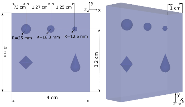
The geometry of the part examined in this study is shown in Figure 1. The dimensions of the complete block are 4 cm (width, along -direction) 4 cm (height, along -direction) 1 cm (depth, along -direction). Spherical voids were located along the lateral mid-section of the part, with centers at the distances 0.73 cm, 2.0 cm, and 3.25 cm from the left edge, and 3.2 cm from the bottom edge. Additionally, diamond and tear-drop shaped voids were part of the build experiment but not included in simulations. The radii of the spherical voids were 0.25 cm, 0.183 cm, and 0.125 cm.
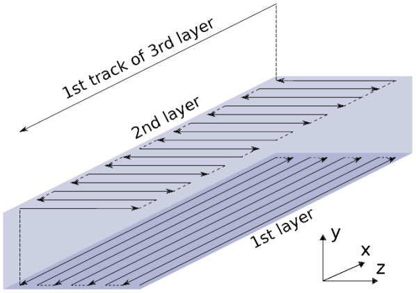
The part was built by depositing 79 layers of Ti-6Al-4V powder. The direction of deposition was rotated by 90 degrees for each successive layer. Odd layers were formed by 19 tracks deposited along the -direction. Even layers were formed by tracks deposited in the -direction. The 2D numerical model was compared with the deposition of the 10th track of the 69th layer, chosen as a center line of 19 tracks of the layer 69.
3 Numerical representation
3.1 FEniCS framework
Open source finite element suite FEniCS [46] was used to build a numerical heat transfer model of the DED process. The FEniCS framework [43] consists of a collection of interoperable software components, including Dynamic Object-oriented Library for FINite element computation DOLFIN [47, 48], FEniCS Form Compiler FFC [49], FInite element Automatic Tabulator FIAT [50, 51], inlining module Instant built on top of Simplified Wrapper and Interface Generator SWIG [52] and Python package distutils [53], Unified Form-assembly Code UFC [54, 55], Unified Form Language UFL [56], and a mesh generation component mshr utilizing tetrahedral mesh generator TETGEN [57] and Computational Geometry Algorithms Library CGAL [58] as mesh generation backends.
3.2 Heat transfer model
Heat transfer is governed by the heat equation
| (1) |
where is the density, is the temperature, is the time, and is the thermal conductivity. The specific heat was increased for the temperature range between solidus and liquidus to account for the latent heat of melting as follows

| (2) |
The temperatures , , and the increment of specific heat are defined as
| (3) |
The temperature dependence of (Equation 2) is illustrated in Figure 3. The triangle-shaped continuous function improved the stability of the FE solver in comparison with a step function alternative deployed by Piekarska et al. [59].
| Material Parameter | Symb. | Value | Units | Process Parameter | Symb. | Value | Units |
|---|---|---|---|---|---|---|---|
| Thermal conductivity | 7.2 | W/m/K | Laser power | 300 | W | ||
| Specific heat of solid | 560 | J/kg/K | Laser power abs. coef. | * | - | ||
| Latent heat | J/kg | Laser beam width | m | ||||
| Density of material | 4420 | kg/m3 | Layer thickness | m | |||
| Thermal emissivity | 0.54 | - | Deposition velocity | m/s | |||
| Convective heat transfer coef. | 30 | W/m2/K | Initial/bottom temperature | 127, 30, 427* | °C | ||
| Solidus-liquidus range | 16001650 | °C | External temperature | 30 | °C |
-
*
As described in Section 4.2, in cases 1 and 2, and in case 3, while °C in case 1, °C in case 2, and °C in case 3
3.3 Boundary conditions
On the bottom boundary ( cm), the temperature is kept constant
| (4) |
On the left ( cm) and right ( cm) boundaries, and on the surface of voids, a convection boundary condition is imposed
| (5) |
where is the convective heat transfer coefficient. On the top boundary, the heat supplied by the laser, , as well as heat release by convection and radiation are assumed
| (6) |
where is the Stefan-Boltzmann constant Wm-2K and is the thermal emissivity of Ti-6Al-4V. The heat supplied by the laser is represented by a Gaussian heat source [60]
| (7) |
where
| (8) |
is the magnitude of the power distribution function, is the effective heat absorption coefficient for laser power , is the displacement of the laser focus point, and is the laser beam width. Because is the magnitude of the 1D Gaussian function (Equation 7) and the total laser power is distributed over the 2D surface, Equations 7 and 8 are chosen to represent a section of 2D Gaussian distribution with the coordinate . The DED process parameters and calibrated effective laser absorption coefficient are presented in Table 1. Other 2D models [14, 23] calibrate the 1D magnitude instead of without listing its value. The calibration of in the present study provides more physical information. The Ti-6Al-4V material properties and the deposition process parameters are listed in Table 1.
3.4 Model of the deposition process
The new material at temperature is deposited at distance ahead of the laser beam focus point to assure the stability of Newton’s FE solver. A single column of material with temperature is deposited at a time. The time intervals between depositions of successive columns correspond to the laser velocity as listed in Table 1.
3.5 Finite element mesh
The triangular FE mesh with linear elements used in this work was constructed using the mshr module of FEniCS. The mesh was refined within three layers of the simulated deposition process (Section 4.2) as well as on the edge of the voids. The largest and the most frequent mesh element within the deposited layers was a right triangle with two sides of 25.4 m. This refinement accommodated the laser beam width of 500 m and also allowed material deposition increments of 25.4 m. Each of the deposited layers was split into a grid of 1580 columns and 20 rows for deposition purposes. A complete column at the leading edge of the layer was deposited in each deposition step, resulting in a deposition layer with a thickness of 508 m. Twice-coarser mesh refinement was applied within the layer under the three deposited layers to accommodate the heating pass. The total number of elements in each simulation was 206,012, with a total of 104,212 vertices. The mesh minimum cell radius ratio, defined as the ratio of inscribed to circumscribed radii times two [61], was 0.09. The mesh within the topmost portion of the part can be seen in Figure 5. The time step utilized for these FE simulations was 0.33 ms.
4 Pyrometer data versus simulations
4.1 Pyrometer data
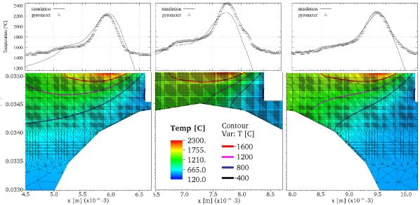
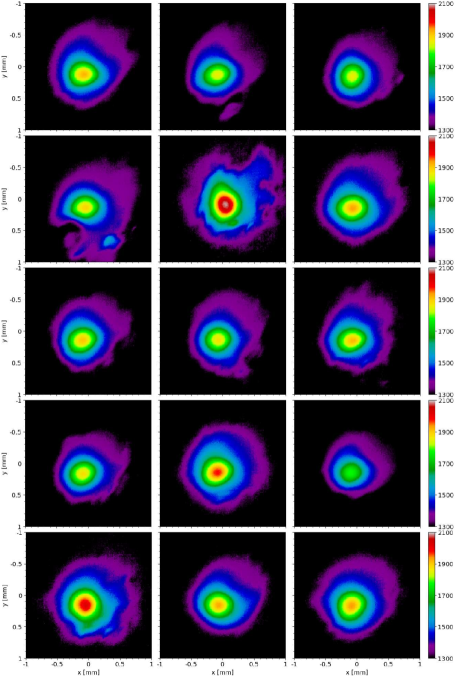
The present numerical model was calibrated and validated by examining the effects of large geometrical voids on the melt pool size and temperature distribution during the deposition of a part (Figure 1). Pyrometer measurements (Figure 7) of the melt pool temperature were taken during deposition of the center line of layer 69, which is located just above the largest spherical void. Each pyrometer scan produced an array of 752 480 temperature values with a grid distance of 12.8 m. Melt pool traveled diagonally at 225° angle w.r.t. -direction in Figure 7. Average location of the melt pool center was first obtained as the average point of highest temperature among the scans in Figure 7. Temperature profiles along 190 points of 45° line section of each scan passing through the melt pool center were then compared with simulations in Figure 6. 150 leading edge and 140 trailing edge points of each temperature profile were cut out as temperatures further from melt pool center were out of pyrometer temperature calibration range. Similarly, only central portion of pyrometer scans is shown in Figure 7. Spatial placement of the pyrometer temperature profiles in Figure 6 was set according to pyrometer timestamps and deposition velocity. Profiles are spaced irregularly because of variability in the pyrometer sampling rate. The first and last snapshots of the layer extend slightly out of build surface due to laser acceleration and deceleration.
4.2 Simulations
Accurate simulations of the direct laser deposition process face several challenges:
-
•
A wide range of phenomena are involved: heat conduction, convection, absorption of electromagnetic energy, and phase change. Each of these phenomena needs to be approximated by a numerical model and parameterized, and parameters are temperature dependent [62].
-
•
The meshing process, required by FE method, is non-trivial for an arbitrary complex domain [63]. The presence of a large temperature gradient demands a fine mesh, especially with narrow beam radius. A high cooling rate requires a short time step. Therefore, meshing and calculations, especially for 3D domains, are computationally demanding.
Material parameters in the present simulations (Table 1) were assumed to be temperature independent, aiming to reproduce temperature profile above voids with minimal set of parameters. Two parameters were calibrated to match melt pool length and maximum melt pool temperature to pyrometer measurements: the effective laser power absorption coefficient and the initial temperature of the build . The melt pool length was deduced from the length of the plateau region extending horizontally from the solidus temperature at the trailing edge of the temperature profile [64, 31, 65, 66, 67].
Four laser passes were performed in each simulation. Each simulation began with a single bare-laser heating pass followed by a deposition of three layers. The heating pass aimed to achieve temperature distribution similar to the fully continuous build process which was used to obtain pyrometer measurements. The first deposited layer included the top-most portion of the largest void. The bottom boundary of the second deposited layer is located just above the top surface of the largest void. The third layer is deposited on the top of the second layer.
Three cases were simulated to examine the effects of direction of deposition and laser power. The calculated melt pool surface temperatures from these three simulations are presented along with pyrometer measurements in Figure 6. Solid lines show simulated results: the blue line shows temperature during deposition of the first layer, the black line during deposition of the second layer, and the red line during the deposition of the third layer.
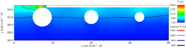
In the first case, with results shown in the first and fourth plots in Figure 6, the initial heating pass and successive deposition of three layers were all performed from left to right. Initial temperature of the build surface was set to 127 °C after a few trial-and-error adjustments in 50 °C steps to fit the measured melt pool width, while the laser power absorption coefficient was set to to fit the maximum melt pool temperature. Mesh configuration and calculated temperature of the upper portion of the part during deposition of the second layer are shown in Figure 5. As seen in Figure 5, the simulated melt pool depth is smaller than the thickness of the deposited layer. In simulations, new material is deposited in narrow columns forming a continuous layer that does not fully melt. This observation is consistent with powder particles being partially sintered instead of fully melted [68].
In the second case, shown in the second and fifth plots in Figure 6, the simulation began with a single heating pass from right to left, followed by a deposition of three layers in alternating directions. That is, the first layer was deposited left to right, the second right to left, and the third left to right. The temperature of the build surface was initialized at °C. A pause of 240 ms between depositions of successive layers was introduced in simulations to compensate for the successive layers being deposited in alternate directions. The pause is needed to avoid excessive temperature when starting to deposit a new layer on the top of recently deposited material. Simulation results from the deposition of the third layer in the second case (red line in the second plot in Figure 6) were found to be the best match to the measured data because measurements were taken when successive tracks were deposited in alternating directions (Fig. 2).
For the first two cases, the pyrometer data in Figure 6 was scaled up by a multiplicative factor of 1.18. This adjustment displaced the solidification plateau from pyrometer data closer to the plateau from simulations, which is just above the solidus temperature. The need for this adjustment can be attributed to the present numerical model not accounting for the flow of inert gas which cools down the build surface, or inaccuracy of the pyrometer. Moreover, the 2D model does not allow lateral heat dissipation perpendicular to the direction of deposition, what results in overestimation of melt pool temperature.
In the third case, shown in the third and sixth plots in Figure 6, pyrometer data were not scaled up. The direction of deposition alternated with pauses as in the second case, however the laser power absorption coefficient was cut by 25% to match 1.18 lower maximum melt pool temperature. The initial temperature of the build surface was increased to °C to match the melt pool length.
The blue solid lines in Figure 6 demonstrate very high temperature during the deposition in the region including top portion of the large void. This is mainly due to a small amount of cold material being added with heat supply at the same level as when the large amount of material is added. In experimental setup, the deposition in this region would experience distortions with largely unknown consequences for temperature measurements. The deposition of the layer including top portion of the large void is therefore not considered for comparison with measured temperature. Instead, simulated results from the deposition of two lines above the large void are compared with the temperature measured during the deposition of the center line above the large void.
The experiment was done on a 1 cm thick wall, and the top of each cavity only spanned one to three line passes in general. This would be about 0.5 mm to 1.5 mm. Since there would be at least 4 mm on each side of the cavity that was fully supported, and the cavities were spherical, we made the assumption that there was enough supporting material and structure to reduce most of the distortion that would be seen on the layer just above the cavity. Thus we did not assume distortion would have an effect on the melt pool temperature when depositing these lines. However, distortion and residual stress effects are something we are still looking into with current and upcoming studies.
5 Conclusions
Direct laser deposition of a narrow overhang layer, as the thin layer above a large round void presented in this work, is a challenge for additive manufacturing due to insufficient support of newly deposited material. The two-dimensional model of the temperature evolution during direct laser deposition developed in this work was applied to examine the melt pool size and temperature during the build process above large geometrical voids. Trailing edge of the longitudinal section of the temperature profile across the melt pool exhibited a plateau region extending horizontally from near-solidus temperature. The numerical model was calibrated by matching the length of solidification plateau between the simulation and pyrometer data. Implications of the study are:
-
•
A 2D model can provide a reasonable approximation of the central longitudinal section of the melt pool temperature profile.
-
•
The solidification plateau in the melt pool temperature profile increases in length when depositing material above large void.
-
•
The portion of the part above large voids cools down slower. It remains at the temperature higher than the regions without underlying voids. The effect is more pronounced with larger voids.
-
•
The maximum temperature of the melt pool increases during deposition above a large void. A smaller increase of maximum melt pool temperature was observed above small voids.
-
•
Deposition in alternate directions leads to increased maximum melt pool temperatures at the time when the direction of deposition is reversed. A pause between the deposition of successive layers helps to mitigate this effect. Deposition in a single direction leads to more uniform maximum melt pool temperatures.
-
•
Melt pool length, as characterized by extent of the solidification plateau in the melt pool temperature profile, correlates strongly with temperature of build surface, while the maximum melt pool temperature correlates with power of the heat source.
The present 2D FE model of the DED process can, upon calibration, closely reproduce the melt pool shape during the deposition of geometrically complex parts. The two calibrated parameters are the effective heat absorption coefficient for laser power and initial temperature of the build surface. With serial computational time in the order of tens of hours, this model can estimate effects of process parameters on the melt pool temperature profile. Aiming at minimal complexity needed to reproduce the measured melt pool temperature variation, the model is amendable to improvements. Changes as making material properties temperature-dependent and weighting the thermal properties by the phase fractions instead of using average properties are expected to improve physical representation and are in plans for the future work. Relying on the aid of parallel implementation, which is already partially supported by FEniCS framework, the model can be extended to realistic-scale 3D DED process simulations.
Acknowledgment
Research was sponsored by the Army Research Laboratory and was accomplished under Cooperative Agreement Number W911NF-15-2-0025. The views and conclusions contained in this document are those of the authors and should not be interpreted as representing the official policies, either expressed or implied, of the Army Research Laboratory or the U.S. Government. The U.S. Government is authorized to reproduce and distribute reprints for Government purposes notwithstanding any copyright notation herein.
References
- Kruth et al. [1998] J.-P. Kruth, M. C. Leu, T. Nakagawa, Progress in Additive Manufacturing and Rapid Prototyping, CIRP Annals 47 (1998) 525–540.
- ASTM International [2010] ASTM International, Standard terminology for additive manufacturing technologies, ASTM-Standards (2010) 13–15.
- Guo and Leu [2013] N. Guo, M. C. Leu, Additive manufacturing: technology, applications and research needs, Frontiers of Mechanical Engineering 8 (2013) 215–243.
- Mellor et al. [2014] S. Mellor, L. Hao, D. Zhang, Additive manufacturing: A framework for implementation, International Journal of Production Economics 149 (2014) 194–201.
- Frazier [2014] W. E. Frazier, Metal additive manufacturing: A review, Journal of Materials Engineering and Performance 23 (2014) 1917–1928.
- Rubenchik et al. [2018] A. M. Rubenchik, W. E. King, S. S. Wu, Scaling laws for the additive manufacturing, Journal of Materials Processing Technology 257 (2018) 234–243.
- Ngo et al. [2018] T. D. Ngo, A. Kashani, G. Imbalzano, K. T. Q. Nguyen, D. Hui, Additive manufacturing (3D printing): A review of materials, methods, applications and challenges, Composites Part B: Engineering 143 (2018) 172–196.
- Loh et al. [2018] G. H. Loh, E. Pei, D. Harrison, M. D. Monzón, An overview of functionally graded additive manufacturing, Additive Manufacturing 23 (2018) 34–44.
- Gu et al. [2012] D. D. Gu, W. Meiners, K. Wissenbach, R. Poprawe, Laser additive manufacturing of metallic components: materials, processes and mechanisms, International Materials Reviews 57 (2012) 133–164.
- Thompson et al. [2015] S. M. Thompson, L. Bian, N. Shamsaei, A. Yadollahi, An overview of Direct Laser Deposition for additive manufacturing; Part I: Transport phenomena, modeling and diagnostics, Additive Manufacturing 8 (2015) 36–62.
- Bian et al. [2015] L. Bian, S. M. Thompson, N. Shamsaei, Mechanical Properties and Microstructural Features of Direct Laser-Deposited Ti-6Al-4V, JOM 67 (2015) 629–638.
- Seifi et al. [2016] M. Seifi, A. Salem, J. Beuth, O. Harrysson, J. J. Lewandowski, Overview of materials qualification needs for metal additive manufacturing, JOM 68 (2016) 747–764.
- Thompson et al. [2016] M. K. Thompson, G. Moroni, T. Vaneker, G. Fadel, R. I. Campbell, I. Gibson, A. Bernard, J. Schulz, P. Graf, B. Ahuja, F. Martina, Design for Additive Manufacturing: Trends, opportunities, considerations, and constraints, CIRP Annals 65 (2016) 737–760.
- Wang and Felicelli [2006] L. Wang, S. Felicelli, Analysis of thermal phenomena in LENSTM deposition, Materials Science and Engineering: A 435–436 (2006) 625–631.
- Hernández-Nava et al. [2016] E. Hernández-Nava, C. Smith, F. Derguti, S. Tammas-Williams, F. Leonard, P. Withers, I. Todd, R. Goodall, The effect of defects on the mechanical response of Ti-6Al-4V cubic lattice structures fabricated by electron beam melting, Acta Materialia 108 (2016) 279–292.
- Kobryn and Semiatin [2001] P. A. Kobryn, S. L. Semiatin, Mechanical properties of laser-deposited Ti-6Al-4V, in: Solid Freeform Fabrication Proceedings, Austin, pp. 6–8.
- Galarraga et al. [2016] H. Galarraga, D. A. Lados, R. R. Dehoff, M. M. Kirka, P. Nandwana, Effects of the microstructure and porosity on properties of Ti-6Al-4V ELI alloy fabricated by electron beam melting (EBM), Additive Manufacturing 10 (2016) 47–57.
- Wang et al. [2009] L. Wang, P. Pratt, S. Felicelli, H. El Kadiri, J. Berry, P. Wang, M. Horstemeyer, Experimental analysis of porosity formation in laser-assisted powder deposition process, in: 2009 TMS Annual Meeting & Exhibition, pp. 389–396.
- Liu et al. [2015] S. Liu, Q. Li, W. Chen, L. Tong, G. Cheng, An identification method for enclosed voids restriction in manufacturability design for additive manufacturing structures, Frontiers of Mechanical Engineering 10 (2015) 126–137.
- Rangaswamy et al. [2005] P. Rangaswamy, M. L. Griffith, M. B. Prime, T. M. Holden, R. B. Rogge, J. M. Edwards, R. J. Sebring, Residual stresses in LENS® components using neutron diffraction and contour method, Materials Science and Engineering: A 399 (2005) 72–83.
- Zheng et al. [2008] B. Zheng, Y. Zhou, J. Smugeresky, J. Schoenung, E. Lavernia, Thermal Behavior and Microstructural Evolution during Laser Deposition with Laser-Engineered Net Shaping: Part I. Numerical Calculations, Metallurgical and Materials Transactions A 39 (2008) 2228–2236.
- Liu et al. [2015] H. Liu, T. Sparks, F. Liou, D. M. Dietrich, Residual stress and deformation modelling for metal additive manufacturing processes, in: Proc. World Congr. Mech. Chem. Mater. Eng. (MCM 2015), pp. 245–1–245–9.
- Yin et al. [2008] H. Yin, L. Wang, S. D. Felicelli, Comparison of Two-Dimensional and Three-Dimensional Thermal Models of the LENS® Process, Journal of Heat Transfer 130 (2008) 102101–1–7.
- Denlinger et al. [2014] E. R. Denlinger, J. Irwin, P. Michaleris, Thermomechanical modeling of additive manufacturing large parts, Journal of Manufacturing Science and Engineering 136 (2014) 061007–061007–8.
- Denlinger et al. [2015] E. R. Denlinger, J. C. Heigel, P. Michaleris, Residual stress and distortion modeling of electron beam direct manufacturing Ti-6Al-4V, Proceedings of the Institution of Mechanical Engineers, Part B: Journal of Engineering Manufacture 229 (2015) 1803–1813.
- Heigel et al. [2015] J. C. Heigel, P. Michaleris, E. W. Reutzel, Thermo-mechanical model development and validation of directed energy deposition additive manufacturing of Ti–6Al–4V, Additive Manufacturing 5 (2015) 9–19.
- Teng et al. [2017] C. Teng, D. Pal, H. Gong, K. Zeng, K. Briggs, N. Patil, B. Stucker, A review of defect modeling in laser material processing, Additive Manufacturing 14 (2017) 137–147.
- Netfabb Simulation, Autodesk [2016] Netfabb Simulation, Autodesk, pancomputing.com, 2016.
- MATLAB®, The MathWorks Inc. [1984] MATLAB®, The MathWorks Inc., www.mathworks.com, 1984.
- Criales and Özel [2017] L. E. Criales, T. Özel, Temperature profile and melt depth in laser powder bed fusion of Ti-6Al-4V titanium alloy, Progress in Additive Manufacturing 2 (2017) 169–177.
- Cheng et al. [2014] B. Cheng, S. Price, J. Lydon, K. Cooper, K. Chou, On process temperature in powder-bed electron beam additive manufacturing: Model development and validation, Journal of Manufacturing Science and Engineering 136 (2014) 061018–061018–12.
- ABAQUS®, Simulia, Dassault Systèmes, 3ds [1978] ABAQUS®, Simulia, Dassault Systèmes, 3ds, www.3ds.com, 1978.
- Peyre et al. [2008] P. Peyre, P. Aubry, R. Fabbro, R. Neveu, A. Longuet, Analytical and numerical modelling of the direct metal deposition laser process, Journal of Physics D: Applied Physics 41 (2008) 025403.
- de La Batut et al. [2017] B. de La Batut, O. Fergani, V. Brotan, M. Bambach, M. El Mansouri, Analytical and Numerical Temperature Prediction in Direct Metal Deposition of Ti6Al4V, Journal of Manufacturing and Materials Processing 1 (2017).
- COMSOL Multiphysics®, COMSOL AB [1986] COMSOL Multiphysics®, COMSOL AB, www.comsol.com, 1986.
- Vincent et al. [2018] T. J. Vincent, M. P. Rumpfkeil, A. Chaudhary, Numerical simulation of molten flow in directed energy deposition using an iterative geometry technique, Lasers in Manufacturing and Materials Processing 5 (2018) 113–132.
- Weller et al. [1998] H. G. Weller, G. Tabor, H. Jasak, C. Fureby, A tensorial approach to computational continuum mechanics using object-oriented techniques, Computers in Physics 12 (1998) 620–631.
- Lu et al. [2019] X. Lu, X. Lin, M. Chiumenti, M. Cervera, Y. Hu, X. Ji, L. Ma, H. Yang, W. Huang, Residual stress and distortion of rectangular and S-shaped Ti-6Al-4V parts by Directed Energy Deposition: Modelling and experimental calibration, Additive Manufacturing 26 (2019) 166–179.
- Cervera et al. [2002] M. Cervera, C. Agelet de Saracibar, M. Chiumenti, COMET: Coupled mechanical and thermal analysis. DATA INPUT MANUAL. Version 5, Barcelona: International Center for Numerical Methods in Engineering (CIMNE) (2002).
- Michele et al. [2017] C. Michele, L. Xin, C. Miguel, L. Wei, Z. Yuxiang, H. Weidong, Numerical simulation and experimental calibration of additive manufacturing by blown powder technology. Part I: thermal analysis, Rapid Prototyping Journal 23 (2017) 448–463.
- Weisz-Patrault [2020] D. Weisz-Patrault, Fast simulation of temperature and phase transitions in directed energy deposition additive manufacturing, Additive Manufacturing 31 (2020) 100990.
- Scilab 6.0.0: Free and Open Source Software for Numerical Computation [2019] Scilab 6.0.0: Free and Open Source Software for Numerical Computation, www.scilab.org, 2019.
- Alnæs et al. [2015] M. S. Alnæs, J. Blechta, J. Hake, A. Johansson, B. Kehlet, A. Logg, C. Richardson, J. Ring, M. E. Rognes, G. N. Wells, The FEniCS Project Version 1.5, Archive of Numerical Software 3 (2015).
- Atwood et al. [1998] C. Atwood, M. Ensz, D. Greene, M. Griffith, L. Harwell, D. Reckaway, T. Romero, E. Schlienger, J. Smugeresky, Laser engineered net shaping (LENS TM): A tool for direct fabrication of metal parts, Technical Report, Sandia National Laboratories, Albuquerque, NM, and Livermore, CA, 1998.
- Marshall et al. [2016] G. J. Marshall, S. M. Thompson, N. Shamsaei, Data indicating temperature response of Ti-6Al-4V thin-walled structure during its additive manufacture via Laser Engineered Net Shaping, Data in Brief 7 (2016) 697–703.
- Logg et al. [2012] A. Logg, K.-A. Mardal, G. N. Wells, et al., Automated Solution of Differential Equations by the Finite Element Method, Springer, 2012.
- Logg and Wells [2010] A. Logg, G. N. Wells, DOLFIN: Automated Finite Element Computing, ACM Transactions on Mathematical Software 37 (2010).
- Logg et al. [2012a] A. Logg, G. N. Wells, J. Hake, DOLFIN: a C++/Python Finite Element Library, Springer, pp. 173–225.
- Logg et al. [2012b] A. Logg, K. B. Ølgaard, M. E. Rognes, G. N. Wells, FFC: the FEniCS Form Compiler, Springer, pp. 227–238.
- Kirby [2004] R. C. Kirby, Algorithm 839: FIAT, a New Paradigm for Computing Finite Element Basis Functions, ACM Transactions on Mathematical Software 30 (2004) 502–516.
- Kirby [2012] R. C. Kirby, FIAT: Numerical Construction of Finite Element Basis Functions, Springer, pp. 247–255.
- Beazley [1996] D. M. Beazley, SWIG: An Easy to Use Tool for Integrating Scripting Languages with C and C++, in: Proceedings of the 4th Conference on USENIX Tcl/Tk Workshop, 1996 - Volume 4, TCLTK’96, USENIX Association, Berkeley, CA, USA, 1996, pp. 15–15.
- distutils [2008] distutils, Building and installing Python modules, https://docs.python.org/3/library/distutils.html, 2008. [Online; accessed 27-November-2018].
- Alnæs et al. [2009] M. S. Alnæs, A. Logg, K.-A. Mardal, O. Skavhaug, H. P. Langtangen, Unified Framework for Finite Element Assembly, International Journal of Computational Science and Engineering 4 (2009) 231–244.
- Alnæs et al. [2012] M. S. Alnæs, A. Logg, K.-A. Mardal, UFC: a Finite Element Code Generation Interface, Springer, pp. 283–302.
- Alnæs [2012] M. S. Alnæs, UFL: a Finite Element Form Language, Springer, pp. 303–338.
- Si [2015] H. Si, TetGen, a Delaunay-based quality tetrahedral mesh generator, ACM Transactions on Mathematical Software (TOMS) 41 (2015) 11.
- The CGAL Project [2018] The CGAL Project, CGAL User and Reference Manual, CGAL Editorial Board, 4.13 edition, 2018.
- Piekarska et al. [2010] W. Piekarska, M. Kubiak, Z. Saternus, Application of Abaqus to analysis of the temperature field in elements heated by moving heat sources, in: Archiv. Foundry Eng., volume 10, p. 177:182.
- Yilbas [1997] B. S. Yilbas, Laser heating process and experimental validation, International Journal of Heat and Mass Transfer 40 (1997) 1131–1143.
- Caendish et al. [1985] J. C. Caendish, D. A. Field, W. H. Frey, An approach to automatic three-dimensional finite element mesh generation, International Journal for Numerical Methods in Engineering 21 (1985) 329–347.
- Boivineau et al. [2006] M. Boivineau, C. Cagran, D. Doytier, V. Eyraud, M.-H. Nadal, B. Wilthan, G. Pottlacher, Thermophysical Properties of Solid and Liquid Ti-6Al-4V (TA6V) Alloy, International Journal of Thermophysics 27 (2006) 507–529.
- Dantin et al. [2018] M. J. Dantin, W. M. Furr, M. W. Priddy, Towards an Open-Source, Preprocessing Framework for Simulating Material Deposition for a Directed Energy Deposition Process, in: Solid Freeform Fabrication 2018: Proceedings of the 29th Annual International Solid Freeform Fabrication Symposium – An Additive Manufacturing Conference, pp. 1903–1912.
- Yadroitsev et al. [2014] I. Yadroitsev, P. Krakhmalev, I. Yadroitsava, Selective laser melting of Ti6Al4V alloy for biomedical applications: Temperature monitoring and microstructural evolution, Journal of Alloys and Compounds 583 (2014) 404–409.
- Peralta et al. [2016] A. D. Peralta, M. Enright, M. Megahed, J. Gong, M. Roybal, J. Craig, Towards rapid qualification of powder-bed laser additively manufactured parts, Integrating Materials and Manufacturing Innovation 5 (2016) 8.
- Cheng et al. [2017] B. Cheng, J. Lydon, K. Cooper, V. Cole, P. Northrop, K. Chou, Melt pool dimension measurement in selective laser melting using thermal imaging, in: Solid Freeform Fabrication 2017: Proceedings of the 28th Annual International Solid Freeform Fabrication Symposium – An Additive Manufacturing Conference, pp. 1252–1263.
- Heigel and Lane [2018] J. C. Heigel, B. M. Lane, Measurement of the melt pool length during single scan tracks in a commercial laser powder bed fusion process, Journal of Manufacturing Science and Engineering 140 (2018) 051012.
- Gong et al. [2014] H. Gong, K. Rafi, H. Gu, T. Starr, B. Stucker, Analysis of defect generation in Ti–6Al–4V parts made using powder bed fusion additive manufacturing processes, Additive Manufacturing 1-4 (2014) 87–98.
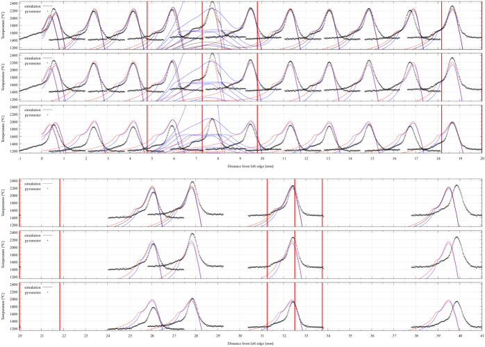
Appendix A Pyrometer maps