Bound states in the continuum accompanied by avoided crossings in leaky-mode photonic lattices
Abstract
When two nonorthogonal resonances are coupled to the same radiation channel, avoided crossing arises and a bound state in the continuum (BIC) appears in parametric space. This paper presents numerical and analytical results on the properties of avoided crossing and BIC due to the coupled guided-mode resonances in one-dimensional leaky-mode photonic lattices with slab geometry. In symmetric photonic lattices with up-down mirror symmetry, Friedrich-Wintgen BICs with infinite lifetime are accompanied by avoided crossings due to the coupling between two guided modes with the same transverse parity. In asymmetric photonic lattices with broken up-down mirror symmetry, quasi-BICs with finite lifetime appear with avoided crossings because radiating waves from different modes cannot be completely eliminated. We also show that unidirectional-BICs are accompanied by avoided crossings due to guided-mode resonances with different transverse parities in asymmetric photonic lattices. The factor of a unidirectional-BIC is finite, but its radiation power in the upward or downward direction is significantly smaller than that in the opposite direction. Our results may be helpful in engineering BICs and avoided crossings in diverse photonic systems that support leaky modes.
I Introduction
The ability to confine light to limited regions is of fundamental importance in both basic science and practical applications. Conventionally, electromagnetic waves can be localized in photonic structures by separating specific eigenmodes away from the continuum of radiating modes. This mode separation can typically be achieved through metallic mirrors, total internal reflections at dielectric interfaces Born2002 , and photonic band gaps in periodic structures Yablonovitch1987 ; Joannopoulos1995 . Optical bound states in the continuum (BICs) are special electromagnetic states that remain well localized in photonic structures even though they coexist with outgoing waves that can carry electromagnetic energy away from the photonic structure Marinica2008 ; Plotnik2011 ; Hsu2016 ; Koshelev2019 ; Koshelev2020 . Diverse types of BICs have been implemented in various photonic systems, including metasurfaces Koshelev2018 ; Kupriianov2019 ; Abujetas2019 , photonic crystals Gansch2016 ; Yang2014 , plasmonic structures Azzam2018 , and fiber Bragg gratings XGao2019 . Recently, robust BICs in subwavelength photonic crystal slab geometry have attracted much attention because they are associated with interesting topological physical phenomena BZhen2014 ; YXGao2017 ; SGLee2019-1 as well as practical applications, such as lasers Kodigala2017 ; STHa2018 , sensors YLiu2017 ; Romano2018 , and filters Foley2014 .
BICs found in slab-type photonic lattices so far can be split into three categories: (i) symmetry-protected BICs, (ii) single-resonance parametric BICs, and (iii) Friedrich-Wintgen BICs. Symmetry-protected BICs appear at the point (the center of the Brillouin zone) due to the symmetry mismatch between their mode profiles and those of external plane waves Kazarinov1985 ; SLi2019 . Single-resonance parametric BICs are found at generic points along dispersion curves when the relevant coupling to the radiation continuum completely vanishs Hsu2013 . Friedrich-Wintgen BICs, which are generally found in the vicinity of the avoided crossing of two dispersion curves, arise because of the destructive interference of two guided-mode resonances coupled to the same radiation channel Bulgakov2018 . Historically, Friedrich and Wintgen presented a general formalism to find BICs in quantum systems in 1985 Friedrich1985 . Recently, it has been shown that the Friedrich-Wintgen formalism is valid to describe optical BICs in photonic structures Mermet-Lyaudoz2019 ; Kikkawa2019 . The aim of the present paper is to address the fundamental properties of avoided crossings and BICs due to coupled guided-mode resonances in one-dimensional (1D) leaky-mode photonic lattices.
When two nonorthogonal resonances generate avoided crossings, BICs with infinite lifetimes appear in parametric space, and the conditions for Friedrich-Wintgen BICs can generally be fulfilled through the fine tuning of structural parameters. In photonic lattice slabs, however, the Friedrich-Wintgen BIC can be found near the avoided crossing in the photonic band structure without the fine tuning of structural parameters. In this study, we investigated BICs and avoided crossing due to two different waveguide modes in photonic lattice slabs with symmetric and asymmetric cladding layers through finite element method (FEM) simulations and temporal coupled-mode formalism. We show that avoided crossings in the photonic lattices with asymmetric cladding layers support only quasi-BICs with a finite value of factor, whereas the avoided crossings with symmetric cladding structures support true-BICs with infinite factor. We also show that unidirectional-BICs are accompanied by avoided crossings due to two guided-mode resonances with different transverse parities in asymmetric photonic lattices. The factor of the unidirectional-BIC is finite but its radiation power in the upward or downward direction is significantly smaller than that in the opposite direction.
II Lattice structure and perspective
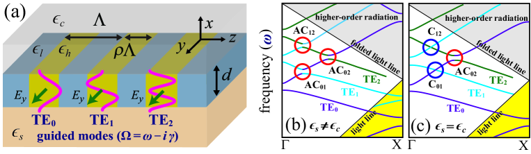
Figure 1 illustrates a 1D photonic lattice and the attendant schematic photonic band structures including avoided crossings. As shown in Fig. 1(a), we model a 1D photonic lattice consisting of high () and low () dielectric constant media. A single periodic layer of thickness is enclosed by a substrate medium (lower cladding) of dielectric constant and cover (upper cladding) of . The period of the lattice is and width of high dielectric constant medium is . This simple lattice supports multiple TE-polarized guided modes, and each mode has its own dispersion curve because the thickness is thick enough and its average dielectric constant is larger than and Magnusson2009 . In dielectric slab waveguides with symmetric (asymmetric) cladding layers (), as schematically illustrated in Fig. 1(a), guided modes are classified into two categories by their transverse mode profiles Agrawal2004 . Even (even-like) modes have even (even-like) transverse electric field profiles, and odd (odd-like) modes have odd (old-like) transverse field profiles with symmetric (asymmetric) cladding layers. In photonic lattices with asymmetric cladding layers, as shown in Fig. 1(b), avoided crossings (in red circles) due to and modes arise when and . In photonic lattices with symmetric cladding layers, as shown in Fig. 1(c), two even modes generate avoided crossing (in red circle), but dispersion curves due to even and odd modes cross each other ( and in blue circles) because even and odd modes are perfectly orthogonal in symmetric waveguide structures. In this study, we limited our attention to the avoided crossings and in asymmetric photonic lattices ( and ) and in symmetric lattices () because these simplest cases clearly demonstrate the key properties of the avoided crossings and BICs in photonic lattice slabs. We consider the avoided crossings only in the white region where quasi-guided modes can couple to external plane waves effectively and generate diverse zero-order spectral responses Niraula2015 ; YHKo2018 ; SGLee2017 . In the yellow region below the light line in the substrate, guided modes are nonleaky and not associated with BICs Johnson1999 . In the gray region above the folded light line, guided modes are less practical because they generate higher-order diffracted waves outside the lattice YDing2007 .
III Results and discussion
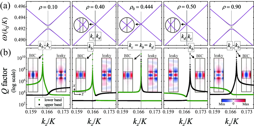
Figure 2(a) shows the evolution of the avoided crossing due to and modes under variation of in the photonic lattice with symmetric cladding layers. As seen in Fig. 2(a), a band gap opens at where two uncoupled dispersion curves cross each other, and its size increases as the value of increases from zero. However, the gap size decreases and becomes zero as is further increased. The bands remain closed for a while in spite of the additional increase in . The band gap reopens and its size grows again, decreases, and approaches zero when is further increased and approaches 1. The Insets of Fig. 2(a) depicting magnified views of the dispersion curves near the crossing point indicate that the degenerate point where the band closes is slightly different from in general. As increases, the relative position of changes from the right to left side of . These band dynamics are associated with the band transition of the Friedrich-Wintgen BIC, as seen by the simulated factors plotted in Fig. 2(b). As increases from zero, the Friedrich-Wintgen BICs with factors larger than appear at near the crossing point . The distance between the location of the BIC and crossing point increases, decreases, and becomes zero when . However, the distance increases again, decreases, and approaches zero as is further increased and approaches 1. The Friedrich-Wintgen BIC across the band gap under the variation of by passing through the degenerate point where two dispersion curves cross as straight lines. The spatial electric field () distributions plotted in the insets of Fig. 2(b) show that the Friedrich-Wintgen BICs, that have -like field distributions, are well localized in the lattice without radiative loss, whereas leaky modes in the opposite band branch with -like field distributions are radiative outside the lattice.
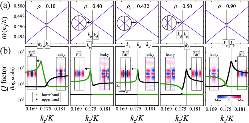
Figure 3(a) illustrates the evolution of the avoided crossing due to and modes of photonic lattices with asymmetric cladding layers. The band dynamics shown in Fig. 3(a) is the same as that in Fig. 2(a). As varies from zero to 1, the band gap opens at , closes at , reopens, and vanishes with . In the evolution process under variation of , there exists a finite range of in which the bands remain closed. The degenerate point becomes the same as when the two dispersion curves cross as straight lines. In the closed band states with , two dispersion curves have low curvatures, as clearly seen in the insets of Figs. 2(a) and 3(a). The most noticeable effect of asymmetric cladding layers on the avoided crossings can be found by comparing the simulated factors illustrated in Fig. 3(b) with those in Fig. 2(b). There exist quasi-BICs with -like spatial electric field distributions around the crossing point in Fig. 3(b). The factors of the quasi-BICs in Fig. 3(b) are saturated to finite values less than at , whereas the values of the Friedrich-Wintgen BICs in Fig. 2(b) seem to diverge to infinity at . The quasi-BICs also pass through the degenerate point and across the band gap under variation of , as do the Friedrich-Wintgen BICs.
The dynamics of avoided crossing and the band transition of the bound states illustrated in Figs. 2 and 3 can be understood from the temporal coupled-mode theory describing the interference of two different resonances in the same resonator WSuh2004 . When two leaky waveguide modes and with complex frequencies and , respectively, are excited in the photonic lattice shown in Fig. 1(a) by the incoming waves , two resonance amplitudes evolve in time as with the Hamiltonian and coupling matrix given by
| (1) |
| (2) |
where denotes the near-field coupling between the guided modes and represents the interference of radiating waves through far-field coupling. Matrix elements and represents the radiative coupling of and modes to the port , respectively. Eigenmodes of the Hamiltonian are a linear combination of and modes, and from the determinant condition , the corresponding eigenvalues are given by
| (3) |
where and . From Eq. (3), we obtain avoided band structures in space. Equation (3) indicates that the real parts of the two eigenvalues are degenerate, and the avoided band closes when the real part in the square root is a negative value and the imaginary part is zero. When with , the band closes at because with and is negative. In Fig. 2(a) with and Fig. 3(a) with , two dispersion curves cross as straight lines at because near-field coupling vanishes with . For a given value of , in the weakly modulated photonic lattice considered herein, the magnitudes of , , and are small and could be approximated as constant values near , but changes from zero to some finite value as a function of . When is slightly deviated from zero with the variation of from , the two conditions and can be fulfilled simultaneously at where , as shown in Figs. 2(a) and 3(a) with . When , on the other hand, bands can be closed at where as shown in Figs. 2(a) and 3(a) with . The avoided band opens when the two conditions cannot be fulfilled simultaneously as is further increased with .
Formation of the Friedrich-Wintgen BICs in Fig. 2(c) and quasi-BICs in Fig. 3(c) can be seen by determining in terms of decay rates. Due to the principle of energy conversation and time-reversal symmetry, the photonic structure shown in Fig. 1(a) supports the relation , and by solving the relation, we have
| (4) |
| (5) |
| (6) |
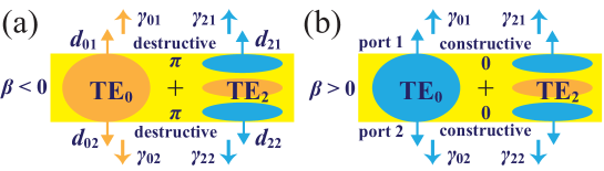
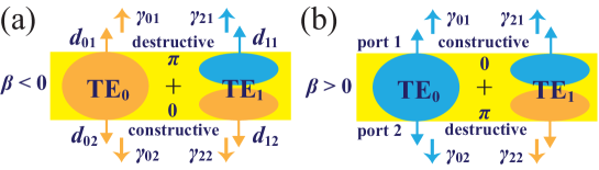
where and represent the phase angles of and , respectively, and and denote the decay rates of and mode to the port , respectively Kikkawa2019 ; WSuh2004 . Considering the avoided crossings between two even (even-like) modes shown in Fig. 2 (Fig. 3), phase angles at port and port satisfy the relation , as conceptually illustrated in Fig. 4. Moreover, it is reasonable to conjecture from Eqs. (4) and (5) that and . Hence, the far-field couplings between two even modes and between two even-like modes can be written as
| (7) |
| (8) |
In Eq. (7), we used and . Coupled guided-mode resonance results in two hybrid eigenmodes. The anti-phase mode with shown in Fig. 4(a) can be a BIC or quasi-BIC because radiating waves from and modes interfere destructively at the two radiation ports simultaneously, and the in-phase mode with in Fig. 4(b) becomes more lossy because radiating waves interact constructively.
Maximal or minimal values of imaginary parts in the eigenvalues of the hybrid eigenmodes can be obtained when the two complex values and in the square root of Eq. (3) are in phase, i.e.,
| (9) |
With Eq. (9), Eq. (3) can be rewritten as
| (10) |
where is a real positive value. In the photonic lattice with symmetric cladding layers, by Eq. (7), is the same as , and the eigenvalue of anti-phase mode with becomes purely real and turns into a BIC at when , as shown in Fig. 2(b) with . When (), the Friedrich-Wintgen BICs with the anti-phase modes appear at () or at the lower (upper) band branch, as shown in Fig. 2(b) with (). In the photonic lattice with asymmetric cladding layers, by Eq. (8), is slightly different from . Therefore , when , a quasi BIC with the nonzero minimal imaginary part in the eigenfrequency appears at , as shown in Fig. 3(b) with . When (), the quasi BICs appear at () or at the lower (upper) band branch, as shown Fig. 3(b) with ().
When two guided modes with different transverse parities ( and ) are coupling, as noted in Fig. 5, radiating waves from different modes interfere constructively at one of the two radiation ports, while they interact destructively at the other port. Because Eqs. (4)–(6) are valid for the coupling between two waveguide modes with different spatial parities, except that , the far-field coupling between an even and an odd mode and between an even-like and odd-like mode can be written as and
| (11) |
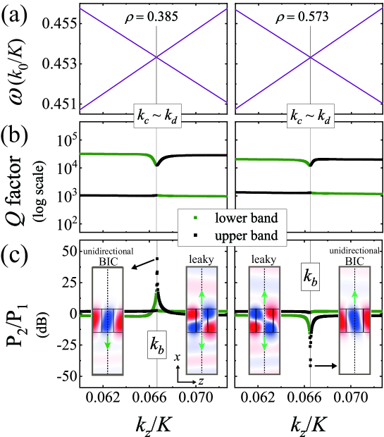
respectively, where we set () when the radiating waves interfere destructively (constructively) at the port 1, for convenience. In the symmetric photonic lattices with , near-field coupling is also zero because the overlap integral of the even and odd modes is zero WSuh2004 . Two dispersion curves for the even and odd modes cross each other, and there is no band gap, as schematically represented in Fig. 1(c). In photonic lattices with asymmetric cladding layers, on the other hand, avoided crossings due to and modes take place because and in general, and their properties can also be described by Eq. (3). Through FEM simulations, we verified that a band gap opens at , closes at , closed band state remains for a while, reopens, and vanishes under variation of from 0 to 1. However, there cannot be a BIC or quasi-BIC due to the phase mismatch of the radiating waves at one of the two radiating ports, as shown in Fig. 5. Instead, we found that there exists a unidirectional-BIC whose decay rate at one port is suppressed by the destructive interference, whereas decay to the opposite port is enhanced by constructive interaction. Figures 6(a), 6(b), and 6(c) show the simulated band structures, factors, and power ratios , where represents the radiation power to port , respectively, when and 0.583. Because the coupling strengths between even-like and odd-like modes are weak, as can be seen in Fig. 6(a), two dispersion curves cross as like straight lines at in the closed band states. Simulated factors in Fig. 6(b) show that there is no BIC or quasi-BIC. However, Fig. 6(c) shows that there exist unidirectional-BICs whose radiation power to the port or port is significantly larger (up to 40 dB) than that to the opposite port. The spatial electric field distributions in the insets of Fig. 6(c) demonstrate that unidirectional-BICs radiate to the only downward (upward) direction when (), but leaky modes on the opposite band branches radiate to the upward and downward directions simultaneously. Here, we showed that unidirectional radiation can be enabled by unidirectional-BICs accompanied by avoided crossings. Very recently, unidirectional radiation has also been realized by utilizing the topological nature of BICs XYin2020 . We believe that the unidirectional radiation associated with BICs in planar photonic lattices is interesting and could be utilized to increase the efficiency of diverse optical devices, such as vertically emitting lasers and grating couplers.
IV Conclusion
In conclusion, we have investigated avoided crossings and BICs in 1D leaky-mode photonic lattices through FEM simulations and temporal coupled-mode theory. When two guided-mode resonances are coupled, photonic band gaps arise by avoided crossings and BICs appearing in photonic band structures without the fine tuning of structural parameters. The widths of avoided band gaps vary by lattice parameters. In particular, there exist closed band states in which avoided bands remain closed under variation of fill factor . In photonic lattice slabs with symmetric cladding layers, true-BICs with, in principle, infinite factor are accompanied by avoided crossings due to two guided modes with the same transverse parity. In the coupling process, two guided modes interact as in-phase or anti-phase. Anti-phase mode becomes a BIC because radiating waves from different modes vanish completely by destructive interference and in-phase mode gets more lossy with constructive interference. In photonic lattices with asymmetric cladding layers, on the other hand, only quasi-BICs with finite factor are accompanied because the radiating waves by different modes cannot be completely eliminated. True- and quasi-BICs appear across the band gap by passing through a degenerate point where two dispersion curves cross as straight lines. We also show that unidirectional-BICs are accompanied by avoided crossings due to two guided modes with different transverse parities in asymmetric photonic lattices. The factor of the unidirectional-BIC is finite but its radiation power in the upward or downward direction is significantly smaller than that in the opposite direction. Our research here is limited to the BICs and avoided crossings associated with the lowest three guided modes , , and in 1D photonic lattices. However, extension of this work to BICs and avoided crossings associated with higher order guided modes and 2D lattices is feasible. This contribution may be helpful in engineering BICs in diverse optical systems supporting leaky-modes.
This research was supported by a grant from the National Research Foundation of Korea funded by the Ministry of Education (No. 2020R1I1A1A01073945) and Ministry of Science and ICT (No. 2020R1F1A1050227), along with the Gwangju Institute of Science and Technology Research Institute in 2020.
References
- (1) M. Born and E. Wolf, Principles of Optics, (Cambridge University Press, Cambridge, 2002).
- (2) E. Yablonovitch, “Inhibited Spontaneous Emission in Solid-State Physics and Electronics,” Phys. Rev. Lett. 58(20), 2059–2062 (1987).
- (3) J. D. Joannopoulos, R. D. Meade, and J. N. Winn, Photonic Crystals: Molding the Flow of Light, (Princeton University, 1995).
- (4) D. C. Marinica, A. G. Borisov, and S. V. Shabanov, “Bound States in the continuum in photonics,” Phys. Rev. Lett. 100, 183902 (2008).
- (5) Y. Plotnik, O. Peleg, F. Dreisow, M. Heinrich, S. Nolte, A. Szameit, and M. Segev,“Experimental observation of optical bound states in the continuum,” Phys. Rev. Lett. 107, 183901 (2011).
- (6) C. W. Hsu, B. Zhen, A. D. Stone, J. D. Joannopoulos, and M. Soljačić, “Bound states in the continuum” Nature Reviews Materials 1, 1–13 (2016).
- (7) K. Koshelev, G. Favraud, A. Bogdanov, Y. Kivshar, and A. Fratalocchi, “Nonradiating photonics with resonant dielectric nanostructures,” Nanophotonics 8, 725–745 (2019).
- (8) K. Koshelev, S. Kruk, E. Melik-Gaykazyan, H.-H. Choi, A. Bogdanov, H.-G. Park, Y. Kivshar, “Subwavelength Dielectric Resonators for Nonlinear Nanophotonics,” Science 367 288–292 (2020).
- (9) K. Koshelev, S. Lepeshov, M. Liu, A. Bogdanov, and Y. Kivshar, “Asymmetric metasurfaces with high-Q resonances governed by bound states in the continuum,” Phys. Rev. Lett. 121(19), 193903 (2018).
- (10) A. S. Kupriianov, Y. Xu, A. Sayanskiy, V. Dmitriev, Y. S. Kivshar, and V. R. Tuz,“Metasurface engineering through bound states in the continuum,” Phys. Rev. Appl. 12(1), 014024 (2019).
- (11) D. R. Abujetas, N. van Hoof, S. ter Huurne, J. G. Rivas, and J. A. Sánchez-Gil, “Spectral and temporal evidence of robust photonic bound states in the continuum on terahertz metasurfaces,” Optica 6(8), 996–1001 (2019).
- (12) R. Gansch, S. Kalchmair, P. Genevet, T. Zederbauer, H. Detz, A. M. Andrews, W. Schrenk, F. Capasso, M. Lončar, and G. Strasser, “Measurement of bound states in the continuum by a detector embedded in a photonic crystal,” Light: Sci. Appl. 5(9), e16147 (2016).
- (13) Y. Yang, C. Peng, Y. Liang, Z. Li, and S. Noda, “Analytical perspective for bound states in the continuum in photonic crystal slabs,” Phys. Rev. Lett. 113(3), 037401 (2014).
- (14) S. I. Azzam, V. M. Shalaev, A. Boltasseva, and A. V. Kildishev, “Formation of bound states in the continuum in hybrid plasmonic-photonic systems,” Phys. Rev. Lett. 121(25), 253901 (2018).
- (15) X. Gao, B. Zhen, M. Soljačić, H. Chen, and C. W. Hsu, “Bound states in the continuum in low-contrast fiber Bragg gratings,” ACS Photonics 6, 2996–3002 (2019).
- (16) B. Zhen, C. W. Hsu, L. Lu, A. D. Stone, and M. Soljačić, “Topological nature of optical bound states in the continuum” Phys. Rev. Lett. 113(25), 257401 (2014).
- (17) Y.-X. Xiao, G. Ma, Z.-Q. Zhang, and C. T. Chan, “Topological subspace-induced bound state in the continuum,” Phys. Rev. Lett. 118(16), 166803 (2017).
- (18) S.-G. Lee and R. Magnusson, “Band flips and bound-state transitions in leaky-mode photonic lattices,” Phys. Rev. B 99(4), 045304 (2019).
- (19) A. Kodigala, T. Lepetit, Q. Gu, B. Bahari, Y. Fainman, and B. Kanté, “Lasing action from photonic bound states in continuum,” Nature 541, 196–199 (2017).
- (20) S. T. Ha, Y. H. Fu, N. K. Emani, Z. Pan, R. M. Bakker, R. Paniagua-Domínguez, and A. I. Kuznetsov, “Directional lasing in resonant semiconductor nanoantenna arrays” Nat. Nanotechnol. 13, 1042–1047 (2018).
- (21) Y. Liu, W. Zhou, and Y. Sun, “Optical refractive index sensing based on high-Q bound states in the continuum in free-space coupled photonic crystal slabs,” Sensors (Basel) 17(8), 1861 (2017).
- (22) S. Romano, A. Lamberti, M. Masullo, E. Penzo, S. Cabrini, I. Rendina, and V. Mocella, “Optical biosensors based on photonic crystals supporting bound states in the continuum,” Materials (Basel) 11(4), 526 (2018).
- (23) J. M. Foley, S. M. Young, and J. D. Phillips, “Symmetry-protected mode coupling near normal incidence for narrow-band transmission filtering in a dielectric grating,” Phys. Rev. B 89(16), 165111 (2014).
- (24) R. F. Kazarinov and C. H. Henry, “Second-order distributed feedback lasers with mode selection provided by first-order radiation loss,” IEEE J. Quantum Electron. 21(2), 144–150 (1985).
- (25) S. Li, C. Zhou, T. Liu, and S. Xiao, “Symmetry-protected bound states in the continuum supported by all-dielectric metasurfaces,” Phys. Rev. A 100(6), 063803 (2019).
- (26) C. W. Hsu, B. Zhen, J. Lee, S.-L. Chua, S. G. Johnson, J. D. Joannopoulos, and M. Soljačić, “Observation of trapped light within the radiation continuum,” Nature 449, 188–191 (2013).
- (27) E. N. Bulgakov and D. N. Maksimov, “Avoided crossings and bound states in the continuum in low-contrast dielectric gratings,” Phys. Rev. A 98,(5), 053840 (2018).
- (28) H. Friedrich and D. Wintgen, “Interfering resonances and bound states in the continuum” Phys. Rev. A 32, 3231 (1985).
- (29) R. Mermet-Lyaudoz, F. Dubois, N. Hoang, E. Drouard, L. Berguiga, C. Seassal, X. Letartre, P. Viktorovitch, and H. S. Nguyen, “Realization of bound state in the continuum induced by vertical symmetry breaking in photonic lattice,” arXiv:1905.03868 (2019).
- (30) R. Kikkawa, M. Nishida, and Y. Kadoya Y, “Polarization-based branch selection of bound states in the continuum in dielectric waveguide modes anti-crossed by a metal grating,” New J. Phys. 21, 113020 (2019).
- (31) R. Magnusson and M. Shokooh-Saremi, “Physical basis for wideband resonant reflectors” Opt. Express 16(5), 3456–3462 (2008).
- (32) G. P. Agrawal, Lightwave Technology: Components and Devices, (Wiley Sons, 2004).
- (33) M. Niraula, J. W. Yoon, and R. Magnusson, “Single-layer optical bandpass filter technology,” Opt. Lett. 40(21), 5062–5065 (2015).
- (34) Y. H. Ko and R. Magnusson, “Wideband dielectric metamaterial reflectors: Mie scattering or leaky bloch mode resonance?” Optica 5(3), 289–294 (2018).
- (35) S.-G. Lee, S. H. Kim, K. J. Kim, and C. S. Kee, “Polarization-independent electromagnetically induced transparency-like transmission in coupled guided-mode resonance structures,” Appl. Phys. Lett. 110(11), 111106 (2017).
- (36) G. Johnson, S. Fan, P. Villeneuve, J. D. Joannopoulos, and L. Kolodziejski, “Guided modes in photonic crystal slabs,” Phys. Rev. B 60, 5751–5758 (1999).
- (37) Y. Ding and R. Magnusson, “Band gaps and leaky-wave effects in resonant photonic-crystal waveguides,” Opt. Express 15(2), 680–694 (2007).
- (38) W. Suh, Z. Wang, and S. Fan,“Temporal coupled-mode theory and the presence of non-orthogonal modes in lossless multimode cavities,” IEEE J. Quantum Electron. 40(10), 1511–1518 (2004).
- (39) X. Yin, J. Jin, M. Soljačić, C. Peng, and B. Zhen, “Observation of topologically enabled unidirectional guided resonances,” Nature 580, 467–471(2020).