Enhanced space charge limited current for curved electron emitters
Abstract
The maximum current that can be transported across a vacuum diode is limited by forces arising due to space charge. In a planar diode, the space charge limited (SCL) current density from an emitting patch is given by the Child-Langmuir (CL) law where is the potential difference across the diode and is the separation between the anode and cathode. We show here analytically using the nonlinear line charge model that for a curved emitter in a planar diode configuration, the limiting current obeys the scaling relationship where is the apex field enhancement factor of the curved emitter. For an emitter with large height () to apex radius of curvature () ratio, the limiting current far exceeds the planar value. The result is verified using the particle-in-cell code PASUPAT for two curved emitters shapes.
I Introduction
The maximum current that can be transported across a vacuum diode is a quantity of immense interest in vacuum micro-electronics, space navigation and especially in high-power vacuum electronic devices such as magnetron, gyrotron, vircator or relativistic backward wave oscillators benford . The limit on the current arises due to space charge which give rise to an electric field that opposes the macroscopic applied field in the diode. The current that enables an exact cancellation of these forces is referred to as the space charge limited (SCL) current. It is a quantity that can be reliably used to design systems and is used to model explosive emission benford in particle-in-cell (PIC) codes.
In a planar diode configuration, the SCL current density is given by the Child-Langmuir (CL) law child ; langmuir
| (1) |
where and are the electronic charge and mass respectively, is the potential difference across anode-cathode gap and refers to the distance between them. Eq. (1) strictly holds for a diode where the parallel plates are infinite in extent and the entire cathode participates in emission. Such a situation may approximate the case when the plate separation is very small compared to the size of the emitting region. When they are comparable, a correction factor needs to be incorporated luginsland96 ; lau ; luginsland2002 ; zhang2017
In recent decades, emission from curved surfaces under the application of an electric field has been extensively researched. A curved emitter placed perpendicular to the cathode plate in a planar diode configuration, has a local electric field at the apex which can be expressed as where is the macroscopic field and . This leads to larger field emission (FE) currents at moderate fields and can hasten the transition from cold-FEforbes2007 to thermal-FEjensen2006 and finally to explosive emission in high power systemsbenford ; FE_relevance ; forbes2008 ; jensen2015 . In such situations of emission from a curved surface, the space charge limited current is expected to increase and its exact nature is a matter of considerable interest. A clue that the scaling relationship should continue to hold for curved emitters, follows from the general scaling law for Schrödinger-Poisson system arrived at using dimensional analysis biswas_epl wherein where , being the Plank constant. For a purely classical system so that irrespective of the emitter shapeother_combinations .
The limiting current is known analytically for co-axial cylindrical diodes and concentric spherical diode systems apart from the planar (Cartesian) system zhang2017 ; LB23 ; LB24 ; zhu2013 ; darr2019 . A similar treatment for a curved emitter in a planar diode configuration seems beyond the scope of standard techniques and it is therefore necessary to take recourse to approximate analytical methods and PIC codes where space-charge limited emission from curved surfaces is modeled adequately. The aim of this work is to establish an extension of the Child-Langmuir law for curved emitters. This is especially important keeping in mind the fact that cathode designs are often made using the vacuum electric field (in the absence of charges) at the cathode, . Thus the planar Child-Langmuir current density may be expressed aszhang2017 and its collisional counterpart, the Mott-Gurney law as . Since the cathode field at the apex of a curved emitter gets enhanced by a factor , this would imply a scaling . It is thus important to investigate whether such a scaling in fact holds.
II Approximate derivation of SCL current
The space charge limited current zhang2017 ; puri for zero injection velocity corresponds to the condition that the net electric field at the cathode is zero. We shall use approximate methods which incorporates this basic requirement and highlights the physical aspects. A simple derivation of the Child-Langmuir law based on vacuum capacitance and transit time rose55 ; umstattd ; zhang2017 provides much physical insight.
II.1 The Planar Case
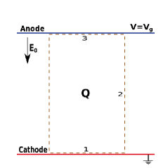
Consider a planar diode with the anode and cathode separated by a distance and having a potential difference . The electric field between the plates is and the induced surface charge density on the cathode plate is . The total charge induced on an area is thus . This is also the magnitude of the charge induced on the anode on an identical area since the field lines remain straight and perpendicular to the plates.
In order to address the question of space charge limited current, consider a charge filled flux tube having a cross-sectional area and extending from the cathode () to the anode (). Let the total charge contained be such that the net field (the macroscopic field and the space charge field) at the cathode is zero. It is assumed here that the field lines remain straight and perpendicular to the plates in the presence of the free charge (see Fig. 1). Consider, a Gaussian surface covering this tubular volume (dashed lines), with the faces parallel to the plates (marked 1 and 3) infinitesimally away from them. Since the net field at the cathode is zero, for the face (1) near the cathode. The flux through the transverse surface (labeled 2) is also zero while the flux though the surface near the anode is assuming that the field at the anode remains in the presence of the charge . In reality the field at the anode with . Thus, the approximate total flux through the Gaussian surface is so that the free charge needs to reside in the diode in order that the field at the cathode is zero.
Assuming now that the average transit time between the plates is where is the average speed and is the maximum speed, the space charge limited current through the diode is . Note that in the actual planar 1-D situationSCLpot ; chauvin , the average speed is where while . Thus as in the Child-Langmuir law of Eq. (1) instead of . The approximate result is however close to the exact result and the derivation is considerably simpler.
II.2 SCL current for a curved emitter
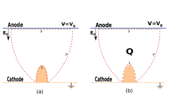
We shall follow a similar procedure to determine the approximate SCL current for a curved emitter. In order to keep the derivation simple, we shall consider a hemi-ellipsoidal emitter of height and apex radius of curvature mounted on the cathode plane. As before, consider the diode without any free charge. Let the charge induced on the hemi-ellipsoidal emitter be . Consider a flux tube as a Gaussian surface as shown in Fig. 2a consisting of surfaces 1,2 and 3. Since surface 1 is inside the hemi-ellipsoid, the flux through this is zero. Further, surface 2 is aligned along the field lines and hence the flux is again zero. The flux through surface 3 is where is the cross-sectional area of the flux tube at the anode which is so far unknown. It follows from Gauss’s law that . Thus, can be determined if can be calculated.
For a hemi-ellipsoid with the anode far away, the induced charge can be determined since the exact solution is known. It has also been established biswas_nonlinear that the surface charge density can be projected on the axis as a line charge having linear density where biswas_nonlinear ; pogorelov for sufficiently large. The total bound charge therefore is Combining the expressions for and , we have where kosmahl ; pogorelov ; biswas_universal is the field enhancement factor at the apex of the hemi-ellipsoidal emitter (the local field at the apex is thus ). Thus where we have used where is the radius of the hemiellipsoid base.
We are now in a position to deal with the space charge limited current. Consider the Gaussian surface shown in Fig. 2b containing free charge . In the SCL limit, the field on surface 1 is zero. We shall assume surfaces 2 and 3 to be identical to Fig. 2a. Thus, the flux through surface 2 is approximately zero while the flux through surface 3 is . Using Gauss’s law, the free charge . Assuming as in the planar case that the average velocity , the SCL current for a curved emitter is
| (2) |
Compared to a planar emitter of area , the SCL current for a curved emitter is greater by a factor .
As in the planar case, there are a number of approximations that may alter the factor . These include the field at the anode, the average transit time and finally the assumption that the does not change in the presence of charges. The scaling should however be preserved despite these approximations.
An extension to a general axially symmetric curved emitter is somewhat non-trivial but can be similarly carried out by noting that the projected line charge density is in general nonlinear and has the form biswas_universal . Thus,
| (3) |
where biswas_universal . Thus, the total charge contained in the diode such that the field on cathode vanishes is where is a nonlinear correction factor that is a-priori unknown. Note that for a hemi-ellipsoid, so that .
Using the expression for average velocity as before, it follows that Thus, the linear dependence on the apex field enhancement factor is expected for other emitter shapes as well.
II.3 Incorporating Anode-Proximity and Shielding
The analysis so far has been for an isolated curved emitter. We shall now consider two competing effects that have been ignored so far, each of which affects the apex field enhancement factor. The presence of the anode in close proximity to the emitter-apex alters the line charge density. Thus the expression for no longer holds and it is necessary to include the effect of charges induced on the anode anodeprox . The net effect is an increase in local field at the emitter apex.
The presence of other emitters in close proximity also alters the local field at the apex due to electrostatic shielding db_rudra1 ; rudra_db . In such a situation, the local field decreases compared to its isolated value. Finally, the presence of other emitters coupled with the anode also contributes enormouslydb_rudra2 ; db_hybrid . Fortunately, all of these effects can be incorporated approximately to express asdb_rudra2 where accounts for anode-proximity of an isolated emitter, accounts for shielding due to all other emitters and is the indirect effect of other emitters mediated through the anode. The apex field enhancement factor thus takes the form so that the relation continues to hold. Similarly the expression for applies for a nonlinear line-charge in the presence of other emitters and the anode. Thus, the central results for SCL current arrived at earlier in this section, continue to hold.
III Results for curved emitters using PIC
III.1 Comparison with an existing result
In [zhu2015, ], the localized current density at the apex of a hyperboloid was reported to scale as with . This appears to be at variance with the results derived here and therefore needs scrutiny.
A diode in [zhu2015, ] consists of two hyperboloids, one of which is a plane at acting as an anode and the other (cathode) with its apex located at having an apex radius of curvature . The local field at the apex is for so that the enhancement factor can be expressed as .
III.2 Comparison using the PIC code PASUPAT
In order to further validate the analytical findings reported here, we shall use a three dimensional fully electromagnetic relativistic PIC codeBirdsall named PASUPAT developed by the authors. It uses the Yee grid based Finite Difference Time Domain Method to solve Maxwell’s equations in electromagnetic solver module yee ; Taflove ; Inan_Marshal . The code also has an electrostatic solver, which currently uses the multigrid methodmultigrid to solve Poisson equation. The charge-conserving current weighting scheme of Esirkepovesirkepov is used to assign current densities to the grid points and the standard Boris methodBirdsall is employed to move the charged particles. Apart from the Dirichlet and Neumann boundary conditions, a variety of open boundary conditions have been incorporated both in the electromagnetic and electrostatic POP_es_abc modules. For handling curved surfaces, the electromagnetic solver uses the the Dey-Mitra algorithmDM ; Benkler while for the electrostatic solver, the discretization scheme in the cut-cell (computational cell lying partially inside two medium) has been modified to account for the reduced spacing between mesh pointscut-cell-ES . For space-charge limited emission from curved surfaces, we have adapted the algorithms presented in [SCL_LL, ] and [loverich, ]. The code uses VTK vtk library for writing files for visualization of simulation data. PASUPAT has been tested on standard benchmark problems. In the present context, it reproduces the Child-Langmuir law for planar diode, both for the finite and infinite emission area. We shall use it here to study the space charge limited current for curved emitters in a planar diode configuration.
We consider space charge limited emission from (a) a hemi-ellipsoid emitter and (b) a hemi-ellipsoid on a cylindrical post (HECP). The anode, cathode and emitter are assumed to be perfect electric conductors. Periodic boundary condition imposed on the side walls of the simulation domain. Typical anode-cathode gap was taken to be m while the number of computational cells along direction of propagation of beam, , was typically 256 or 512, while in the transverse direction and were taken to be 128. We have checked for convergence against , , and time step . The total number of macro-particles is typically .
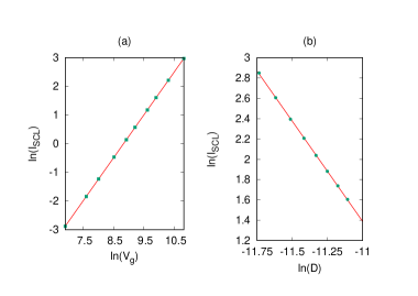
Fig. 3 shows the voltage scaling for an HECP emitter in a parallel plate diode configuration. The base radius m, the height of the post is m while the height of the hemiellipsoid-cap is m. We plot in Fig. 3a, against . Fitting a straight line yields a slope of 1.49 which is close to analytical prediction . The scaling with anode-cathode plate gap is shown in Fig. 3b (right panel) with kV. Fitting a straight line to the against yields a slope of -1.98. These results further validate the voltage () and anode-cathode gap () scaling for curved emitters arrived at analytically. A similar scaling has been found to hold for the hemi-ellipsoid emitter.
Finally, we present our study of variation of anode current with the apex field enhancement factor in Fig. 4. The left panel (Fig. 4a) shows the result for a hemiellipsoid. The enhancement factor is changed by varying the height of the hemiellipsoid while keeping the base radius fixed. The solid points are results obtained from PIC simulation while the straight line is best fit. It is clear that as predicted by our theory, anode current scales linearly with .
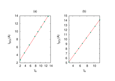
We next consider an emitter having a hemi-ellipsoid end-cap mounted on top of a cylindrical post, a clear case of a nonlinear line charge density. As in the simulation study presented above, we change the height of emitter to change the apex field enhancement factor. The space charge limited current for different is plotted in the right panel (Fig. 4b). As before, solid points represent PASUPAT simulation data and line is best fit. It is evident again that the SCL current scales linearly with . We have tested these results for other geometries as well.
In conclusion, we have established that the space charge limited current for curved emitters obeys
the scaling relationship which reduces to the Child-Langmuir law for .
Importantly, the scaling with is linear and not or that
a straightforward extension of the planar law would imply.
Data Availability: The data that supports the findings of this study are available within the article.
Acknowledgements — The authors acknowledge the contributions of Vibhuti Duggal and Kislay Bhatt in the parallelization of PASUPAT and thank Computer Division, BARC for discussions and valuable support.
IV References
References
- (1) J. Benford, J. A. Swegle, and E. Schamiloglu, High Power Microwaves, Taylor & Francis Group, New York (2007).
- (2) C. D. Child, Phys. Rev. 32, 492 (1911).
- (3) I. Langmuir, Phys. Rev. 2, 450 (1913).
- (4) J. W. Luginsland, Y. Y. Lau, and R. M. Gilgenbach, Phys. Rev. Lett. 77, 4668 (1996).
- (5) Y. Y. Lau, Phys. Rev. Lett. 87, 278301 (2001).
- (6) J. W. Luginsland, Y. Y. Lau, R. J. Umstattd, and J. J. Watrous, Phys. Plasmas 9, 2371 (2002).
- (7) P. Zhang, A. Valfells, L. K. Ang, J. W. Luginsland, and Y. Y. Lau, Appl. Phys. Rev. 4, 011304 (2017).
- (8) R. G. Forbes and J. H. B. Deane, Proc. R. Soc. A.463, 2907 (2007).
- (9) K.L.Jensen, Appl. Phys. Lett. 88, 154105 (2006).
- (10) The CL current density is not directly relevant for pure field emission since the electrostatic field at the cathode is not driven to zero by the space charge, at least in planar casesforbes2008 ; jensen2015 . The SCL analysis, originally made for thermionic emission, is relevant in situations where an ‘infinite’ source of electrons is present, such as due to the formation of a cathode plasma in explosive emissionbenford .
- (11) R. Forbes, J. Appl. Phys., 104, 084303 (2008).
- (12) K. L. Jensen, D. A. Shiffler, I. M. Rittersdorf, J. L. Lebowitz, J. R. Harris, Y. Y. Lau, J. J. Petillo, W. Tang, and J. W. Luginsland, J. Appl. Phys. 117, 194902 (2015).
- (13) D. Biswas and R. Kumar, EPL 102, 58002 (2013).
- (14) For a diode with other length scales apart from , the denominator can have quadratic combinations other than .
- (15) I. Langmuir and K. B. Blodgett, Phys. Rev. 22, 347 (1923).
- (16) I. Langmuir and K. B. Blodgett, Phys. Rev. 24, 49 (1924).
- (17) Y. B. Zhu, P. Zhang, A. Valfells, L. K. Ang, and Y. Y. Lau, Phys. Rev. Lett. 110, 265007 (2013).
- (18) A. M. Darr and A. L. Garner, Appl. Phys. Lett. 115, 054101 (2019).
- (19) R. R. Puri, D. Biswas, and R. Kumar, Phys. Plasmas 11, 1178 (2004).
- (20) A. Rose, Phys. Rev. 97, 1538 (1955).
- (21) R. J. Umstattd, C. G. Carr, C. L. Frenzen, J. W. Luginsland and Y. Y. Lau, American Journal of Physics 73, 160 (2005).
- (22) The space-charge limited electrostatic potential for a parallel plate diode is . It satisfies the Poisson equation where . See for instance Eq. (55) of [chauvin, ]. It follows that and .
- (23) N. Chauvin, ‘Space-charge effect’, DOI: 10.5170/CERN-2013-007.63, https://arxiv.org/abs/1410.7991
- (24) D. Biswas, G. Singh, and R. Kumar, J. Appl. Phys. 120, 124307 (2016).
- (25) E. G. Pogorelov, A. I. Zhbanov, and Y. C. Chang, Ultramicroscopy 109, 373 (2009).
- (26) H. G. Kosmahl, IEEE Trans. Electron Devices 38, 1534 (1991).
- (27) D Biswas, Phys. Plasmas 25, 043113 (2018).
- (28) D. Biswas, Physics of Plasmas, 26, 073106 (2019).
- (29) D. Biswas and R. Rudra, Physics of Plasmas 25, 083105 (2018).
- (30) R. Rudra and D. Biswas, AIP Advances, 9, 125207 (2019).
- (31) D. Biswas and R. Rudra, J. Vac. Sci. Technol. B, J. Vac. Sci. Technol. B, 38, 023207 (2020).
- (32) D. Biswas, preprint, https://arxiv.org/abs/2005.05700
- (33) Y. B. Zhu and L. K. Ang, Physics of Plasmas, 22, 052106 (2015).
- (34) C K Birdsall and A. B. Langdon, “Plasma Physics via Computer Simulation”, New York: McGraw-Hill, 1985.
- (35) K.S. Yee, IEEE Trans. Antennas Propagat., vol. AP-14, No. 3, pp. 302- 307, 1966.
- (36) A. Taflove and S. C. Hagness, “Computational Electrodynamics”, second Edition, Artech House, Boston, 2000.
- (37) U. S. Innan and R. A. Marshal, “Numerical Electromagnetics: The FDTD Method”, Cambridge University Press, Cambridge UK, 2011.
- (38) W. L. Briggs, V. E. Henson, and S. F. McCormick, “A Multigrid Tutorial, 2nd Edition”, SIAM, ISBN: 978-0-89871-462-3, (2000).
- (39) T. Zh. Esirkepov, Comput. Phys. Comm. 135, 144-153 (2001).
- (40) D. Biswas, G. Singh, and R. Kumar Physics of Plasmas 22, 093119 (2015).
- (41) S. Dey and R. Mittra, IEEE Microwave and Guided Wave Letters, VOL. 7, NO. 9, 1997.
- (42) S. Benkler, N. Chavannes and N. Kuster, IEEE Transactions on Antennas and Propagation, 54, 1843 (2006).
- (43) L. N. Dworsky, “Introduction to Numerical Electrostatics Using MATLAB” John Wiley & Sons, Inc. (2014)
- (44) J. J. Watrous, J. W. Luginsland, and G. E. Sasser, Physics of Plasmas 8, 289 (2001).
- (45) J. Loverich, C. Nieter, D. Smithe, S. Mahalingam, and P. Stoltz, “Charge conserving emission from conformal boundaries in electromagnetic PIC simulations”, (2009) Available at https://www.researchgate.net/profile/John_Loverich/publication/
- (46) W. Schroeder, K. Martin and B. Lorensen, “The Visualization Toolkit”, 4rd Edition. Kitware, (2006), ISBN 978-1-930934-19-1. Available at url: http://www.vtk.org