Capillary rise in vuggy media
Abstract
Carbonates are highly heterogeneous formations with large variations in pore size distribution and pore space topology, which results in complex multiphase flow behavior. Here we investigate the spontaneous imbibition behavior of fluids in vuggy carbonates. Glass beads of 1.0 mm diameter, with dissolvable inclusions, are sintered to form multiple configurations of heterogeneous vuggy core with variations in matrix porosity, vug size, vug spatial location, and number of vugs. The core fabrication process is repeatable and allows the impact of vug textural properties to be investigated in a controlled manner.
Capillary rise experiments are conducted in these proxy vuggy carbonate core and compared with the homogeneous non-vuggy core as reference. Continuous optical imaging is performed to track the position of the air-water interface in the cores. To understand the change in capillary height in the presence of a vug, a volume-of-fluid two-phase numerical simulation is performed in a parallel set of connected and disconnected tubes. Finally x-ray tomography scans are performed to identify the shape of the air-water interface in a select few cores.
The results can be summarized as follows: disconnected vugs result in higher capillary rise compared to non-vuggy porous media. The vugs act as capillary barriers, diverting fluid flow to the adjacent connected channels, which ultimately results in a higher overall capillary rise. The results of this work highlight that radius of spontaneous invasion of aqueous phases, such as fracture fluid and hazardous wastes, are affected by vug porosity but not their distribution.
1 Introduction
Carbonate rocks are highly heterogeneous, complex rocks with a variety of pore types, pore shapes, and a wide pore size distribution [1, 2, 3, 4, 5, 6, 7]. The pore size can vary over multiple length scales [8]: the intergranular pores comprise the primary porosity in carbonate rock while dissolution, mineral replacement, and recrystallization [9, 10, 11] can lead to secondary porosity on a localized level [12].
Large disconnected pore spaces, such as vugs, are formed by dissolution and recrystallization of the carbonate rock fabric. Lucia [13] showed that though isolated vugs significantly increase the porosity, they have negligible effect on the overall rock permeability. Fluid flow is controlled by the matrix pore size, and the presence of disconnected vugs fails to improve the capillary entry pressures [14]. Furthermore, these display a higher Archie cementation exponent, and can act as capillary barriers to flow. Mehmani et al. [15] saw a similar behavior in fractures, where the fluid by-passes the fractures and preferentially flows through the matrix. Spontaneous imbibition study for these can improve the understanding of how far the fracturing fluid permeates during the soaking time, and can give an indication about the spatial location of the non-recovered frac fluid [16].
The handling of radioactive elements has been increasing with the global increase in nuclear power generation [17], increasing the probability of a spillage incident occurring. Furthermore, radioactive elements are found in many commercial products that end up in the junkyard at the end of their life cycle, and can potentially leach into the soil. In either case radionuclides can enter the plants through the soil, and spread further within the food chain [18]. From a containment perspective it is pivotal to know the radius of contamination. For a carbonate rock in the presence of a vug, would the vug be filled and limit the radius of damage? Or would the fluid by-pass the vug and penetrate deeper inside the formation?
Micromodels, which are quasi-2D physical models with the pore structure etched on silicon wafers [19], have been extensively used to study 2-phase pore-scale flow mechanisms in porous media [20, 21, 22, 23]. We believe that the quasi-2D micromodels will not be able to capture the capillary flow in presence of a vug, and therefore we have fabricated synthetic glass bead cores with dissolvable inclusions [24] for these experiments.
In this paper we investigate the effect of vug(s) on core rock physics: we generate a set of synthetic glass bead cores with vug(s), experimentally determine petrophysical parameters for these core, observe the behavior of vug(s) on spontaneous imbibition, and contrast with the Washburn [25] solution. Furthermore, we do a computational fluid dynamics (CFD) simulation of spontaneous imbibition in vug-pore models and compare with the experimental results. Finally we perform micro-CT scans on a select few cores and come up with our conclusions.
2 Core preparation
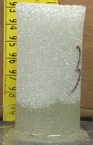
Proxy carbonate cores are fabricated by sintering 1.0 mm diameter glass beads with dissolvable inclusions [24], salt wrapped in cheesecloth, placed in a graphite mold in a muffle furnace in the presence of air.The elevated temperatures soften the glass (Figure 1a) resulting in increased granular surface contact and ultimately a consolidated core. The cheesecloth is burned during the sintering process and the salt is dissolved by flushing the core with de-ionized (DI) water after it cools down. Alternatively, gypsum cement can be used as the dissolvable inclusion [26], which is cleared by flushing with HCl acid.
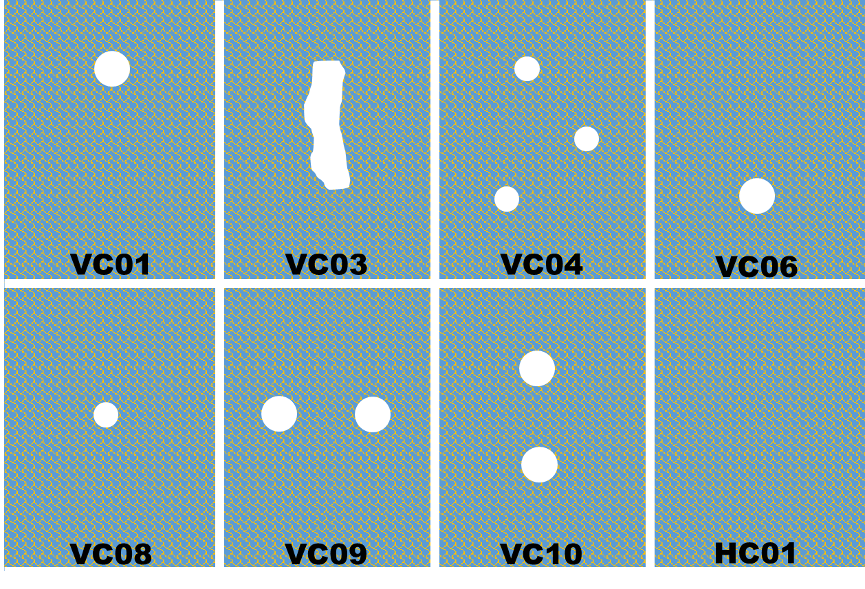
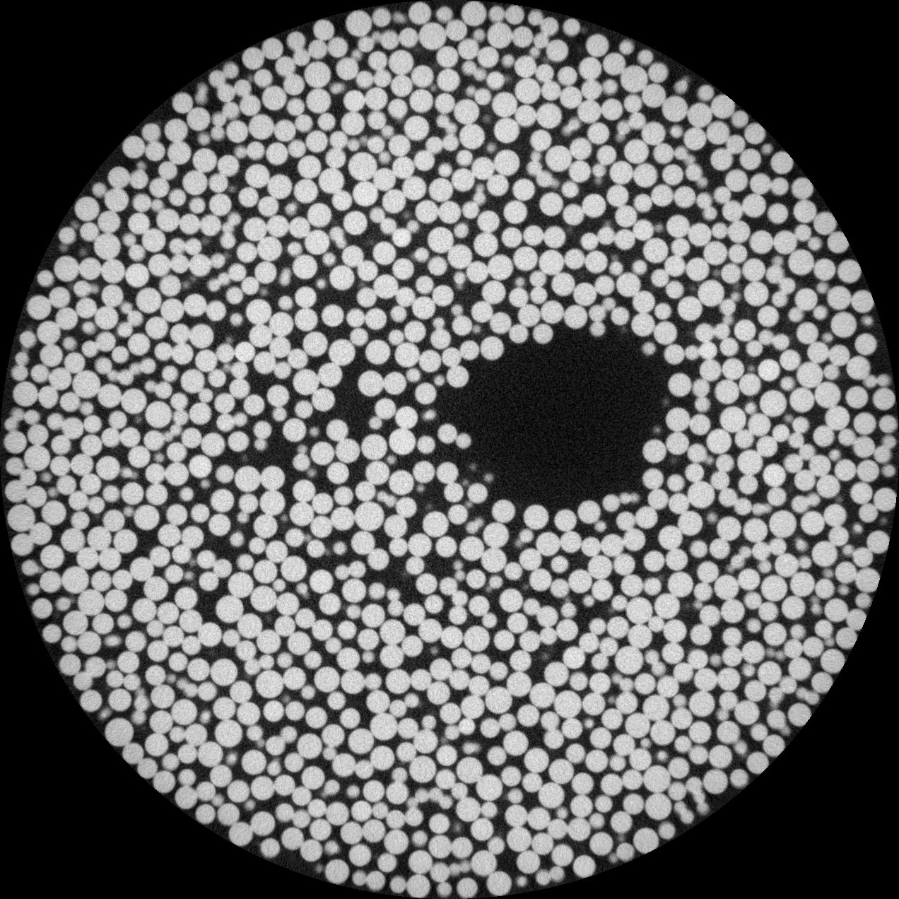
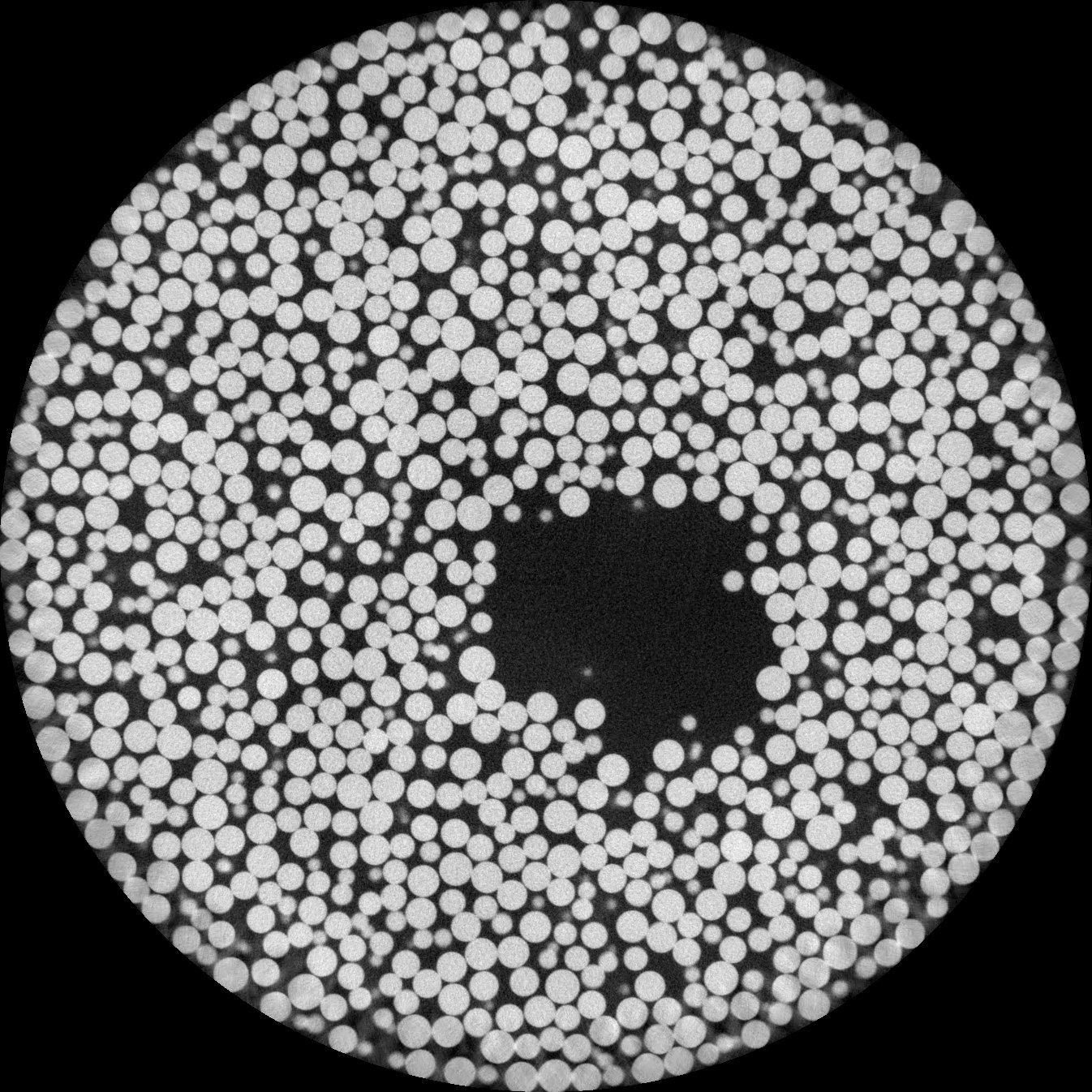
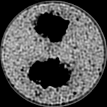
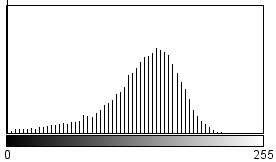
Here we fabricate multiple glass bead cores with different vug heterogeneities (Figure 2) using the temperature profile with a peak temperature of 725 C and exposure time of 15 minutes (Figure 1a). The matrix porosity values is measured as 41% (Figure 1b) and can be altered by varying the peak temperature and exposure time. Micro-CT scan across the middle of the vug for two different cores (Figure 3) show well-defined vug boundaries and no salt/cheesecloth residue.
2.1 Core-fluid petrophysical properties
The petrophysical properties for all the fabricated cores are determined experimentally. The methods are outlined below and the petrophysical values for all the cores are presented in Table 1.
| Core No | (%) | (Darcy) | Vug vol. (frac.) | () |
| VC01 | 41.0 | 978 | 0.024 | 384 |
| VC03 | 50.2 | 12417 | 0.109 | 1477 |
| VC04 | 44.9 | 420 | 0.039 | 203 |
| VC06 | 43.2 | 692 | 0.021 | 291 |
| VC08 | 43.9 | 404 | 0.014 | 203 |
| VC09 | 52.9 | 430 | 0.049 | 169 |
| VC10 | 53.8 | 456 | 0.032 | 171 |
| HC01 | 41.6 | 100 | NO VUG | 97.8 ‡ |
‡ Figure 1b
Porosity using computerized tomography (CT) imaging
Core porosity is determined using an in-house modified medical computed tomography scanner from Universal Systems (HD-350E). The core is 100% saturated with DI water, placed in the CT scanner, and scanned at a resolution of 250 m. The scan parameters used are: 3 seconds scan time, 3 mm scan thickness, 3 mm scan point distance, 100 keV voltage, and 100 mA current. Since the core volume consists of only glass beads and DI water, the porosity can be determined by taking a weighted average (Eq. 1) of the individual CT values for these two substances. The CT number for DI water and glass beads for this machine have been measured to be 25 HU and 2500 HU respectively.
| (1) |
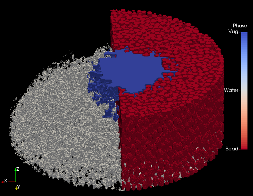
The CT output is segmented (Figure 4a) using the Otsu method [27] and the vug is isolated by using a connected region algorithm in ImageJ-Fiji [28, 29].The two parallel vug surface are visualized in Figure 4b.


Single phase permeability using constant flow injection
Single-phase liquid permeability of the cores is determined by pumping DI water through the core at variable flow rate (40, 50, and 60 ml/min) and measuring the pressure drop along the core. The pressure drop is used to calculate the liquid permeability using single-phase Darcy's law.
Average pore throat radius
The pore distribution in the homogeneous core (Figure 1b) is determined by using an in-house Oxford Instruments GeoSpec2 NMR scanner with the average pore size calculated as 97.8 m.
This scanner can measure a maximum pore size of 350 m before which the bulk relaxivity of the water dominates. The vugs introduced in the core are generally larger than this, therefore we use a theoretical Pittman R50 equation [30] (Eq. 2) to determine the average pore radius for the vuggy cores.
| (2) |
Contact angle
Contact angle measurements are made using a static sessile drop contact angle using a goniometer. The air/water contact angle on a sintered glass bead sheet, fabricated in presence of cheese cloth, was found to vary between 48°– 50°.
Surface tension
The surface tension of the air/water system is experimentally determined by conducting capillary rise in fixed diameter tubing. Two plastic tubes, with inner diameters 2.367 mm and 1.605 mm, are placed vertically in DI water and the elevation of air/water interface from the top of the fluid level is measured via a 2D tomogram. The contact angle of the setup is determined from the tomogram and the surface tension (Eq. 3) for the air-water system is calculated as 51.2 mN/m.
| (3) |
Porosity-permeability crossplot
Porosity-permeability crossplot for the vuggy and homogeneous cores is plotted in Figure 5, along with the k/ ratio contours. The contours trace points with similar flow quality [31] and show three distinct flow units (FU) for the samples. FU-1 (colored blue in Figure 5) has the lowest flow quality with a k/ value of , FU-2 (red) has a k/ value of , and FU-3 (green) has the best flow quality with a k/ value of .
The presence of vug affects the flow unit classification of the core as observed via the departure of the points from the homogeneous core. The impact is more pronounced at the higher vug volume ratio: VC03 with a vug volume ratio 0.1 occupies FU-3 with a k/ of 2.47105. Overall, we find that the spatial distribution and location of the vug does not have any impact on the flow unit classification.
3 Capillary rise
3.1 Experiment methodology
Capillary rise over time is measured for all the carbonate proxy cores (Figure 2): the core is placed in a Petri dish filled with DI water to a height of 10 mm and the water front movement is recorded by continuous optical imaging (Huawei Nexus 6P camera – 12.3 MP Sony Exmor IMX377 with 4K video capture) at a frequency of 120 frames/second. The output video is converted to an image stack and binarized to determine the position of the air-water interface with time.
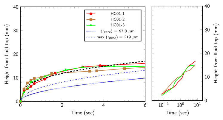
Three iterations of HC01 are produced and the capillary rise experiment is performed in each of them. A similar capillary rise profile is observed in all of them (Figure 6): a sharp initial increase which lasts for the first 0.15 seconds followed by a logarithmic decline. The capillary rise is plotted along with the analytical solution for the Washburn equation in a grain pack [32] for the experimentally determined maximum and average pore radii (Figure 1b). The solution, which assumes a continuous and uniform porous medium bounded on the sides and is not true in this case, and is not able to capture the initial sharp fluid rise and ultimately under-predicts the total capillary rise.
Compensating for the initial sharp fluid rise by transposing the solution to the end of that segment (black dashed line in Figure 6 left) captures the curve nicely and results in a better match with the experimental observations. The capillary rise follows the Lucas–Washburn law [25] (Figure 6 right), which is consistent with previous studies in spontaneous imbibition in homogeneous porous media [33, 34].
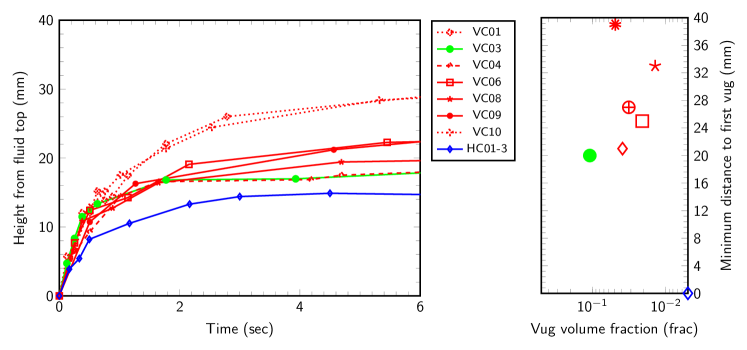
Capillary rise in all the vuggy cores is plotted in Figure 7 along with one iteration of HC01. The line color denotes the flow unit the core belong to and the marker shape denotes the vug configuration. A large spread in the capillary rise for the vuggy cases is observed; all the vuggy cores result in a higher capillary rise than the homogeneous cores. The capillary rise can also be divided into two segments similar to the homogeneous core: a sharp initial fluid rise, followed by a logarithmic decline. The sharp initial fluid rise has the same gradient as HC01 and it lasts longer ( 0.45 seconds).
Figure 7(right) shows the difference in elevation of the bottom of the first vug from the static water level for all the cores. The experiments show no discernable trend in the the spatial location of the vug (distance from static water level to the start of first vug) and the capillary height at equilibrium. The only observable fact is that the presence of vug results in a higher capillary rise in the porous medium; for some cases even before the fluid reaches the vug.
3.2 Computational fluid dynamics simulation
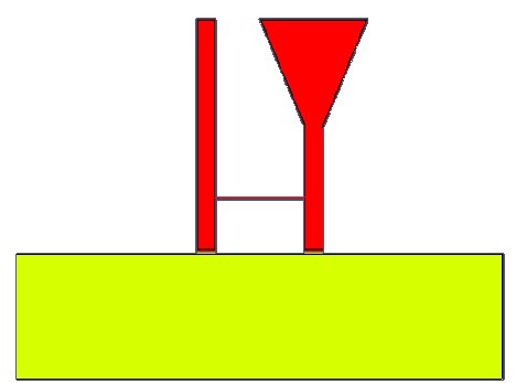
Capillary rise was modeled by numerically solving the Navier-Stokes equations for two incompressible isothermal immiscible Newtonian fluids using the InterFOAM solver in OpenFOAM® [35]. We consider two scenarios: (i) two connected tubes of equal diameter (Figure 8a); and (ii) two connected tubes of equal diameter till 7 mm above fluid level, and then increasing linearly six-fold at 13 mm above fluid level (Figure 8b). The height of the two tubes and the height of fluid above the tube entrance, for both the scenarios, is the same. All tubes are open to the atmosphere and have a constant (atmospheric) pressure boundary. The fluid reservoir is open to the atmosphere, with the top boundary at atmospheric pressure. A high resolution mesh is required to simulate the capillary rise phenomenon. The input parameters are shown in Table 2. The surface tension and contact angle at the air-fluid interface is selected based on the experimental measurement (section 2.1).
| Input parameter | Value |
| Contact angle | 49 |
| Surface tension | 0.0512 N/m |
| Air density | 1 kg/m3 |
| Air viscosity | Pa.s |
| Water density | 1000 kg/m3 |
| Water viscosity | Pa.s |
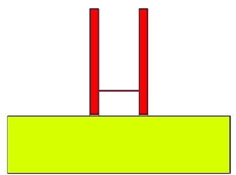
Capillary rise is simulated; the fluid level rises in both tubes and is proportional to the square root of time (Figure 9). Fluid preferentially flows in the connected tube (3 mm above static fluid level) until it is filled, which can be observed by the short-duration departure from the proportional relationship at 3 mm fluid height. Subsequently, the fluid level continues to increase proportional to the square root of time in both tubes for the two-tube model.
The fluid level in the right tube does not increase after 7 mm (above static fluid level) for the tube-vug model, where the tube diameter starts increasing. On the other hand the fluid level in the constant diameter left tube keeps on increasing with time, keeping the same shape as the two-tube model. Deviation between the two models starts at 1.60 seconds, with the fluid level in the tube-vug model rising quicker (Figure 9).
3.3 Micro-tomographic imaging
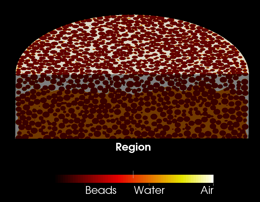
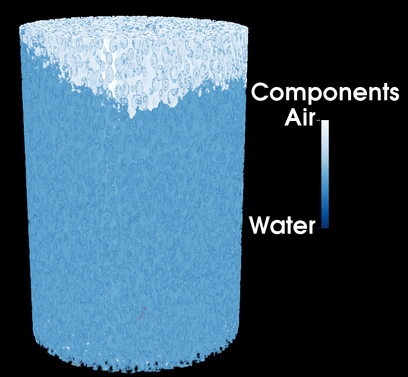
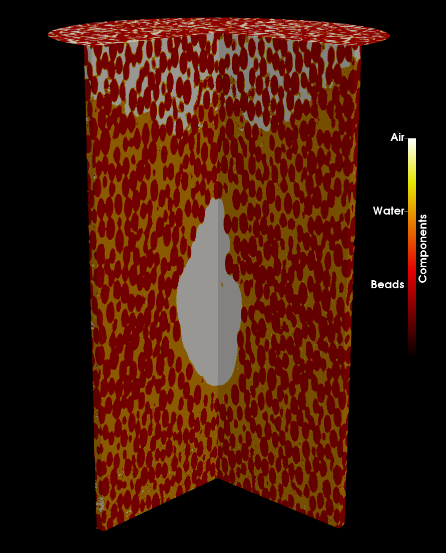
Capillary rise on a homogeneous (HC01) and a vuggy core (VC06) is performed inside the in-house x-ray micro-tomography scanner. Once the fluid front stabilizes, the cores are scanned at a resolution of 25 m to get the spatial fluid distribution inside the core (Figure 10). The scans are segmented to identify the three components: air (white), water (orange), and solid glass (red), and a 3D volume is reconstructed.
The 3D reconstruction of the air-water interface for HC01 is shown in Figure 10a. The air-water interface, at the boundary of the white and orange colors, is fairly uniform across the cross-section with minor variations (less than one bead diameter (1.0 mm)). These variations can be attributed to the local variation in bead packing, and in effect, the pore structure. The air-water interface near the outer surface of the cores has a curvature to it and results in a lower water height at the core boundary.
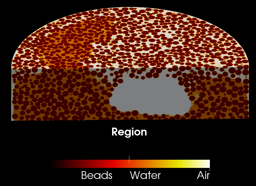
A similar 3D reconstruction of the air-water interface for the vuggy core (VC06) is shown in Figure 10b, where the air-filled vug is colored white. The air-water interface for this core configuration is not uniform across the cross-section with large variations (larger than one bead diameter (1.0 mm)) observed across it. The water level is generally lower near the vug-matrix boundary and the core-atmosphere boundary; the water level increases when it is further away from these boundaries resulting in a higher water level in the matrix with the thicker porous medium. The air-water interface near the outer surface of the core has a curved surface, similar to one observed in HC01, with the water level lower at the core external boundary.
4 Discussion
Combining the above observations, we can clearly see that the presence of disconnected vugs result in a higher capillary rise. The vug acts as a capillary barrier to the imbibing fluid, diverting the fluid to a connected alternative path, which ultimately results in a higher capillary rise.
The capillary rise behavior for all the cores can be split into two zones as discussed in Section 3.1: (i) an initial quick rise; and (ii) an exponential decay. All the cores agree on the rate of initial capillary rise (Figure 11), though the duration for the homogeneous core ( 0.15 seconds) is considerably shorter than the average duration for the vuggy cores ( 0.45 seconds). The similar rate of increase can be explained by the large permeabilities for all the cores which results in a short degassing time (time for air pressure to reduce from atmospheric pressure to zero in the core), on the order of seconds, which is considerably smaller than the duration of initial rise. The initial rise duration for the vuggy cores can be grouped according to their flow unit classification (Figure 5): FU-1 show the longest duration while FU-3 shows the shortest. Permeability difference between the vuggy cores (Table 1) explains the difference in initial rise duration; a better flow quality, i.e. FU-3, starts stabilizing quicker and would therefore have the shortest duration.
Capillary rise at equilibrium is not dependent on the flow unit type (Figures 11). Two generalization can be made: (i) the presence of vug(s) results in a higher capillary rise at equilibrium conditions; and (ii) the highest capillary rise (VC01 and VC10) is in the core with the largest distance to the top of the furthest vug from the bottom. A similar result is also obtained from a CFD simulation (Figure 9), where the fluid attains a higher capillary rise in the connected tube-vug model compared to the two-tube model. We deduce that the momentum of the fluid in the vuggy tube (right tube in Figure 8b) is transferred to the constant diameter tube (left tube in Figure 8a), which pushes the fluid to a greater height and shows the departure from the two-tube model observed in Figure 9a. A higher equilibrium height is also observed in CT scans (Figure 10), which also shows the fluid by-passing the vug and preferentially rising on one side (in an uneven manner).
A point to take into consideration is that the fluid front is not uniform across the cross-section for vuggy core (Figure 12), and for our experiments we have taken the maximum fluid height as the capillary rise value at each timestep. Furthermore, the optical imaging is performed from one side of the core; it is possible that the capillary fluid front might be present at a different height when observed from the backside (Figure 10b).
For most cases, vug(s) impact the capillary rise even before the fluid interacts with them (Figure 7 right). This suggests a feedback mechanism that transmits information of the high permeability ahead, even before the fluid front reaches that point.
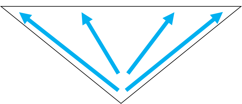
Considering the change in matrix cross-sectional area within the presence of the vug when moving up along the length of the core, the fluid velocity will vary in the matrix (Figure 13). The converging geometry in the matrix, when moving towards the vug, results a higher fluid velocity which results in a jetting movement of the fluid in the upward direction. As soon as the center of the vug is passed, the geometry becomes divergent and the fluid slows down. If the fluid velocity is large enough when it passes the vug, the fluid can completely encapsulate the vug (Figure 14).

5 Summary
In sum, our results suggest that for a carbonate rock in the presence of a disconnected vug, the fluid (contaminant) penetrates deeper in the porous media compared to a homogeneous porous media.The disconnected vugs are not filled and fluid by-passes them as the momentum of the fluid in the capillary leading to the vug is transferred to a capillary that is circumventing the vug, which pushes the fluid to a greater height.The disconnected vugs affect the spontaneous imbibition behavior in a permeable media even before the fluid interacts with them.
Acknowledgments
This project started as part of The University of Texas at Austin Hildebrand Department of Petroleum and Geosystems Engineering (UT PGE) Summer Undergraduate Research Internship (SURI) program and continued under support from Digital Rocks Petrophysics Industrial Affiliates Program (PI Prodanovic).
Nomenclature
| Porosity (%) | |
| Contact angle (°) | |
| Density (g/ml) | |
| CT | Computed tomography |
| DI | De-ionized |
| fps | Frames per second |
| FU | Flow unit |
| HC | Homogeneous core |
| HU | Hounsfield units |
| k | Permeability (D) |
| keV | kilo electron volts |
| NMR | Nuclear Magnetic Resonance |
| R50 | 50th percentaile pore radius (m) |
| VC | Vuggy core |
References
- Folk [1959] Robert L. Folk. Practical Petrographic Classification of Limestones. AAPG Bulletin, 43(1):1–38, 1959. ISSN 0149-1423. URL http://archives.datapages.com/data/bulletns/1957-60/data/pg/0043/0001/0000/0001.htm.
- Murray [1960] Raymond Carl Murray. Origin of porosity in carbonate rocks. Journal of Sedimentary Research, 30(1):59–84, March 1960. ISSN 1527-1404. doi: 10.1306/74D709CA-2B21-11D7-8648000102C1865D. URL https://pubs.geoscienceworld.org/sepm/jsedres/article/30/1/59/95474/origin-of-porosity-in-carbonate-rocks.
- Choquette and Pray [1970] Philip W. Choquette and Lloyd C. Pray. Geologic Nomenclature and Classification of Porosity in Sedimentary Carbonates. AAPG Bulletin, 54(2):207–250, 1970. ISSN 0149-1423. URL http://archives.datapages.com/data/bulletns/1968-70/data/pg/0054/0002/0200/0207.htm.
- Newberry et al. [1996] B. M. Newberry, L. M. Grace, and D. O. Stief. Analysis of Carbonate Dual Porosity Systems from Borehole Electrical Images. Society of Petroleum Engineers, January 1996. ISBN 978-1-55563-434-6. doi: 10.2118/35158-MS. URL https://www.onepetro.org/conference-paper/SPE-35158-MS.
- Ahr et al. [2005] Wayne M Ahr, David Allen, Austin Boyd, H Nate Bachman, Tony Smithson, EA Clerke, KBM Gzara, JK Hassall, CRK Murty, H Zubari, and others. Confronting the carbonate conundrum. Oilfield Review, 17(1):18–29, 2005.
- Schön [2011] J. H. Schön. Chapter 1 - Rocks — Their Classification and General Properties. In J. H. Schön, editor, Handbook of Petroleum Exploration and Production, volume 8 of Physical Properties of Rocks, pages 1–16. Elsevier, January 2011. doi: 10.1016/S1567-8032(11)08001-3. URL http://www.sciencedirect.com/science/article/pii/S1567803211080013.
- Lucia and Loucks [2013] F. Jerry Lucia and Robert G. Loucks. Micropores in Carbonate Mud: Early Development and Petrophysics. 2013. URL http://archives.datapages.com/data/gcags-journal/data/002/002001/pdfs/1.htm.
- Song et al. [2000] Yi-Qiao Song, Seungoh Ryu, and Pabitra N Sen. Determining multiple length scales in rocks. Nature, 406(6792):178–181, 2000.
- Lucia [1995] Jerry Lucia. Rock-Fabric/Petrophysical Classification of Carbonate Pore Space for Reservoir Characterization. AAPG Bulletin, 79, 1995. ISSN 0149-1423. doi: 10.1306/7834D4A4-1721-11D7-8645000102C1865D. URL http://search.datapages.com/data/doi/10.1306/7834D4A4-1721-11D7-8645000102C1865D.
- Zheng [2000] Qing Zheng. Carbonate diagenesis and porosity evolution in the Guelph Formation, southwestern Ontario. PhD thesis, 2000.
- Coniglio et al. [2003] Mario Coniglio, Qing Zheng, and Terry R. Carter. Dolomitization and recrystallization of middle Silurian reefs and platformal carbonates of the Guelph Formation, Michigan Basin, southwestern Ontario. Bulletin of Canadian Petroleum Geology, 51(2):177–199, June 2003. ISSN 0007-4802. doi: 10.2113/51.2.177. URL https://pubs.geoscienceworld.org/cspg/bcpg/article/51/2/177/57879/dolomitization-and-recrystallization-of-middle.
- Akbar et al. [2000] Mahmood Akbar, Badarinadh Vissapragada, Ali H Alghamdi, David Allen, Michael Herron, Andrew Carnegie, Dhruba Dutta, Jean-Rémy Olesen, RD Chourasiya, Dale Logan, Dave Stief, Richard Netherwood, S Duffy Russell, and Kamlesh Saxena. A snapshot of carbonate reservoir evaluation. Oilfield Review, 12(4):20–41, 2000.
- Lucia [1983] F. J. Lucia. Petrophysical Parameters Estimated From Visual Descriptions of Carbonate Rocks: A Field Classification of Carbonate Pore Space. Journal of Petroleum Technology, 35(03):629–637, 1983. ISSN 0149-2136. doi: 10.2118/10073-PA. URL https://www.onepetro.org/journal-paper/SPE-10073-PA.
- Coalson et al. [1994] Edward B. Coalson, Steven M. Goolsby, and Mark H. Franklin. Subtle Seals and Fluid-flow Barriers in Carbonate Rocks. 1994. URL http://archives.datapages.com/data/rmag/UnconSedSeq1994/coalson_b.htm.
- Mehmani et al. [2017] A. Mehmani, S. Kelly, C. Torres-Verdin, and M. Balhoff. Quantification of Fracture-Matrix Fluid Transport in Unconventional Rocks Using Two-Scale Microfluidic Chips. In Unconventional Resources Technology Conference, Austin, Texas, 24-26 July 2017, SEG Global Meeting Abstracts, pages 693–704. Society of Exploration Geophysicists, American Association of Petroleum Geologists, Society of Petroleum Engineers, September 2017. doi: 10.15530/urtec-2017-2669314. URL https://library.seg.org/doi/abs/10.15530/urtec-2017-2669314.
- Lan et al. [2014] Q. Lan, E. Ghanbari, H. Dehghanpour, and R. Hawkes. Water Loss versus Soaking Time: Spontaneous Imbibition in Tight Rocks. Society of Petroleum Engineers, February 2014. ISBN 978-1-61399-294-4. doi: 10.2118/167713-MS. URL https://www.onepetro.org/conference-paper/SPE-167713-MS.
- IAEA [2018] IAEA. Nuclear Power Reactors in the World. 2018. URL http://www-pub.iaea.org/books/IAEABooks/13379/Nuclear-Power-Reactors-in-the-World.
- Zhu and Shaw [2000] Y. G Zhu and G Shaw. Soil contamination with radionuclides and potential remediation. Chemosphere, 41(1):121–128, July 2000. ISSN 0045-6535. doi: 10.1016/S0045-6535(99)00398-7. URL http://www.sciencedirect.com/science/article/pii/S0045653599003987.
- Wan et al. [1996] Jiamin Wan, Tetsu K. Tokunaga, Chin-Fu Tsang, and Gudmundur S. Bodvarsson. Improved Glass Micromodel Methods for Studies of Flow and Transport in Fractured Porous Media. Water Resources Research, 32(7):1955–1964, 1996. ISSN 1944-7973. doi: 10.1029/96WR00755. URL https://agupubs.onlinelibrary.wiley.com/doi/abs/10.1029/96WR00755.
- Wardlaw [1980] Norman C. Wardlaw. The Effects Of Pore Structure On Displacement Efficiency In Reservoir Rocks And In Glass Micromodels. Society of Petroleum Engineers, January 1980. ISBN 978-1-55563-699-9. doi: 10.2118/8843-MS. URL https://www.onepetro.org/conference-paper/SPE-8843-MS.
- Dullien et al. [1986] F. A. L Dullien, Francis S. Y Lai, and I. F MacDonald. Hydraulic continuity of residual wetting phase in porous media. Journal of Colloid and Interface Science, 109(1):201–218, January 1986. ISSN 0021-9797. doi: 10.1016/0021-9797(86)90295-X. URL http://www.sciencedirect.com/science/article/pii/002197978690295X.
- Owete and Brigham [1987] Owete S. Owete and William E. Brigham. Flow Behavior of Foam: A Porous Micromodel Study. SPE Reservoir Engineering, 2(03):315–323, August 1987. ISSN 0885-9248. doi: 10.2118/11349-PA. URL https://www.onepetro.org/journal-paper/SPE-11349-PA.
- Fenwick and Blunt [1998] Darryl H. Fenwick and Martin J. Blunt. Three-dimensional modeling of three phase imbibition and drainage. Advances in Water Resources, 21(2):121–143, March 1998. ISSN 0309-1708. doi: 10.1016/S0309-1708(96)00037-1. URL http://www.sciencedirect.com/science/article/pii/S0309170896000371.
- Khan et al. [2019] Hasan J. Khan, Maša Prodanović, and David A. DiCarlo. The Effect of Vuggy Porosity on Straining in Porous Media. SPE Journal, pages SPE–194201–PA, 2019. ISSN 1086-055X. doi: 10.2118/194201-PA. URL http://www.onepetro.org/doi/10.2118/194201-PA.
- Washburn [1921] Edward W. Washburn. The Dynamics of Capillary Flow. Physical Review, 17(3):273–283, March 1921. doi: 10.1103/PhysRev.17.273. URL https://link.aps.org/doi/10.1103/PhysRev.17.273.
- Khan et al. [2018] Hasan J. Khan, David DiCarlo, and Maša Prodanović. Replicating carbonaceous vug in synthetic porous media. MethodsX, 5:808–811, July 2018. ISSN 2215-0161. doi: 10.1016/j.mex.2018.07.018. URL http://www.sciencedirect.com/science/article/pii/S2215016118301250.
- Otsu [1979] N. Otsu. A Threshold Selection Method from Gray-Level Histograms. IEEE Transactions on Systems, Man, and Cybernetics, 9(1):62–66, January 1979. ISSN 0018-9472. doi: 10.1109/TSMC.1979.4310076.
- Schindelin et al. [2012] Johannes Schindelin, Ignacio Arganda-Carreras, Erwin Frise, Verena Kaynig, Mark Longair, Tobias Pietzsch, Stephan Preibisch, Curtis Rueden, Stephan Saalfeld, Benjamin Schmid, Jean-Yves Tinevez, Daniel James White, Volker Hartenstein, Kevin Eliceiri, Pavel Tomancak, and Albert Cardona. Fiji: an open-source platform for biological-image analysis. Nature Methods, 9(7):676–682, July 2012. ISSN 1548-7091. doi: 10.1038/nmeth.2019. URL http://www.nature.com/nmeth/journal/v9/n7/full/nmeth.2019.html.
- Schneider et al. [2012] Caroline A. Schneider, Wayne S. Rasband, and Kevin W. Eliceiri. NIH Image to ImageJ: 25 years of image analysis. Nature Methods, 9(7):671–675, July 2012. ISSN 1548-7091. doi: 10.1038/nmeth.2089. URL http://www.nature.com/nmeth/journal/v9/n7/full/nmeth.2089.html.
- Pittman [1992] Edward D. Pittman. Relationship of Porosity and Permeability to Various Parameters Derived from Mercury Injection-Capillary Pressure Curves for Sandstone (1). AAPG Bulletin, 76(2):191–198, 1992. ISSN 0149-1423. URL http://archives.datapages.com/data/bulletns/1992-93/data/pg/0076/0002/0000/0191.htm.
- Chopra et al. [1987] A. K. Chopra, M. H. Stein, and J. C. Ader. Development of Reservoir Descriptions To Aid in Design of EOR Projects. Society of Petroleum Engineers, January 1987. ISBN 978-1-55563-596-1. doi: 10.2118/16370-MS. URL https://www.onepetro.org/conference-paper/SPE-16370-MS.
- Fries and Dreyer [2008] N. Fries and M. Dreyer. An analytic solution of capillary rise restrained by gravity. Journal of Colloid and Interface Science, 320(1):259–263, April 2008. ISSN 0021-9797. doi: 10.1016/j.jcis.2008.01.009. URL http://www.sciencedirect.com/science/article/pii/S0021979708000520.
- Gruener et al. [2009] Simon Gruener, Tommy Hofmann, Dirk Wallacher, Andriy V. Kityk, and Patrick Huber. Capillary rise of water in hydrophilic nanopores. Physical Review E, 79(6):067301, June 2009. ISSN 1539-3755, 1550-2376. doi: 10.1103/PhysRevE.79.067301. URL https://link.aps.org/doi/10.1103/PhysRevE.79.067301.
- Gruener et al. [2012] Simon Gruener, Zeinab Sadjadi, Helen E. Hermes, Andriy V. Kityk, Klaus Knorr, Stefan U. Egelhaaf, Heiko Rieger, and Patrick Huber. Anomalous front broadening during spontaneous imbibition in a matrix with elongated pores. Proceedings of the National Academy of Sciences, 109(26):10245–10250, June 2012. ISSN 0027-8424, 1091-6490. doi: 10.1073/pnas.1119352109. URL https://www.pnas.org/content/109/26/10245.
- Weller et al. [1998] Henry G Weller, Gavin Tabor, Hrvoje Jasak, and Christer Fureby. A tensorial approach to computational continuum mechanics using object-oriented techniques. Computers in physics, 12(6):620–631, 1998.
Appendix A Additional experiments
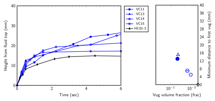
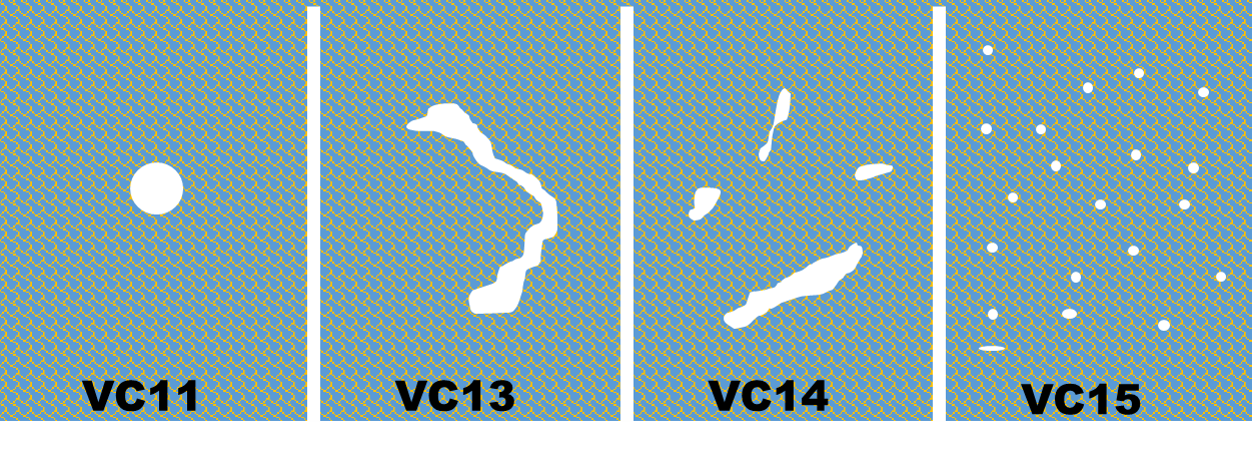
The matrix in the vuggy core is changed by altering the temperature profile (Figure 1a): increasing the peak temperature to 775 C and exposure time to 25 minutes. This results in a matrix porosity of 19.5%. Four new cores with varying different vug configurations (Figure A.1) are fabricated. Petrophysical properties are experimentally determined (Table A.1). When plotted on the porosity-permeability crossplot, these cores align with FU-1 (Figure 5) with k/ = 2103, which is similar to the homogeneous core (HC01) for the previous temperature profile.
| Core No | (%) | (Darcy) | Vug vol. (frac.) | () |
| VC11 | 31.0 | 90 | 0.047 | 127 |
| VC13 | 24.1 | 63 | 0.044 | 132 |
| VC14 | 19.2 | 43 | 0.011 | 129 |
| VC15 | 23.5 | 107 | 0.016 | 188 |
Capillary rise is conducted in the same way (section 3.1) and the results are presented in Figure A.2 along with the capillary rise in one iteration of the homogeneous core (HC01) generated with the previous temperature profile. As observed for the previous cores, the capillary rise is in all the vuggy cores is higher than the rise in the homogeneous core. No discernable pattern is evident when comparing the capillary rise between the two temperature profiles (Figures 7 and A.2).