Thermoelectric properties of tubular nanowires in the presence of a transverse magnetic field
Abstract
We calculate the charge and heat current associate with electrons, generated by a temperature gradient and chemical potential difference between two ends of a tubular nanowire of 30 nm radius in the presence of an external magnetic field perpendicular to its axis. We consider a nanowire based on a semiconductor material, and use the Landauer-Büttiker approach to calculate the transport quantities. We obtain the variation of the Seebeck coefficient (), thermal conductivity (), and the figure of merit (), with respect to the temperature up to 20 K, and with the magnetic field up to 3 T. In particular we show that the Seebeck coefficient can change sign in this domain of parameters. In addition and have oscillations when the magnetic field increases. These oscillations are determined by the energy spectrum of the electrons.
I Introduction
Thermoelectric materials have attracted considerable attention due to their potential applications in electronics (Paulsson and Datta, 2003; Weber et al., 2006; Suarez et al., 2016, 2017), as energy conversion devices (Snyder and Toberer, 2011; Wood, 1988; Fergus, 2012; Nolas et al., 1999; Prete et al., 2019), or as components of complex instruments used in medical science (Cosman, 1990). Thermoelectric devices display interesting properties such as being very reliable because they do not contain any moving part, being of very small size, and most importantly, capable of energy harvesting from waste heat of environment, that makes them very attractive for industry (Dudzinski et al., 2014; Vining, 2009; Snyder and Toberer, 2011). Semiconductor nanowires are promising candidates for thermoelectric applications, along with their rich and complex electrical, optical, and photovoltaics properties (Zhao et al., 2004; Kateb et al., 2013, 2016; Tian et al., 2009). Nanowires have played an important role in this research direction due to their ability to provide efficient thermoelectric elements with low thermal conductivity and high figure of merit () (Rossella et al., 2018; Hong et al., 2020; Díez et al., 2020).
In particular, core-shell nanowires based on III-V semiconductors enable the control of charge, and possibly heat transfer through the specific geometry and shell thickness. With a doped shell and undoped core one can obtain a tubular conductor Gül et al. (2014) with conduction electrons captured inside the shell. Most often such nanowires have a hexagonal cross section and the charge density peaks at the shell corners (Ferrari et al., 2009; Sitek et al., 2016, 2015; Torres et al., 2018; Fust et al., 2020). A nanowire made of a single material, for example InAs, may also become a tubular conductor if the conduction electrons are pushed towards the nanowire walls due to a favorable band bending at the surface Heedt et al. (2016). Assuming a tubular distribution of the electrons in the nanowire, another localization mechanism, that we focus on in is paper, is produced by a magnetic field perpendicular to the nanowire axis, and in that case the electron density within the shell increases in the direction perpendicular to the field, where the so called snaking states are formed Manolescu et al. (2013); Rosdahl et al. (2015); Manolescu et al. (2016); Chang and Ortix (2016).
In a recent paper where two of the present authors where involved, it has been predicted theoretically that a temperature gradient can lead to reversal of thermoelectric current in tubular nanowires in the presence of transverse magnetic field, at low temperatures Erlingsson et al. (2017), meaning that the electrons can either flow from the hot to the cold lead, or vice versa. This prediction indicates the importance of the magnetic field effect on the thermoelectric properties of a tubular conductor, but it still awaits an experimental validation.
In the present paper we want to address, still theoretically, the efficiency of a thermoelectric element based on a tubular conductor in a perpendicular magnetic field. Efficient thermoelectric devices are supposed to produce a considerable electric current, but at the same time to limit the heat flow (Boukai et al., 2008; Mingo, 2004). These characteristics are incorporated in the dimensionless figure of merit , which is defined as
| (1) |
where is the Seebeck coefficient, is the electrical conductivity, the thermal conductivity, and the temperature. Hence, there are several parameters that need to be optimized to reach maximum value of . In our physical system we know that the the thermoelectric current is a nontrivial function of the magnetic field and temperature Erlingsson et al. (2017), and the first step of the present paper will be to obtain the Seebeck coefficient. After that, we will look at the thermal conductivity and finally at .
The thermal conductivity reported for crystalline nanowires is more than two orders of magnitude lower than the bulk values (Li et al., 2003). Also, the phonon scattering at the nanowire surface substantially reduces their thermal conductivity and increases the thermoelectric power factor () (Wu et al., 2013). The diversity of fabrication methods for introducing dopants or impurities into the lattice is another reason that makes the semiconductor nanowires important for their thermoelectric characteristics (Pennelli et al., 2018; Erlingsson et al., 2018; Domínguez-Adame et al., 2019; Vuttivorakulchai et al., 2018; Thorgilsson et al., 2017). The thermal transport in nanoscale systems, whose dimension is much smaller than the mean free path of electrons, cannot be explained by a simple law due to the presence of quantum-mechanical features and strong non-linear behavior (Cahill et al., 2003). At intermediate temperatures where ballistic and diffusive phonons coexist, the thermal conductance decreases non-linearly with the length. And especially at low frequency, where the acoustic phonons give the major contribution to the thermal conductance (Yadav et al., 2006). But at low temperatures charge carriers have an important role in thermal transport quantized in multiples of the universal value , also electrical conductance is quantized in multiples of universal value which can be understood within Landauer´s formula (Yamamoto et al., 2004; Yamamoto and Watanabe, 2006).
It has been shown that a magnetic field produces large changes in the thermoelectric properties, including the reduction of thermal conductivity of charge carriers (Wolfe and Smith, 1962). This has been demonstrated experimentally for Bi88Sb12 at 78–295 K and magnetic fields up to 1.7 T. The magnetic field has been also studied for GaAs-Ga1-xAlxAs heterojunction up to 20 T (Fletcher et al., 1986). The results showed an oscillatory behavior of thermopower () with the applied magnetic field. The magnetic field has been also studied for Bi nanowires array at 50–300 K which showed there is an optimum magnetic field for power factor (Hasegawa et al., 2005).
The material of the paper is structured in these steps: In Section 2 we present the model and the energy spectra of our system, the tubular conductor in perpendicular magnetic field. Then, in Section 3 we discuss and show the results for the Seebeck coefficient, for the thermal conductivity, and for the figure of merit. Finally, the conclusions are collected in Section 4.
II Model and methods
In this paper, we consider electronic transport in a tubular, cylindrical nanowire, in the presence of a longitudinal temperature difference and a uniform magnetic field transverse to the axis of the cylinder. The conduction takes place only in a narrow shell at the surface and not through the bulk (Heedt et al., 2016).
The Hamiltonian of the system can be written as
| (2) |
where is the magnetic field in the direction, i.e. perpendicular to the nanowire length which is oriented along the axis, and is the corresponding vector potential. Also, is the electron charge, and are the effective electron mass and bulk g-factor of InAs, is the Bohr’s magneton and is the spin label. We chose the effective mass and g-factor as for InAs because this is a relatively common material used for core-shell nanowires. We assume that electrons propagate along the nanowire without interacting with other electrons.
System parameters are nm, T and also by considering material parameter for InAs, we can calculate the heat current and electrical current driven by the temperature bias and chemical potential difference between the two ends of the nanowire, where we assume external leads are contacted. We calculate the charge current and heat current through the nanowire using the Landauer approach:
| (3) |
| (4) |
where is the transmission function, and
is the Fermi function for the left (L) or right (R) reservoir with chemical potential and temperature . We consider a temperature bias , with always fixed at K, and a chemical potential bias , with and , where is fixed at meV and is varied between meV.
Ballistic transport of electrons in nanowires leads to a transmission , as a function of energy, with a step behavior. Nanowires showing such step-like behaviour have been measured, and in the presence of a low, but achievable impurity density the steps are still visible (Kammhuber et al., 2016). Based on this experimental fact we assume ballistic transport in our system. The transmission function in the presence of impurities can be obtained with the recursive Green’s function method (Ferry and Goodnick, 1999; Erlingsson et al., 2017). For nanowires with inhomogeneities, such as impurities, a nonuniform diameter, surface changes, or stacking faults, the conductance becomes a series of transmission resonances due to quantum dot like states (Wu et al., 2013). In that case transport calculations based on elastic scattering have been performed up to 24 K, so we can neglect inelastic collisions in our temperature range (Wu et al., 2013; Erlingsson et al., 2017, 2018).
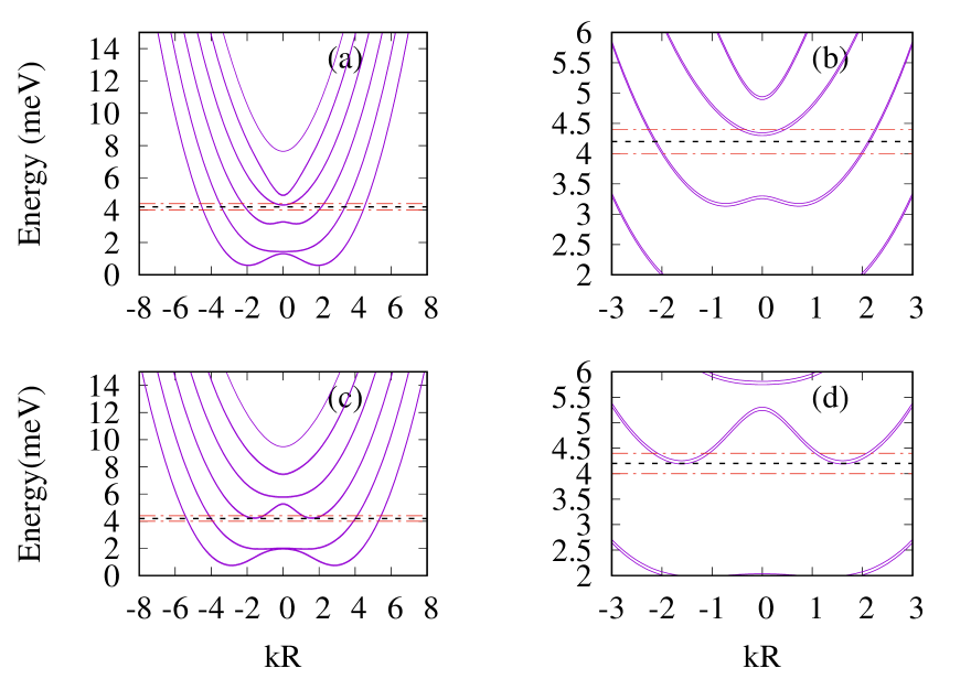
The eigenstates of the Hamiltonian (2) are calculated by numerical diagonalization in a basis set corresponding to plane waves , with the wave vector in the longitudinal direction, and angular momentum eigenfunction , with , in the transversal plane where the electrons are confined on a circle of radius Manolescu et al. (2013). The resulting energy spectra for magnetic fields T and 2.5 T are shown in Fig. 1. These spectra have an interesting feature: they may not always monotonic functions of when it has a fixed sign. Meaning that the transport channels, i.e. the number of states with a fixed energy, which in general increases with increasing the energy, in this case may also decrease. Consequently, the thermoelectric current may change sign Erlingsson et al. (2017).
In the transport calculations we will consider that only electrons that are close to in energy contribute to the heat transport. The chemical potentials are chosen such that is close to a subband bottom. In Fig. 1 (b) and (d) we show this energy interval for two values of the magnetic field.
III Results and discussion
III.1 Seebeck coefficient
The Seebeck coefficient or the thermopower, , is defined by the ratio , where the voltage difference is produced in presence of a small temperature difference between two points of a conductor, under an open circuit condition. Usually the thermopower consists of two additive contributions: diffusion , and phonon drag . The first one originates from the diffusion of carriers (electrons or holes) and second one comes from the momentum that is transferred to carriers via their coupling to non-equilibrium acoustic phonons in the presence of a temperature gradient (Tsaousidou, 2010a; Fletcher et al., 1997, 1994). For the total thermopower there is a very good agreement between theory and experiments at temperature below K for example in bulk silicon (Behnen, 1990). However, at this low temperatures, where normally dominates, we can neglect the phonon drag contribution to the non-equilibrium electron distribution function, and consider elastic scattering as the main mechanism that limits the electrons’ momentum relaxation time.
The Seebeck coefficient is important for two reasons. First, this coefficient provides fundamental information about the electronic energy structure and the electron scattering mechanism in a system. Second, there is some evidence suggesting that thermoelectric energy conversion can be more efficient in low-dimensional systems (Tsaousidou, 2010b). For example, for a semiconductor, a large magnitude of Seebeck coefficient requires only one type of carrier, because mixed n-type and p-type conduction will send both carriers through contacts, leading to a reduced Seebeck voltage. The relation between the carrier concentration and Seebeck coefficient, for bulk states, is given by:
| (5) |
where is the carrier concentration and is the effective mass of carriers. Although a low carrier concentration of insulators and semiconductors result in large Seebeck coefficient, it also leads to a low electrical conductivity, , where the electrical conductivity and electrical resistivity are related to through the carrier mobility (Snyder and Toberer, 2011; Hicks and Dresselhaus, 1993; Rowe, 2018). There is also another conflict with the effective mass of the charge carriers, in a manner that large effective mass provide high thermopower but low electrical conductivity.
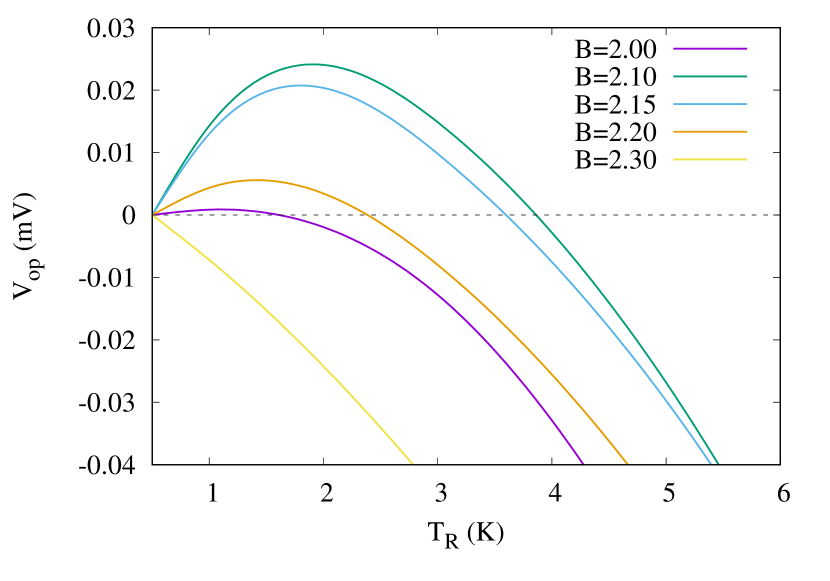
In the present work we consider ballistic transport such that the electronic energy spectra have the main role in the behavior of the thermopower. We assume that the scattering due to impurities have negligible effects, and that is a reasonable approximation in a sufficiently clean system Thorgilsson et al. (2017); Erlingsson et al. (2018). Using the transmission functions for the calculated energy spectra we determine the voltage in an open circuit condition, , from the chemical potential bias necessary to bring to zero the electric current in the system [Eq. (3)]. That means we evaluate as a function of the temperature of the right lead, for different values of magnetic field. As one can see in Fig. 2 the open circuit voltage has a nonlinear dependence on the temperature bias, for magnetic fields between T. More remarkably is though the change of sign as a function of the temperature, which occurs because of the nonmonotonic variation of the transmission function with respect to the energy Erlingsson et al. (2017).
We obtain numerically the Seebeck coefficient, , as the linear coefficient of as function of the temperature gradient, , by performing the procedure described above with a small temperature bias, K. This time both and are varied. We calculate the Seebeck coefficient at the specific situated close to a subband minimum, where the insensitivity of to the energy dependence of electron relaxation time has a direct impact on the phonon-drag contribution to the magnetothermopower tensor, that results in becomes dominating over .
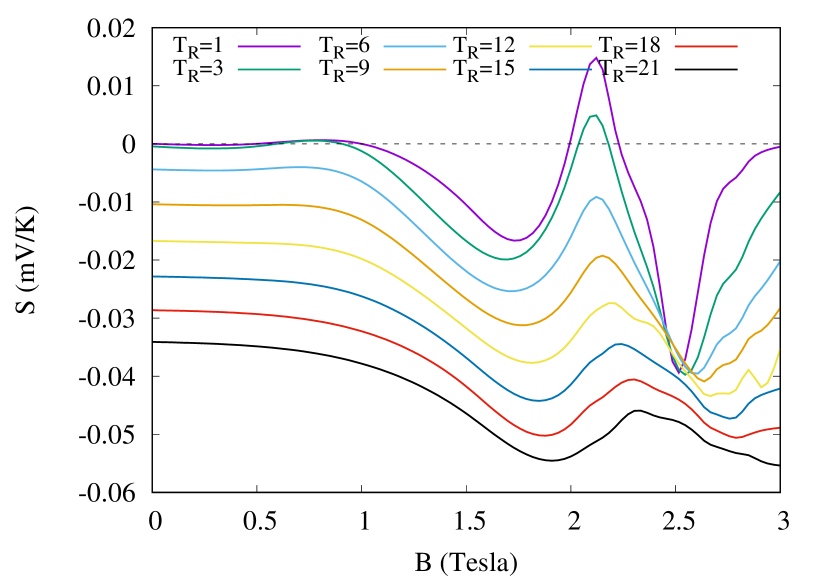
Fig. 3 shows the variation of with the magnetic field at different temperatures . It can be clearly seen that starts with nearly a constant value, and then continues with an oscillatory behavior, with increasing magnetic field, for all studied here. The amplitude of oscillation becomes smaller at higher . An oscillatory behavior with respect to magnetic field has been obtained earlier in the 2D electron gas, in the fractional quantum Hall regime, but without a sign change (Fletcher et al., 1986). Oscillations of the thermopower vs. the chemical potential with sign changes were predicted a long time ago for quantum dots Beenakker and Staring (1992), and confirmed experimentally Svensson et al. (2012), but as a consequence of isolated resonances. Besides, at low fields, i.e. in the constant regime of , it has been shown that the increase of the temperature gradient increases , and that is in agreement with our results. Indeed, at low temperatures (1–6 K) and magnetic field above 2 T our oscillations and the sign change of the thermopower are expected from the similar behavior of the thermoelectric current and open circuit voltage discussed above. And at higher temperatures the oscillations become smoother and without a sign change.
III.2 Thermal conductivity
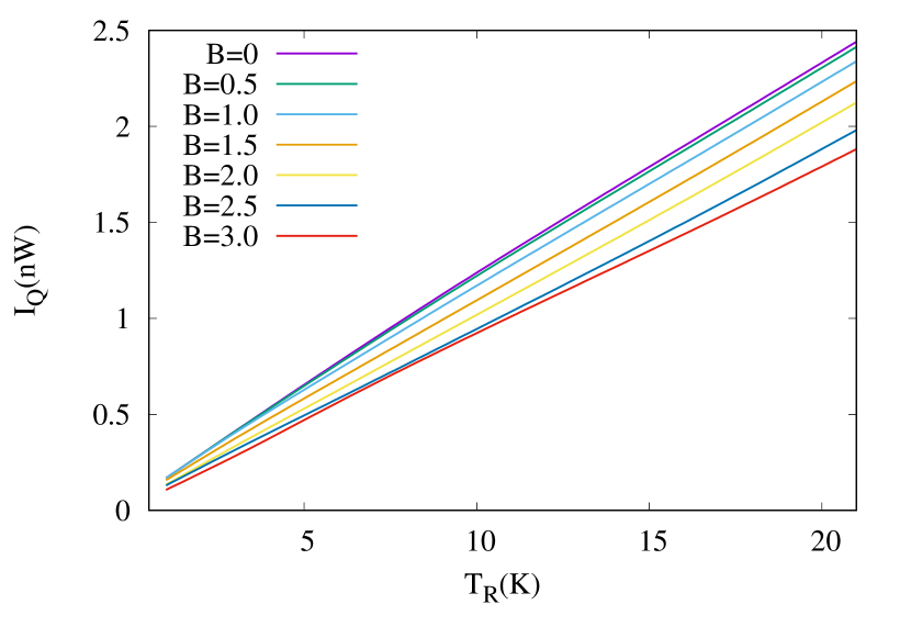
One of the fundamental factors for high efficient thermoelectric conversion is the thermal conductivity, which needs to be minimized. There are many possibilities to reduce the thermal conductance of a nanosystem (Li et al., 2003). Our next step is to evaluate the heat transported by the electrons of our system, which accompany the transport of electric charge. We calculate the heat current as function of the temperature of the right lead, for different values of the magnetic field, using Eq. (4), and . We can see in Fig. 4 that with increasing the magnetic field strength, the heat current decreases, but not dramatically. Also, the heat current is more influenced by the magnetic field at high temperatures, for example at K compared to K. The reason of this behavior is the distribution of carriers over the energy states such that more electrons are localized due to the closed cyclotron motion imposed by the field, and fewer of them are available for transport. Note also that the heat current does not change sign, as the charge current does, that is in agreement with the second law of thermodynamics.
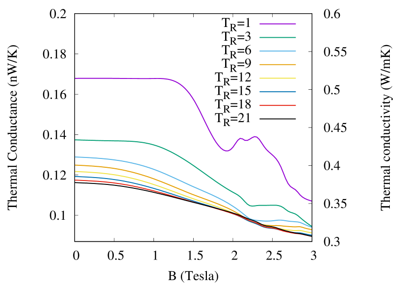
The thermal conductance, , and thermal conductivity, , as functions of the magnetic field, for different temperatures of the right lead, are shown in Fig. 5. Here we use the whole cross sectional area of the cylinder, although the transport of both heat and charge occurs through the shell defined by the outer surface. The full cross sectional area is however relevant if the core is also included in the heat transport with phonons, which are neglected at our low temperatures.
The figure clearly indicates two regions with (i) constant and at low fields and (ii) a non-linear reduction at higher applied magnetic field. We can see almost the same trend for (or ) for different temperatures, but that is more evident at lower . It is obvious that the increase of the magnetic field leads to a reduction of the thermal conductance and thermal conductivity, but the amount of these changes are different for each temperature. The reduction of the contributions of charge carriers (electrons or holes) to the thermal conductivity has been observed in experimental studies for both bulk and nanowire arrays (Wolfe and Smith, 1962; Hasegawa et al., 2005).
III.3 Figure of merit
Next, in order to find the optimum conditions for thermoelectric conversion, we need to calculate using Eq. (1). High electrical conductivity and low thermal conductivity is required to maximize or optimize , that is achievable by considering lattice thermal conductance and materials characteristics (Dresselhaus et al., 2007; Chen et al., 2003; Rosi, 1968). In formula the cross sectional area of the full cylinder () used in the thermal conductivity is going to be compensate by the area used in electrical conductivity. Electrical conductivity calculated from , where for each specific temperature and magnetic field several values of and were calculated separately and got differentiated. Fig. 6 represents as function of magnetic field for different temperatures of the right contact.
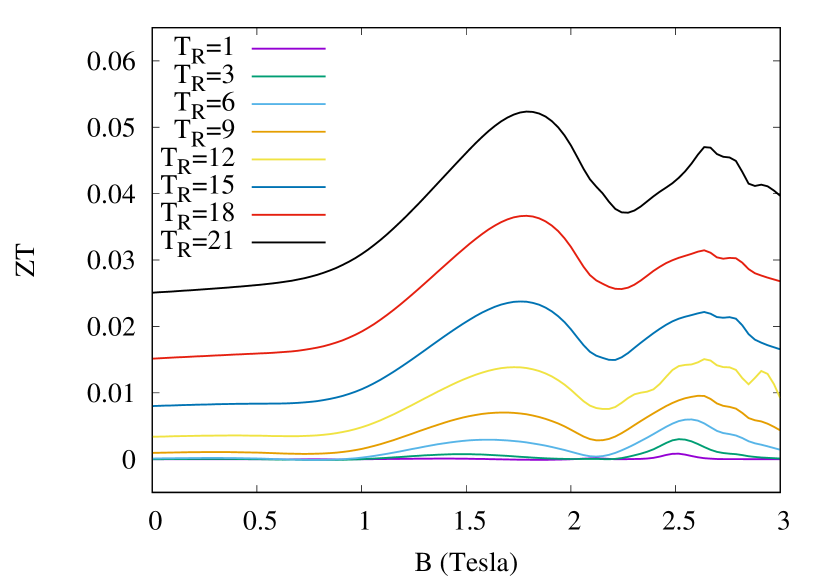
Again, the figure shows two regions, of constant and oscillating , respectively. It is also clear that increasing the temperature shifts to higher values, in both regions, non-linearly. Also, at low temperatures, the figure of merit shows limited changes with increasing magnetic field, but for temperatures more than 9 K we have some obvious variation of values. There are two peaks for in the figure, which is a specific result of magnetic field presence. At all temperatures studied here, the peaks are located at about T and 2.5 T with a slight shift to higher field at higher temperature. Thus, regardless of the temperature difference, there is an optimum magnetic field that leads to maximum . In addition, although we are referring to low temperatures, doubling the value of just by applying to the system an external magnetic field is interesting tuning possibility.
With increasing the temperature above 20 K, one would expect an increase of simply because of the temperature factor in the definition, Eq. (1). But, of course, the phononic contribution to the heat transport increases with temperature, and the phonon drag and lattice vibrations will end up by dominating over the diffusive heat transport due to electrons. However, experimental values for the thermal conductivity in nanowires with diameters between 20-100 nm shows a saturation behavior for temperatures above 100 K to values like 10-40 W/mK (Li et al., 2003). Therefore, for such a temperature we can expect the figure of merit of our system to become roughly ten times bigger than the values shown in Fig. 6.
IV Conclusions
In this paper we have calculated the most important thermoelectric parameters, such as heat and electric current, the open circuit voltage , Seebeck coefficient , thermal conductivity , and figure of merit , produced by electrons confined within a tubular nanowire due to a temperature bias, in presence of transverse magnetic field. To this end, heat current and electrical current variations are obtained in the temperature range between ( K). Increasing the magnetic field leads to reduction in thermal conductivity, which is more pronounced at lower temperatures. The energy spectrum of electrons is a nonmonotonic function of the wave vector along the nanowire, and so is the transmission function with respect to the energy. Consequently can change sign when the temperature gradient or the magnetic field increase. Both and have a constant to oscillatory transition with increasing the magnetic field. For example for a cylinder radius of 30 nm, presents two peaks at about 1.8 and 2.5 T which are independent of the temperature.
These feature allow a substantial tuning of the thermoelectric response of the nanowire with changing the temperature or with applying an external magnetic field. To the best of our knowledge, although several groups have performed thermoelectric measurements of nanowires at low temperatures Prete et al. (2019); Díez et al. (2020); Fust et al. (2020); Li et al. (2003); Wu et al. (2013); Pennelli et al. (2018), experimental investigations of tubular conductors based on core-shell geometry in a transverse magnetic field have not been reported yet. Therefore it is our hope that our theoretical results will stimulate such an experimental work.
Acknowledgements.
This work was supported by the Icelandic Research Fund, Grant 195943-051.References
- Paulsson and Datta (2003) M. Paulsson and S. Datta, Physical Review B 67, 241403 (2003).
- Weber et al. (2006) J. Weber, K. Potje-Kamloth, F. Haase, P. Detemple, F. Völklein, and T. Doll, Sensors and Actuators A: Physical 132, 325 (2006).
- Suarez et al. (2016) F. Suarez, A. Nozariasbmarz, D. Vashaee, and M. C. Öztürk, Energy & Environmental Science 9, 2099 (2016).
- Suarez et al. (2017) F. Suarez, D. P. Parekh, C. Ladd, D. Vashaee, M. D. Dickey, and M. C. Öztürk, Applied energy 202, 736 (2017).
- Snyder and Toberer (2011) G. J. Snyder and E. S. Toberer, in materials for sustainable energy: a collection of peer-reviewed research and review articles from Nature Publishing Group (World Scientific, 2011) pp. 101–110.
- Wood (1988) C. Wood, Reports on progress in physics 51, 459 (1988).
- Fergus (2012) J. W. Fergus, Journal of the European Ceramic Society 32, 525 (2012).
- Nolas et al. (1999) G. Nolas, D. Morelli, and T. M. Tritt, Annual Review of Materials Science 29, 89 (1999).
- Prete et al. (2019) D. Prete, P. A. Erdman, V. Demontis, V. Zannier, D. Ercolani, L. Sorba, F. Beltram, F. Rossella, F. Taddei, and S. Roddaro, Nano letters 19, 3033 (2019).
- Cosman (1990) E. R. Cosman, “Thermometric cardiac tissue ablation electrode with ultra-sensitive temperature detection,” (1990), US Patent 4,966,597.
- Dudzinski et al. (2014) L. Dudzinski, J. Hamley, P. McCallum, C. Sandifer, T. J. Sutliff, and J. F. Zakrajsek, in 12th International Energy Conversion Engineering Conference (2014) p. 3462.
- Vining (2009) C. B. Vining, Nature materials 8, 83 (2009).
- Zhao et al. (2004) X. Zhao, C. Wei, L. Yang, and M. Chou, Physical review letters 92, 236805 (2004).
- Kateb et al. (2013) M. Kateb, V. Ahmadi, and M. Mohseni, Solar energy materials and solar cells 112, 57 (2013).
- Kateb et al. (2016) M. Kateb, S. Safarian, M. Kolahdouz, M. Fathipour, and V. Ahamdi, Solar Energy Materials and Solar Cells 145, 200 (2016).
- Tian et al. (2009) B. Tian, T. J. Kempa, and C. M. Lieber, Chemical Society Reviews 38, 16 (2009).
- Rossella et al. (2018) F. Rossella, G. Pennelli, and S. Roddaro, in Semiconductors and Semimetals, Vol. 98 (Elsevier, 2018) pp. 409–444.
- Hong et al. (2020) M. Hong, W. Lyu, Y. Wang, J. Zou, and Z.-G. Chen, Journal of the American Chemical Society (2020).
- Díez et al. (2020) G. G. Díez, J. M. S. Gordillo, M. P. Pujadó, M. Salleras, L. Fonseca, A. Morata, and A. T. Rubio, Nano Energy 67, 104191 (2020).
- Gül et al. (2014) O. Gül, N. Demarina, C. Blömers, T. Rieger, H. Lüth, M. I. Lepsa, D. Grützmacher, and T. Schäpers, Phys. Rev. B 89, 045417 (2014).
- Ferrari et al. (2009) G. Ferrari, G. Goldoni, A. Bertoni, G. Cuoghi, and E. Molinari, Nano Letters 9, 1631 (2009).
- Sitek et al. (2016) A. Sitek, G. Thorgilsson, V. Gudmundsson, and A. Manolescu, Nanotechnology 27, 225202 (2016).
- Sitek et al. (2015) A. Sitek, L. Serra, V. Gudmundsson, and A. Manolescu, Physical Review B 91, 235429 (2015).
- Torres et al. (2018) M. U. Torres, A. Sitek, S. I. Erlingsson, G. Thorgilsson, V. Gudmundsson, and A. Manolescu, Physical Review B 98, 085419 (2018).
- Fust et al. (2020) S. Fust, A. Faustmann, D. J. Carrad, J. Bissinger, B. Loitsch, M. Döblinger, J. Becker, G. Abstreiter, J. J. Finley, and G. Koblmüller, Advanced Materials 32, 1905458 (2020).
- Heedt et al. (2016) S. Heedt, A. Manolescu, G. Nemnes, W. Prost, J. Schubert, D. Grutzmacher, and T. Schäpers, Nano letters 16, 4569 (2016).
- Manolescu et al. (2013) A. Manolescu, T. Rosdahl, S. I. Erlingsson, L. Serra, and V. Gudmundsson, The European Physical Journal B 86, 445 (2013).
- Rosdahl et al. (2015) T. O. Rosdahl, A. Manolescu, and V. Gudmundsson, Nano Letters 15, 254 (2015).
- Manolescu et al. (2016) A. Manolescu, G. A. Nemnes, A. Sitek, T. O. Rosdahl, S. I. Erlingsson, and V. Gudmundsson, Physical Review B 93, 205445 (2016).
- Chang and Ortix (2016) C.-H. Chang and C. Ortix, International Journal of Modern Physics B 30, 1630016 (2016).
- Erlingsson et al. (2017) S. I. Erlingsson, A. Manolescu, G. A. Nemnes, J. H. Bardarson, and D. Sanchez, Physical review letters 119, 036804 (2017).
- Boukai et al. (2008) A. I. Boukai, Y. Bunimovich, J. Tahir-Kheli, J.-K. Yu, W. A. Goddard Iii, and J. R. Heath, Nature 451, 168 (2008).
- Mingo (2004) N. Mingo, Applied Physics Letters 84, 2652 (2004).
- Li et al. (2003) D. Li, Y. Wu, P. Kim, L. Shi, P. Yang, and A. Majumdar, Applied Physics Letters 83, 2934 (2003).
- Wu et al. (2013) P. M. Wu, J. Gooth, X. Zianni, S. F. Svensson, J. G. Gluschke, K. A. Dick, C. Thelander, K. Nielsch, and H. Linke, Nano letters 13, 4080 (2013).
- Pennelli et al. (2018) G. Pennelli, S. Elyamny, and E. Dimaggio, Nanotechnology 29, 505402 (2018).
- Erlingsson et al. (2018) S. I. Erlingsson, J. H. Bardarson, and A. Manolescu, Beilstein journal of nanotechnology 9, 1156 (2018).
- Domínguez-Adame et al. (2019) F. Domínguez-Adame, M. Martín-González, D. Sánchez, and A. Cantarero, Physica E: Low-dimensional Systems and Nanostructures (2019).
- Vuttivorakulchai et al. (2018) K. Vuttivorakulchai, M. Luisier, and A. Schenk, Journal of Applied Physics 124, 205101 (2018).
- Thorgilsson et al. (2017) G. Thorgilsson, S. I. Erlingsson, and A. Manolescu, Journal of Physics: Conference Series 906, 012021 (2017).
- Cahill et al. (2003) D. G. Cahill, W. K. Ford, K. E. Goodson, G. D. Mahan, A. Majumdar, H. J. Maris, R. Merlin, and S. R. Phillpot, Journal of applied physics 93, 793 (2003).
- Yadav et al. (2006) H. K. Yadav, V. Gupta, K. Sreenivas, S. Singh, B. Sundarakannan, and R. Katiyar, Physical review letters 97, 085502 (2006).
- Yamamoto et al. (2004) T. Yamamoto, S. Watanabe, and K. Watanabe, Physical review letters 92, 075502 (2004).
- Yamamoto and Watanabe (2006) T. Yamamoto and K. Watanabe, Physical review letters 96, 255503 (2006).
- Wolfe and Smith (1962) R. Wolfe and G. Smith, Applied Physics Letters 1, 5 (1962).
- Fletcher et al. (1986) R. Fletcher, J. Maan, K. Ploog, and G. Weimann, Physical Review B 33, 7122 (1986).
- Hasegawa et al. (2005) Y. Hasegawa, Y. Ishikawa, H. Morita, T. Komine, H. Shirai, and H. Nakamura, Journal of applied physics 97, 083907 (2005).
- Kammhuber et al. (2016) J. Kammhuber, M. C. Cassidy, H. Zhang, O. Gül, F. Pei, M. W. de Moor, B. Nijholt, K. Watanabe, T. Taniguchi, D. Car, et al., Nano letters 16, 3482 (2016).
- Ferry and Goodnick (1999) D. Ferry and S. M. Goodnick, Transport in nanostructures, 6 (Cambridge university press, 1999).
- Tsaousidou (2010a) M. Tsaousidou, Frontiers in Nanoscience and nanotechnology 2, 477 (2010a).
- Fletcher et al. (1997) R. Fletcher, V. Pudalov, Y. Feng, M. Tsaousidou, and P. Butcher, Physical Review B 56, 12422 (1997).
- Fletcher et al. (1994) R. Fletcher, J. Harris, C. Foxon, M. Tsaousidou, and P. Butcher, Physical Review B 50, 14991 (1994).
- Behnen (1990) E. Behnen, Journal of applied physics 67, 287 (1990).
- Tsaousidou (2010b) M. Tsaousidou, Frontiers in Nanoscience and nanotechnology 2, 477 (2010b).
- Hicks and Dresselhaus (1993) L. Hicks and M. S. Dresselhaus, Physical review B 47, 16631 (1993).
- Rowe (2018) D. M. Rowe, CRC handbook of thermoelectrics (CRC press, 2018).
- Beenakker and Staring (1992) C. W. J. Beenakker and A. A. M. Staring, Phys. Rev. B 46, 9667 (1992).
- Svensson et al. (2012) S. Svensson, A. Persson, E. Hoffmann, N. Nakpathomkun, H. Nilsson, H. Xu, L. Samuelson, and H. Linke, New Journal of Physics 14, 033041 (2012).
- Dresselhaus et al. (2007) M. S. Dresselhaus, G. Chen, M. Y. Tang, R. Yang, H. Lee, D. Wang, Z. Ren, J.-P. Fleurial, and P. Gogna, Advanced materials 19, 1043 (2007).
- Chen et al. (2003) G. Chen, M. Dresselhaus, G. Dresselhaus, J.-P. Fleurial, and T. Caillat, International materials reviews 48, 45 (2003).
- Rosi (1968) F. Rosi, Solid-State Electronics 11, 833 (1968).