Interpreting Holographic Molecular Binding Assays with Effective Medium Theory
Abstract
Holographic molecular binding assays use holographic video microscopy to directly detect molecules binding to the surfaces of micrometer-scale colloidal beads by monitoring associated changes in the beads’ light-scattering properties. Holograms of individual spheres are analyzed by fitting to a generative model based on the Lorenz-Mie theory of light scattering. Each fit yields an estimate of a probe bead’s diameter and refractive index with sufficient precision to watch the beads grow as molecules bind. Rather than modeling the molecular-scale coating, however, these fits use effective medium theory, treating the coated sphere as if it were homogeneous. This effective-sphere analysis is rapid and numerically robust and so is useful for practical implementations of label-free immunoassays. Here, we assess how effective-sphere properties reflect the properties of molecular-scale coatings by modeling coated spheres with the discrete-dipole approximation and analyzing their holograms with the effective-sphere model.
I Introduction
Holographic particle characterization works by recording the in-line hologram of a colloidal particle sheng_digital_2006 and then analyzing it pixel-by-pixel lee_characterizing_2007 with a generative model based on the Lorenz-Mie theory of light scattering bohren_absorption_1983 ; mishchenko_scattering_2002 ; gouesbet_generalized_2011 . This analysis yields the particle’s diameter with nanometer-scale precision and its refractive index to within a part per thousand lee_characterizing_2007 ; krishnatreya_measuring_2014 , which should be fine enough to detect nanometer-scale molecules binding to the surfaces of micrometer-scale colloidal beads cheong_flow_2009 ; zagzag_holographic_2020 . The resulting label-free assay for molecular binding, shown schematically in Fig. 1(a), has immediate applications for medical diagnostics, a proof-of-concept immunoassay based on holographic particle characterization having recently been reported zagzag_holographic_2020 . Holographic molecular binding assays currently are being developed into diagnostic and serological tests for infection by SARS-CoV-2, the virus responsible for COVID-19.
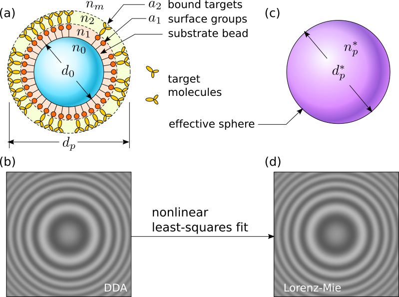
Practical implementations of holographic molecular binding assays rely on the effective-sphere model cheong_flow_2009 ; hannel_holographic_2015 ; wang_holographic_2016 ; wang_holographic_2016-1 ; fung_computational_2019 ; odete_role_2020 , which treats the scatterer as a homogeneous isotropic sphere regardless of its actual composition and microstructure. Values obtained for the particle’s diameter and refractive index then are interpreted to be characteristics of an effective sphere whose properties represent averages over the particle’s inhomogeneities using Maxwell Garnett effective-medium theory markel_introduction_2016 .
The effective-sphere model has been validated through studies on porous spheres cheong_holographic_2011 ; odete_role_2020 and fractal colloidal clusters wang_holographic_2016 ; wang_holographic_2016-1 ; cheong_holographic_2017 ; fung_computational_2019 . In both cases, the two phases that make up the particle are distributed uniformly, which is consistent with the assumptions underlying Maxwell Garnett theory. The heterogeneity in bead-based molecular binding assays, by contrast, is restricted to thin surface layers. The present study assesses how properties of coated spheres estimated with the effective-sphere model reflect the presence and composition of the surface layers with the goal of guiding the development of fast and effective holographic molecular binding assays.
We appraise the effective-sphere analysis of coated beads by using it to analyze synthetic holograms computed with the discrete-dipole approximation (DDA) draine_discrete-dipole_1994 . Direct comparisons between ground truth values and fits to the effective-sphere model demonstrate that effective-sphere analysis usefully characterizes coated spheres, reliably detecting the presence of coatings and offering insights into their properties. The results of this study are consistent with trends in bead diameter and refractive index reported in experimental demonstrations of holographic molecular binding assays. This positive outcome furthermore means that molecular binding assays based on holographic particle characterization can benefit from the speed and robustness of effective-sphere analysis.
I.1 Holographic particle characterization
The holograms used for holographic particle characterization are recorded by illuminating a colloidal dispersion with a collimated laser beam sheng_digital_2006 ; lee_characterizing_2007 . Light scattered by a colloidal particle interferes with the remainder of the beam in the focal plane of a microscope that magnifies the interference pattern and relays it to a video camera. Each magnified intensity pattern recorded by the camera is a hologram of the particles in the observation volume and encodes information on their three-dimensional positions, as well as their sizes, shapes and compositions.
Holographic particle characterization extracts information from recorded holograms by fitting to a generative model for the image-formation process lee_characterizing_2007 . A standard implementation models the incident beam as a unit-amplitude monochromatic plane wave at frequency ,
| (1) |
that is linearly polarized along and propagates along . The wavenumber, , depends on the laser’s vacuum wavelength, , and the refractive index of the medium, . This beam illuminates a particle located at relative to the center of the microscope’s focal plane. The time-averaged intensity pattern recorded by the camera therefore may be modeled as
| (2) |
where is the Lorenz-Mie scattering function for the particle bohren_absorption_1983 ; mishchenko_scattering_2002 ; gouesbet_generalized_2011 . In practice, an experimentally recorded hologram is corrected for the dark count of the camera and normalized by the intensity distribution of the illumination to facilitate comparison with Eq. (2).
The scattering function for a homogeneous sphere is parametrized by the sphere’s diameter, , and refractive index . Fitting a single-particle hologram to Eq. (2) involves optimizing these two parameters plus the particle’s three-dimensional position, . Published implementations wiscombe_improved_1980 ; yang_improved_2003 ; pena_scattering_2009 ; krishnatreya_fast_2014 ; altman_catch_2020 can localize and characterize a sphere in a typical video image and in under 50 milliseconds on a desktop workstation.
Our numerical studies are performed with parameters appropriate for the commercial implementation of holographic particle characterization (xSight, Spheryx, Inc.) . This platform currently is being used to develop holographic antibody binding assays of the kind depicted in Fig. 1. It operates at a vacuum wavelength of and has an effective system magnification of . We furthermore assume that the medium has the refractive index of water at the imaging wavelength, . No other calibration constants are required.
Validation experiments on colloidal size standards demonstrate that holographic particle characterization measurements, including those performed with xSight, can resolve the diameter of a micrometer-scale sphere with a precision of lee_holographic_2007 . Measurements on emulsion droplets demonstrate precision and reproducibility in the refractive index of shpaisman_holographic_2012 . The former should suffice to detect the formation of a molecular coating through the associated change in the bead’s diameter cheong_flow_2009 ; zagzag_holographic_2020 , while the latter is useful for distinguishing different types of beads on the basis of their composition yevick_machine-learning_2014 .
In principle, the hologram of a coated sphere could be analyzed by suitably generalizing the scattering function, , to account for the thicknesses and refractive indexes of its coatings yang_improved_2003 ; pena_scattering_2009 . Introducing these additional adjustable parameters, however, reduces the likelihood that the fits will converge successfully and increases the measurement’s sensitivity to noise and uncorrected interference artifacts in the recorded images. The extracted values for the parameters, moreover, still would reflect effective-medium characterizations of molecular overlayers that could be patchy or incomplete. We therefore seek to understand how coatings influence effective-sphere parameters, which can be obtained rapidly and reliably.
II Testing effective-sphere analysis of coated spheres with the discrete-dipole approximation
To assess how effective-sphere measurements reflect the actual properties of a coated sphere, we numerically compute the ideal hologram of a coated sphere using the discrete-dipole approximation, and then analyze the hologram using Lorenz-Mie theory for a homogeneous sphere. The discrete-dipole approximation (DDA) draine_discrete-dipole_1994 ; yurkin_discrete_2007 ; yurkin_discrete-dipole-approximation_2011 treats a scatterer as an ensemble of point-like dipoles. Each elementary dipole scatters the incident plane wave, redirecting a portion to the imaging plane. Some of the scattered light reaches neighboring dipoles, which scatter it a second time. Some of that twice-scattered light also reaches the imaging plane and contributes to the computed image. The first-order DDA truncates the hierarchy after the first neighbor-scattering contribution both to reduce computation time and also to maintain numerical stability.
Our implementation uses the holopy interface barkley_holographic_2019 to the ADDA library yurkin_discrete-dipole-approximation_2011 . We model a coated sphere by specifying the properties of the individual dipoles in a discrete three-dimensional lattice with dipoles per wavelength, , along each axis. Dipoles located within the substrate sphere are assigned refractive indexes . Those within coatings are assigned or , as indicated in Fig. 1(a). The field scattered by this system of dipoles replaces in Eq. (2) in computing the ideal hologram. The example in Fig. 1(b) was computed in this way.
Our effective-sphere analysis is performed with the pylorenzmie software suite that automates fits to Eq. (2). The hologram in Fig. 1(d) depicts the effective-sphere model’s best fit the DDA hologram in Fig. 1(b). Whereas the DDA hologram requires to compute, the equivalent effective-sphere hologram can be computed in under on the same computer hardware. Given that a single fit to an experimental hologram can require dozens of realizations, the speed of the effective-sphere model offers clear advantages provided that its results can be interpreted productively.
Using pylorenzmie to analyze holograms recorded by xSight yields characterization results consistent with those reported by the instrument’s own analytical software altman_catch_2020 . We are confident, therefore, that results of our numerical experiments reflect the performance of the effective-sphere model for real-world measurements.
II.1 Validating DDA and effective-sphere implementations
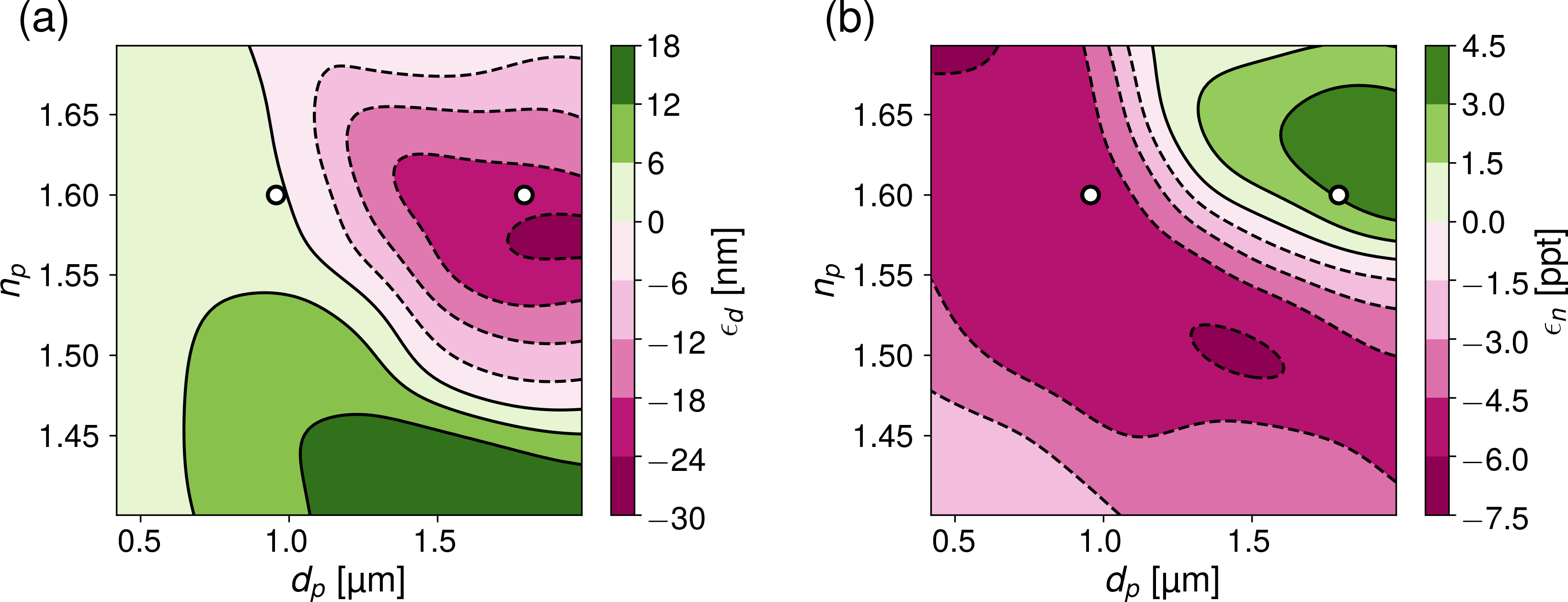
We validate the combination of DDA hologram synthesis and Lorenz-Mie analysis by performing numerical experiments on homogeneous spheres for which Eq. (2) should be exact. In this case, fitted values for the diameter, , and the refractive index, , should agree with the ground-truth values, and , used as inputs. Figure 2(a) presents a map of the errors in the estimated diameter, , as a function of the ground-truth inputs. Figure 2(b) shows corresponding results for errors in the refractive index, . The DDA and Lorenz-Mie formulations agree on the spheres’ diameters to within the precision of holographic characterization measurements over more than half of the selected parameter range, the agreement being better than for smaller spheres. Errors in refractive index generally are smaller than across the entire domain, which also is reasonable for our application. Errors in both diameter and refractive index are consistent with previous reports of the performance of the DDA yurkin_discrete_2007 ; yurkin_discrete-dipole-approximation_2011 .
The discrete data points in Fig. 2(a) and Fig. 2(b) represent the properties of the micrometer-diameter polystyrene spheres that were used for reported molecular binding assays cheong_flow_2009 ; zagzag_holographic_2020 . The computational methods’ errors in size and refractive index are comparable to instrumental uncertainties for the smaller of these particles, but exceed instrumental uncertainties for the larger. We focus our numerical study, therefore, on the characteristics of the smaller commercial probe beads, both for their immediate practical application to medical testing and also to assess the effective-sphere model under conditions where our techniques are most reliable.
II.2 Single Coatings
We next examine the effect of adding a single coating of a homogeneous material onto a uniform substrate sphere. This is a model for hologram formation by the probe beads used for holographic molecular binding assays. To facilitate comparison with recent experimental studies cheong_flow_2009 ; zagzag_holographic_2020 , we focus on the particular case of micrometer-diameter polystyrene spheres with and . The coating thickness, , and refractive index, , are selected at random from the range and . For each set of parameters, we use DDA to compute the coated sphere’s hologram and then fit to the effective-sphere model for and .
In the special case that the coating has the same refractive index as the substrate, , adding a coating is equivalent to increasing the diameter of the bead: . Alternatively, setting is equivalent to not adding a coating, which should yield .
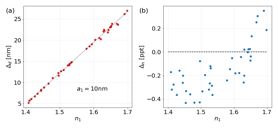
The results in Fig. 3 confirm that adding a molecular-scale coating increases the apparent diameter of the bead, , provided the coating’s refractive index is greater than that of the medium. As expected, the coating’s influence on the effective diameter depends on its refractive index relative to that of the substrate, with low-index coatings increasing by less than their thickness and high-index coatings increasing by more. Indeed, Fig. 4(a) shows that the apparent bead diameter increases nearly linearly with for a fixed layer thickness, . Extrapolating to yields , as expected. Similarly, setting yields . From this, we obtain a phenomenological relationship between the effective diameter and the properties of the coating:
| (3) |
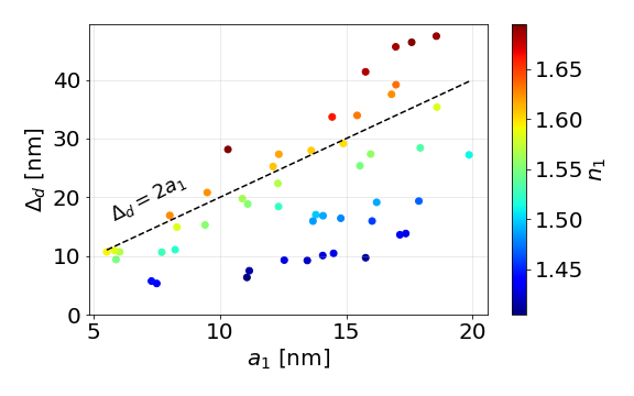
Figure 4(b) shows the corresponding influence of the coating’s refractive index, , on the effective sphere’s refractive index, . Unlike the diameter, the change in refractive index, , does not depend linearly on . Generally speaking, a low-index coating with reduces the effective refractive index, , while a high-index coating increases it. The overall magnitude of this effect is less than one part per thousand for the conditions considered, which suggests that trends in the effective refractive index are not likely to provide a practical basis for detecting and characterizing individual molecular overlayers.
II.3 Fractional coverage and partial coatings
Binding sites may not cover the surface of a probe bead uniformly, nor need target molecules fill all of the available binding sites. Such incomplete coverage is depicted schematically in Fig. 1(a). If target molecules with refractive index fill a fraction, , of the available sites, the remainder of the surface layer is filled with the fluid medium at refractive index . The surface layer then has an effective refractive index, , intermediate between and that is accounted for by Maxwell Garnett effective-medium theory markel_introduction_2016 :
| (4a) | |||
| where | |||
| (4b) | |||
is the Lorentz-Lorenz function. From this, we obtain an expression for the effective refractive index of the partial coating
| (5) | ||||
| (6) |
The assumed linear dependence of on the refractive index of the coating therefore suggests that the effective diameter of a probe bead depends on the filling factor, , as
| (7) | ||||
| (8) |
We predict, therefore, that the measured increase in the effective diameter is roughly proportional to the fractional coverage of bound molecules.
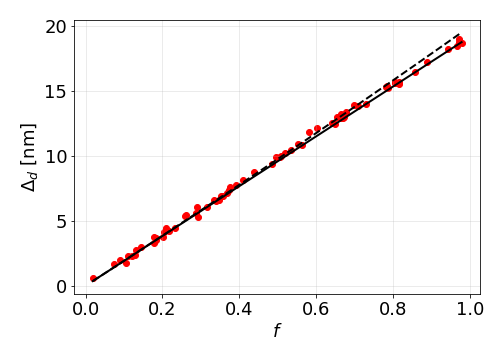
Figure 5 presents the representative case of , with a coating thickness of . This should be a reasonable model for a polystyrene sphere coated with a monolayer of protein. Discrete (red) data points represent results of numerical experiments for randomly selected filling fractions, ranging from a bare sphere at to a complete coating at . The solid line is a comparison with the linear approximation from Eq. (8), which interestingly agrees better with the data than the dashed curve representing the full expression from Eq. (7).
II.4 Molecular binding assays: Double coatings
The foregoing results show that the effective-sphere model reasonably models the light-scattering properties of the probe beads used for holographic molecular binding assays. We next address how those properties change when target molecules occupy the binding sites on the surface of a probe bead to form a second layer, as depicted in Fig. 1(a). We continue to choose and to model the micrometer-diameter polystyrene substrate bead used in experimental studies. Once the coating of binding sites is added, the probe beads have effective diameter and effective refractive index , both of which are determined by fitting to the effective-sphere model. Adding a layer of target molecules on top of this constitutes a model for a binding assay with effective properties and . The standard assay involves monitoring the difference, , in the probe beads’ effective diameter upon binding. We also monitor the change in refractive index, .
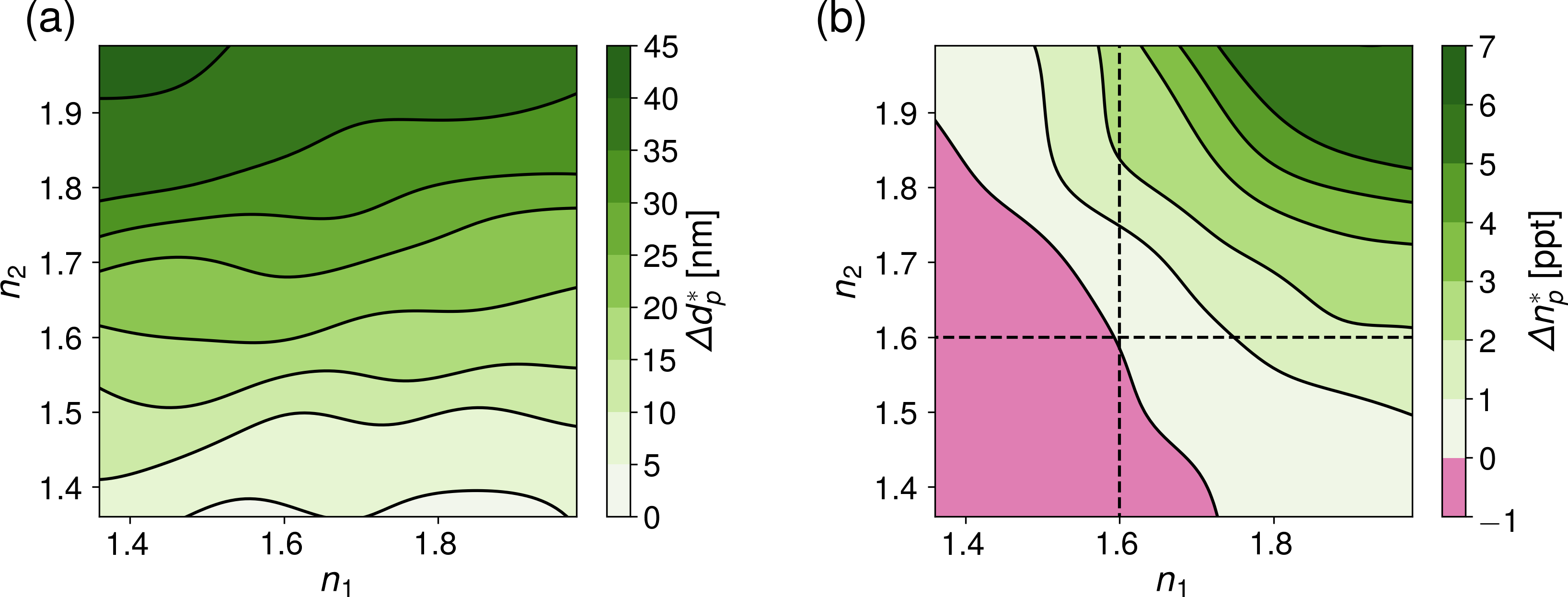
For concreteness, we choose the two coatings to have the same thickness, , while and are chosen at random between and . This range of refractive indexes matches expectations for protein coatings mcmeekin_refractive_1964 given that the the coatings may not be complete. Performing two fits to the effective-sphere model for each parameter pair yields measurements of and that are presented in Fig. 6(a) and Fig. 6(b), respectively.
Binding-induced increases in the effective diameter, , are found to be largely independent of the inner coating’s refractive index, . Changes in the apparent size depend much more strongly on the refractive index of the outer coating, . This is fortunate for practical molecular binding assays because it means that variations in the density of binding sites from bead to bead will not contribute disproportionately to variations in and therefore in estimates for the filling fraction, . This, in turn, increases the reliability of measurements of the concentration of target molecules based on holographic measurements of .
Binding-induced changes in the bead’s refractive index are far more subtle than changes in the size. The influence of the outer coating on both the apparent size and refractive index increases as the refractive index of the coating becomes more mismatched with the refractive index of the substrate bead. These observations suggests that the sensitivity of molecular binding assays can be improved by reducing the refractive index of the substrate beads. Previous experiments have used commercial polystyrene substrate beads with relatively high refractive indexes, . Better choices might include silica with a refractive index around , poly(methyl methacrylate) (PMMA) with a refractive index around , and 3-(trimethoxysilyl)propyl methacrylate (TPM) with a refractive index around van_der_wel_preparation_2017 ; middleton_optimizing_2019 .
III Comparison with Experiments
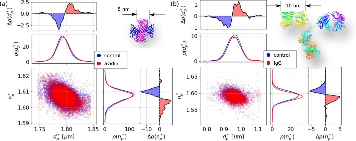
Insights gained from these numerical studies are useful for interpreting experimental realizations of holographic molecular binding assays cheong_flow_2009 ; zagzag_holographic_2020 . The data in Fig. 7 are reproduced from Ref. zagzag_holographic_2020 and show how molecular binding changes effective-sphere properties in two cases: avidin binding to biotinylated polystyrene spheres (Fig. 7(a)) and IgG binding to polystyrene spheres coated with protein A (Fig. 7(b)). Each point in the scatter plot represents the measured diameter and refractive index of a single colloidal particle dispersed in a buffer containing dissolved target molecules. The dark (blue) data points represent the properties of the probe beads, and , before incubation. The light (red) points represent properties of the same population of beads after incubation, and . To facilitate comparisons, we also plot projected probability distributions, and , of the measured diameters and refractive indexes, respectively, both before and after incubation. The differences in these distributions, and , emphasize shifts in the distributions due to incubation with target molecules.
The biotinylated probe spheres have a mean diameter of . This increases to after tetrameric avidin binds to the beads. Confidence intervals for these values represent the uncertainty in the mean of more than particles in each data set and therefore are much smaller than the uncertainty in a single-bead measurement. The observed shift of is smaller than the domain size of avidin. Whereas the beads’ diameter increases upon binding, their measured refractive indexes decrease from to , a net change of . The probe beads’ refractive index is consistent with expectations for polystyrene, presumably because biotin is a small molecule; a coating of biotin therefore does not substantially affect the substrate beads’ light-scattering properties.
The protein A-coated spheres have a mean diameter of before incubation with the antibody IgG. This increases to after incubation resulting in a shift of . This increase is larger than was observed for the avidin-biotin system presumably because IgG is substantially larger than tetrameric avidin. Once again, however, is much smaller than the size of the target molecule. Uncertainties are larger in this case because the statistical ensemble consists of only per sample.
As for the biotin-avidin system, binding IgG causes the probe beads’ refractive index to shift downward from before binding to after, a decrease of . The initial refractive index of the protein A coated probe beads is smaller than expectations for polystyrene presumably because of the influence of the protein. Protein A is nearly as large as tetrameric avidin and might be expected to have a comparably sizable influence.
In both cases, binding with target molecules leads to an increase in the holographically measured particle diameter that is smaller than the physical size of the target molecules and a decrease in the measured refractive index. Looking to the results in Fig. 6, these trends can be explained if the coatings of bound molecules have lower refractive indexes than the effective refractive index of the substrate beads. Specifically, we interpret these results to show that both avidin and IgG have refractive indexes substantially smaller than at the densities of the experimentally obtained coatings. Choosing substrate beads with lower refractive indexes therefore should increase the apparent shift in bead diameter upon binding thereby increasing the target molecules’ influence on holographically measurable properties and improving the sensitivity of the assay.
IV Conclusions
We have used the discrete-dipole approximation to model label-free bead-based molecular binding assays performed with holographic particle characterization in the effective-sphere approximation. Our computational study confirms that interpreting the holograms of coated sphere with the Lorenz-Mie theory for homogeneous spheres yields valuable information on the presence and characteristics of the coatings while retaining the demonstrated speed and robustness of standard holographic particle characterization. Our study validates previous experimental reports of holographic molecular binding assays cheong_flow_2009 ; zagzag_holographic_2020 and explains trends in those measurements as arising from the mismatch in refractive index between the substrate beads and the molecular coatings. Because this mismatch depends on the filling factor, , of bound molecules on the beads’ surfaces, the particles’ effective diameters and refractive indexes change continuously as binding proceeds. We have shown that changes in the diameter scale linearly with to a very good approximation. This means that trends in the holographically measured diameter can be mapped directly onto trends in the fraction of filled binding sites.
Our results furthermore provide guidance for optimizing holographic molecular binding assays. Most notably, the sensitivity of such assays to variations in the filling factor, , of the available binding sites can be increased by reducing the refractive index of the substrate beads. The polystyrene substrates used for many standard bead-based assays are not the best choice for this application, therefore, because their refractive index is quite high. Alternatives such as silica, PMMA and TPM spheres offer attractive alternatives for such assays. Fluorinated latex spheres might be an exceptionally good choice sacanna_microemulsion_2004 . The choice of substrate for holographic molecular binding assays therefore can be optimized both for optical properties and also for physical properties such as buoyancy to facilitate processing of tests. Beads of different sizes and compositions can be functionalized with different binding sites and combined into a multiplexed assay. The individual tests can be monitored in parallel through the unique ability of holographic particle characterization to differentiate particles by both size and refractive index. These considerations should be particularly useful for designing serological and diagnostic tests for viral infection, with immediate urgency begin placed on addressing the ongoing COVID-19 pandemic.
The open-source software used for this study is available at https://github.com/laltman2/DDA_binding_assays.
Funding
National Science Foundation (NSF) (1420073, 2027013).
Acknowledgments
This work was supported primarily by the MRSEC program of the National Science Foundation through Award No. DMR-1420073. Additional funding was provided by the RAPID program of the National Science Foundation through Award No. DMR-2027013.
Disclosures
DGG: Spheryx, Inc. (F,I,P,S).
References
- (1) J. Sheng, E. Malkiel and J. Katz. “Digital holographic microscope for measuring three-dimensional particle distributions and motions.” Applied Optics 45, 3893–3901 (2006).
- (2) S.-H. Lee, Y. Roichman, G.-R. Yi, S.-H. Kim, S.-M. Yang, A. van Blaaderen, P. van Oostrum and D. G. Grier. “Characterizing and tracking single colloidal particles with video holographic microscopy.” Optics Express 15, 18275–18282 (2007).
- (3) C. F. Bohren and D. R. Huffman. Absorption and scattering of light by small particles (Wiley, 1983).
- (4) M. I. Mishchenko, L. D. Travis and A. A. Lacis. Scattering, Absorption, and Emission of Light by Small Particles (Cambridge University Press, 2002).
- (5) G. Gouesbet and G. Gréhan. Generalized Lorenz-Mie theories, vol. 31 (Springer, 2011).
- (6) B. J. Krishnatreya, A. Colen-Landy, P. Hasebe, B. A. Bell, J. R. Jones, A. Sunda-Meya and D. G. Grier. “Measuring Boltzmann’s constant through holographic video microscopy of a single sphere.” American Journal of Physics 82, 23–31 (2014).
- (7) F. C. Cheong, B. Sun, R. Dreyfus, J. Amato-Grill, K. Xiao, L. Dixon and D. G. Grier. “Flow visualization and flow cytometry with holographic video microscopy.” Optics Express 17, 13071–13079 (2009).
- (8) Y. Zagzag, M. F. Soddu, A. D. Hollingsworth and D. G. Grier. “Holographic molecular binding assays.” Scientific Reports 10, 1–7 (2020).
- (9) M. Hannel, C. Middleton and D. G. Grier. “Holographic characterization of imperfect colloidal spheres.” Applied Physics Letters 107, 141905 (2015).
- (10) C. Wang, F. C. Cheong, D. B. Ruffner, X. Zhong, M. D. Ward and D. G. Grier. “Holographic characterization of colloidal fractal aggregates.” Soft matter 12, 8774–8780 (2016).
- (11) C. Wang, X. Zhong, D. B. Ruffner, A. Stutt, L. A. Philips, M. D. Ward and D. G. Grier. “Holographic characterization of protein aggregates.” Journal of pharmaceutical sciences 105, 1074–1085 (2016).
- (12) J. Fung and S. Hoang. “Computational assessment of an effective-sphere model for characterizing colloidal fractal aggregates with holographic microscopy.” Journal of Quantitative Spectroscopy and Radiative Transfer 236, 106591 (2019).
- (13) M. A. Odete, F. C. Cheong, A. Winters, J. J. Elliott, L. A. Philips and D. G. Grier. “The role of the medium in the effective-sphere interpretation of holographic particle characterization data.” Soft Matter 16, 891–898 (2020).
- (14) V. A. Markel. “Introduction to the Maxwell Garnett approximation: tutorial.” JOSA A 33, 1244–1256 (2016).
- (15) F. C. Cheong, K. Xiao, D. J. Pine and D. G. Grier. “Holographic characterization of individual colloidal spheres’ porosities.” Soft Matter 7, 6816–6819 (2011).
- (16) F. C. Cheong, P. Kasimbeg, D. B. Ruffner, E. H. Hlaing, J. M. Blusewicz, L. A. Philips and D. G. Grier. “Holographic characterization of colloidal particles in turbid media.” Applied Physics Letters 111, 153702 (2017).
- (17) B. T. Draine and P. J. Flatau. “Discrete-Dipole Approximation For Scattering Calculations.” JOSA A 11, 1491–1499 (1994).
- (18) W. J. Wiscombe. “Improved Mie scattering algorithms.” Applied Optics 19, 1505–1509 (1980).
- (19) W. Yang. “Improved recursive algorithm for light scattering by a multilayered sphere.” Applied Optics 42, 1710–1720 (2003).
- (20) O. Peña and U. Pal. “Scattering of electromagnetic radiation by a multilayered sphere.” Computer Physics Communications 180, 2348–2354 (2009).
- (21) B. J. Krishnatreya and D. G. Grier. “Fast feature identification for holographic tracking: the orientation alignment transform.” Optics Express 22, 12773–12778 (2014).
- (22) L. E. Altman and D. G. Grier. “CATCH: Characterizing and Tracking Colloids Holographically Using Deep Neural Networks.” The Journal of Physical Chemistry B 124, 1602–1610 (2020).
- (23) S.-H. Lee and D. G. Grier. “Holographic microscopy of holographically trapped three-dimensional structures.” Optics Express 15, 1505–1512 (2007).
- (24) H. Shpaisman, B. Jyoti Krishnatreya and D. G. Grier. “Holographic microrefractometer.” Applied Physics Letters 101, 091102 (2012).
- (25) A. Yevick, M. Hannel and D. G. Grier. “Machine-learning approach to holographic particle characterization.” Optics Express 22, 26884 (2014).
- (26) M. A. Yurkin and A. G. Hoekstra. “The discrete dipole approximation: An overview and recent developments.” Journal of Quantitative Spectroscopy and Radiative Transfer 106, 558–589 (2007).
- (27) M. A. Yurkin and A. G. Hoekstra. “The discrete-dipole-approximation code ADDA: Capabilities and known limitations.” Journal of Quantitative Spectroscopy and Radiative Transfer 112, 2234–2247 (2011).
- (28) S. Barkley, T. Dimiduk, J. Fung, D. Kaz, V. N. Manoharan, R. McGorty, R. Perry and A. Wang. “Holographic Microscopy with Python and HoloPy.” Computing in Science Engineering 1–1 (2019).
- (29) T. L. McMEEKIN, M. L. GROVES and N. J. HIPP. “Refractive Indices of Amino Acids, Proteins, and Related Substances.” In “Amino Acids and Serum Proteins,” vol. 44 of Advances in Chemistry, 54–66 (AMERICAN CHEMICAL SOCIETY, 1964).
- (30) C. van der Wel, R. K. Bhan, R. W. Verweij, H. C. Frijters, Z. Gong, A. D. Hollingsworth, S. Sacanna and D. J. Kraft. “Preparation of Colloidal Organosilica Spheres through Spontaneous Emulsification.” Langmuir 33, 8174–8180 (2017).
- (31) C. Middleton, M. D. Hannel, A. D. Hollingsworth, D. J. Pine and D. G. Grier. “Optimizing the Synthesis of Monodisperse Colloidal Spheres Using Holographic Particle Characterization.” Langmuir 35, 6602–6609 (2019).
- (32) S. Sacanna, G. H. Koenderink and A. P. Philipse. “Microemulsion Synthesis of Fluorinated Latex Spheres.” Langmuir 20, 8398–8400 (2004).