SkyHaul: An Autonomous Gigabit Network Fabric In The Sky
Ramanujan K Sheshadri, Eugene Chai, Karthikeyan Sundaresan, Sampath Rangarajan
NEC Laboratories America, Inc.
(ram,eugene,karthiks,sampath)@nec-labs.com
Abstract
We design and build SkyHaul, the first large-scale, autonomous, self-organizing network of unmanned aerial vehicles (UAVs) that are connected using a mmWave wireless mesh backhaul. While the use of a mmWave backhaul paves the way for a new class of bandwidth-intensive, latency-sensitive cooperative applications (e.g. LTE coverage during disasters, surveillance during rescue in challenging terrains), the network of UAVs allows these applications to be executed at operating ranges that are far beyond the line-of-sight distances that limit individual UAVs today.
To realize the challenging vision of deploying and maintaining an airborne, mmWave mesh backhaul to cater to dynamic applications/events,
SkyHaul’s design incorporates various elements: (i) Role-specific UAV operations that simultaneously address application tracking and
backhaul connectivity (ii) Novel algorithms to jointly address the problem of deployment (position, yaw of UAVs) and traffic routing across the UAV network;
and (iii)A provably optimal solution for fast and safe reconfiguration of UAV backhaul during application dynamics.
We implement SkyHaul on four DJI Matrice 600 Pros to demonstrate its practicality and performance
through autonomous flight operations, complemented by large scale simulations.
1 Introduction
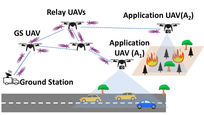
We envision a self-organizing network of unmanned aerial vehicles (UAVs), interconnected through a mmWave mesh backhaul (Fig. 1) to enable a new class of cooperative, gigabit [1] airborne applications. Gigabit applications [2] are poised to transform every aspect of our communities. With mmWave UAV meshes, we bring the benefits of ubiquitous Gigabit wireless to a whole new class of applications such as wide-area high-definition (4K) video streaming; multi-Gbps 5G coverage for users and first responders in public-safety situations [3, 4] even under challenging conditions; on-demand, city-wide IoT connectivity; and immersive AR/VR streaming from any location [5]. We refer to these applications as Gigabit Applications in the Sky, and our enabling technology as a Gigabit Network Fabric in the Sky.
Industry operators have been exploring practical multi-UAV capabilities, from the “UAV tower” proposal by Amazon [6] to the use of high altitude balloons for internet service by Google [7]. However, these early attempts do not fully realize the potential of an airborne Gigabit network fabric. We argue that the key enabler behind our vision is the capability for multiple UAVs to exchange/route data and coordinate over a high-bandwidth backhaul to increase solution coverage to the necessary, practical scale. In this paper, we address the design and algorithmic challenges behind such a technology enabler for on-demand deployments, and answer the following question in the process: How do we design and deploy an open and flexible network of UAVs equipped with a high-bandwidth backhaul for real-time coverage of dynamic events over a wide area?
Key Benefits of a multi-UAV Gigabit Fabric. A multi-UAV, airborne mmWave Gigabit mesh brings with it several key features for a new generation of applications:
Extended Operating Range: Existing UAV operations are largely confined to line-of-sight operations that are bounded by the range of the RF link between the ground station and the UAV. With a UAV network, the operating range of all UAVs is extended through the network of UAVs that form a multi-hop mesh network for communications and control. Such a network can be deployed, on-demand to provide LTE coverage in public safety situations [3] (e.g. areas hit by hurricanes), or as a wide-area search-and-rescue or surveilliance assistance in inaccessible areas.
High Bandwidth Applications: Beyond this increased coverage, a Gigabit airborne fabric enables high bandwidth applications that are previously impossible. E.g., Consider UAVs live broadcasting Daytona 500 [8]. Existing approaches are either limited to lower quality video streams (1080 or 720p), or require a tethered UAV for high-resolution streams. With a mmWave (60GHz) mesh backhaul operating at 1Gbps, we can have a full-resolution 8K 24FPS live stream using a RED MONSTRO camera [9] on an untethered UAV.
UAV-Attached Cloud Computing: Onboard compute capability available to current UAVs is highly constrained due to size and power limitations. With a high-bandwidth, low latency mmWave mesh, cloud-based compute resources on the ground can be seamlessly integrated. Real-time, closed loop UAV network control using data streamed from UAVs and cloud-based AI/analytics inference applications can now be built over such a Gigabit UAV network fabric. As an illustration, we enabled real-time object recognition using a 4K video stream over our 60GHz UAV network. With only a 2 delay between video capture at the UAV we achieved highly accurate object identification at our cloud servers with 97% of supported objects in the video being detected.
Challenges. Although there are many benefits of a mmWave mesh on UAVs, realizing it in practice is challenging requiring us to address multiple systems and algorithmic hurdles.
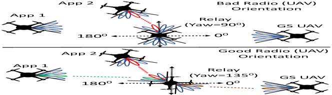
High Capacity vs Fragile Connectivity: 60GHz links are fragile and constant UAV mobility, coupled with multiple hops, exacerbates the connectivity challenge. Unlike traditional WiFi radios which use omni-directional antennas, the 60GHz radios use phased-array antennas, each with a limited field-of-view (FOV) a.k.a. sector of operation. As we highlight later in §2, the achievable throughput is unequal across this entire sector, with the highest throughput available at beam angles and decreasing as the beams are steered towards the edge of the FOV. Consequently, even with multiple radios covering , the orientation of the radio with respect to its sender/receiver (as determined by the UAV’s yaw – UAV orientation along the vertical axis) has a significant impact on end-to-end performance, particularly during radio capacity sharing in mesh deployments (e.g. Fig. 2). Such an impact (UAV’s yaw) on 60 GHz link performance is unique to UAVs, and is complementary to the well-studied 802.11ad link-layer mechanisms (beam and rate selection) within a single radio at a fixed orientation.
Managing the Backhaul Network: In order to optimally manage the backhaul network, one needs to jointly solve for the optimal (a) topology of the UAVs, and (b) traffic route between the UAVs and the ground station. The topology, defined by the number of UAVs deployed along with the position and yaw of each UAV is tightly coupled with the routing policy employed throughout the backhaul network: Position and yaw of each UAV determines its connectivity and capacity to its neighboring UAVs, which in turn affects how this capacity is shared by multiple end-to-end traffic flows from other UAVs. Hence, solving for either topology or routing in isolation results in a suboptimal UAV deployment solution. Adding to the problem’s complexity is the need to find a solution using the smallest number of UAVs, so as to best use the available UAV resources to serve the application. This challenge, and even subsets of them (e.g. solving for topology discounting the routing policy) is NP-Hard. In contrast to prior mesh networking solutions [10, 11, 12], this three-dimensional problem (position, orientation and routing) is unique to reconfigurable mmWave UAV networks, thereby requiring a novel approach. To the best of our knowledge, we are the first to address it comprehensively.
Tracking Event Dynamics: With UAV networks, there is a fundamental tradeoff between the coverage needs of the application or mission, and the requirements of the UAVs to maintain mesh connectivity. Mobility requirements to meet application goals (e.g. tracking a fast moving vehicle or event) may result in network disconnection, preventing the mesh from providing always-on, high-bandwidth connectivity between UAVs and the ground station. Conversely, maintaining a static configuration to ensure high bandwidth routes can limit the UAV network from providing the necessary coverage demanded by applications. Further, severe limitations on power and weight requirements of UAV payloads, requires us to carefully balance the use of multiple mmWave radios (for increased connectivity/capacity) with that of multiple sensors such as lidars, cameras, etc.(for better application coverage).
Safe Re-configuration of the Backhaul: When catering to event dynamics, the UAVs need to migrate (move) to a new configuration to continue their coverage and satisfy application demands. However, this must be conducted quickly, yet in a collision-free manner – a challenge that is central to the self-configuring capability of the UAV backhaul network.
SkyHaul. In this paper, we design and deploy SkyHaul, the first large-scale, airborne, self-organizing, multi-UAV network that operates over a 60GHz mesh backhaul. With each UAV carrying multiple 60GHz interfaces, the 60 GHz mesh network forms a data plane that carries high bandwidth data between all UAVs, and a ground station bridge that is connected to external resources. A separate control plane (over 60GHz or public LTE) provides command and control of all SkyHaul UAVs in the network.
To simultaneously cater to the
objectives of application coverage and backhaul connectivity, SkyHaul employs
functionally-specialized UAV operation as shown in Fig. 1:
Application UAVs focus their mobility decisions to meet
application-specific objectives such as target tracking, cellular
coverage [3], etc.111Optimizing application UAVs’ objective is out-of-scope of this work., while Relay UAVs focus theirs on forming and
maintaining a robust backhaul network to connect the Application UAVs to the
ground station even during event dynamics – the latter forming the focus of SkyHaul. This also has the added benefit of
role-optimized payload design: Application UAVs carry a payload with more
sensors (e.g. cameras, Lidar, etc.) and fewer radios, while Relay UAVs
carry more radios and fewer sensors. Note however that UAVs can be
repurposed for either roles as warranted by the SkyHaul’s design. Finally, a
Ground Station UAV hovers above or close to the station on the ground,
and serves as an airborne last-hop link connecting SkyHaul’s network to the
outside world.
SkyHaul’s key contributions are:
Characterizing 60GHz Links on UAVs. To understand the impact of UAV’s yaw (along with distance) on its link performance and consequently SkyHaul’s deployment decisions, we conduct extensive measurements of UAV-mounted 60GHz links over varying distances and yaw angles. A comprehensive, yet practical model of 60GHz link throughput on UAV platforms as a function of its yaw and distance is determined, to complement the traditional 802.11ad link layer adaptations.
Novel algorithm for efficient positioning, orientation and traffic routing across UAVs. Through a novel two-step optimization across radial and angular deployment directions, SkyHaul jointly solves the problem of UAVs network configuration across three dimensions: (i) the appropriate quantity and position of UAVs to be deployed; (ii) the yaw of the UAVs such that the position of the onboard 60GHz interfaces establish a desired mesh connectivity topology between the deployed UAVs as well as the ground station (GS); and (iii) the routing of traffic between UAVs and the GS to satisfy the application’s traffic demands.
Provably optimal algorithm for fast backhaul re-configuration. SkyHaul employs a provably safe algorithm that leverages multiple layers of altitude to ensure that reconfiguration of the UAVs’ position and yaw is carried out quickly (in shortest time) in response to dynamic events, while remaining collision-free.
Real-world implementation of SkyHaul. We implement SkyHaul on a UAV network of four DJI M600Pro platforms, and evaluate its performance under real-world conditions. Application UAVs carry one Mikrotik 60GHz interface [13] and a 4K camera, while Relay and Ground Station UAVs each carry upto three 60GHz interfaces. Routing and managing the UAVs and their 60GHz radios are done via an on-board Intel Core i7 platform. The SkyHaul controller runs on AWS [14], and is connected to all UAVs via a LTE interface on each UAV.
Through several real-world event tracking experiments, we first demonstrate SkyHaul’s ability to efficiently deploy, maintain and adapt its mmWave backhaul network in real-time to support both dynamic communication (data transfer) and sensing (live video streaming and analytics) applications. Next, using SkyHaul’s emperical throughput model, we conduct large-scale simulations to show that SkyHaul’s algorithms can support twice the traffic demands for a given number of UAVs, or satisfy the desired traffic demands using half the number of UAVs, over baseline solutions addressing either of the respective objectives. A video of SkyHaul demonstration can be found at [15].
2 Characterizing 60GHz UAV Links
Outdoor 60Ghz radios require LOS and appropriate relative orientation between radios to establish a connection. Therefore, it becomes critical to understand and model the impact of UAV’s yaw (orientation) on link performance at coarse time scales (secs), which is essential for SkyHaul’s deployment decisions. Note that this is different from and complementary to traditional mmWave link models [16, 17, 18] that capture link performance (e.g., beam selection) on fine time-scales (millisecs), but for a given radio orientation.
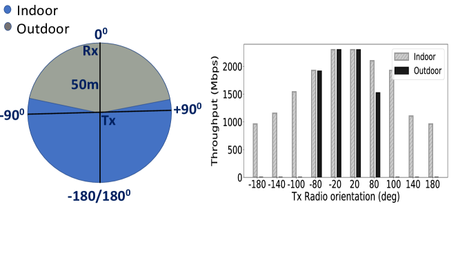
Indoor vs. Outdoor Angular Coverage. To highlight the impact of multipath-free outdoor operating environment, we compare the performance of our 60GHz platform in outdoor airborne scenarios, against that in a large indoor hall. Fig. 3 shows the azimuth angular coverage and throughput, when Tx and Rx radios are placed 50m apart LOS, in both indoors and outdoors. We change the relative angles between the Tx and Rx radios by rotating the Tx radio about its fixed position. We see that when the radios are indoors, rich multipath allows coverage to be maintained as long as the Tx radio is pointed of the Rx radio. However, when the UAVs are moved outdoors, angular coverage is limited to — a significant drop from that in the indoor measurement.
| Mcs | RSS | Bitrate |
| Index | (dBm) | (Mbps) |
| 8 | -61 | 2310 |
| 7 | -62 | 1925 |
| 6 | -63 | 1540 |
| 4 | -64 | 1155 |
| 3 | -65 | 962.5 |
| 2 | -66 | 770 |
| 1 | -68 | 385 |
| 0 | -78 | 27.5 |
2.1 60GHz Link Measurement Study
We now briefly discuss the details of our measurement study of the 60GHz radios mounted on UAVs. Further details of our 60GHz operating setup can be found in §4.1.
60GHz Radios. We mount MikroTik WAP 60G [13] long-range 60GHz radios on DJI M600Pro UAVs for our experiments. These 802.11ad devices utilize a Qualcomm QCA6335 chipset and a 32 phased array antenna, and support three non-overlapping channels. Proprietary beam and rate selection algorithms based on the RSS are used to select optimal operating parameters for each 60GHz link. A single link supports PHY bitrate of up to 2.3Gbps (Modulation index 0 to 8). In our experiments, we fix the transmission power to maximum, to achieve maximum link coverage.
Data Collection. We characterize the 60 GHz link performance using UDP traffic. We fly two UAVs (a Tx and a Rx UAV) at 60m altitude (has a clear LoS), and increase the separation distance between them from 40 to 400m, in steps of 40m. At each distance, we rotate the Rx and Tx UAVs in turn from to ( being the perfect alignment of Tx/Rx antennas), while keeping the other UAV at . We send UDP traffic using iperf3 and log the throughput every second. We also log the PHY bitrate, beam angle, RSS, and UAV telemetry data (position and yaw).
Link throughput is determined by two main factors – distance and angular difference between the radios. To analyze the effect of each, we decouple them and study their impact individually.
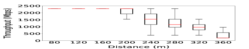
Throughput vs. Distance. We fix the angular difference between two UAVs’ radios to (i.e. both the Tx and Rx radios are directly facing each other) and measure the impact of distance on the throughput. Fig. 5 shows the change in the received throughput for different distances between the two UAVs. The high variance in the instantaneous throughput is due to the UAV’s volatility (e.g. vibrations, jerks) in the air, to which, 802.11ad’s highly sensitive rate selection mechanism adapts. Even a small change of 1dB in RSS results in radios selecting a different PHY rate as shown in Fig. 5. Nevertheless, we still observe a clear monotonic, declining trend in the median link throughput as the distance increases.
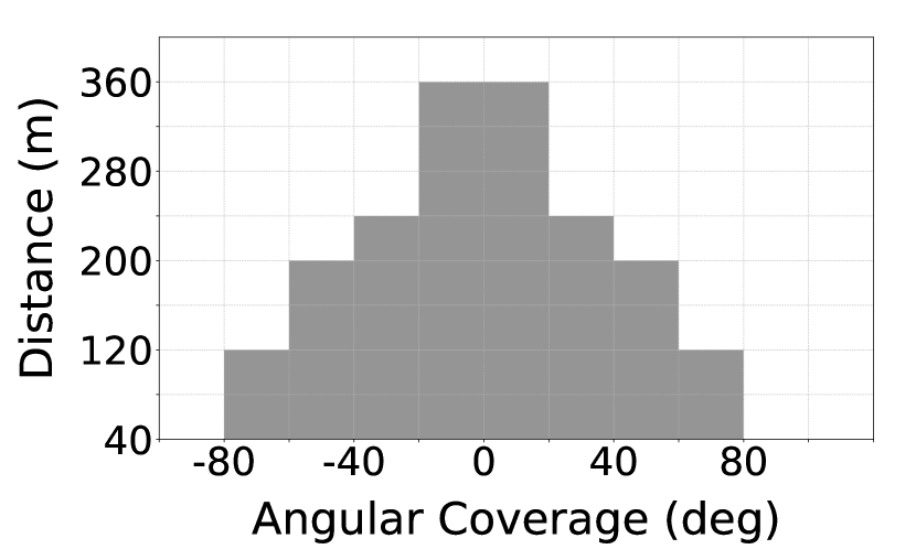
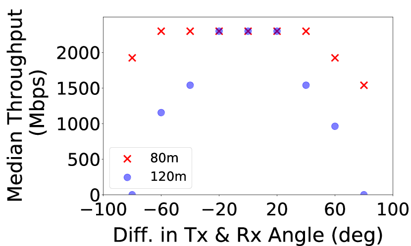
Throughput vs. Relative Yaw. For a given yaw angle () of the Rx UAV, we vary the relative yaw angle of the Tx UAV from to , while sampling throughput measurements at regular yaw intervals. Fig. 6(a) shows a binary map denoting successful 60GHz link connectivity (i.e. when throughput > 100Mbps) at different distances and relative yaws. Although the radio’s (MikroTik) specifications prescribes an antenna coverage of only (to ), we observe that connectivity can be established across relative yaws from to when the UAVs are apart, while only between and for distances greater than . This is because the side-lobes of the Tx beam have sufficient energy to establish connectivity at short ranges, increasing the angular coverage. However, the side-lobes have no impact at longer ranges, where the main lobes determine coverage. This interplay between main and side-lobes is also reflected in the achieved throughput over the 60GHz channel: Fig. 6(b) shows that at short distances (), the maximum median throughput is achieved over a wider range of relative yaw angles than at longer UAV distances ().
2.2 60GHz UAV Link Throughput Model
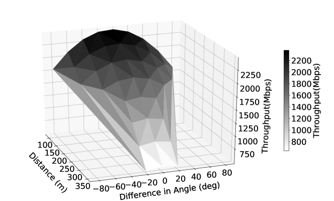
Based on our measurement study, we can now characterize the throughput model of our 60 GHz UAV links as a function of both the relative UAV distance () and yaw angles (). A weighted least-square regression approach that accounts for heteroscedasticity of the throughput numbers in our dataset, results in the following quadratic model as the best fit: , where are constants derived from the regression curve-fitting technique. Fig. 7 shows the surface curve-fitting of the model that accurately captures the parabolic dependence of throughput on both and .
Leveraging the model. While a throughput’s quadratic dependence on distance is expected in a LoS environment, the model’s contribution lies in its incorporation of the joint dependence on both relative distance and yaw. Indeed, while 802.11ad’s link adaptation mechanisms are meant to handle instantaneous (millisecs granularity) throughput fluctuations (due to UAV volatility), SkyHaul’s throughput model is meant to complementarily capture the impact of UAV’s yaw on first-order (median, mean) throughput statistics. The latter allows SkyHaul to optimize its deployment decisions that are executed at coarse time scales (mins granularity). Further, constructing this model is a one-time effort that depends only on the mmWave radios and antennas employed.
3 SkyHaul Design
3.1 SkyHaul Overview
SkyHaul envisions to provide real-time coverage and tracking of a target application (e.g. mobile connectivity, live video surveillance, etc.) from a Ground Station (GS) that could be far away, using one or more UAVs. To allow applications to flexibly and dynamically define their “Regions Of Interest" (ROIs) on the ground based on their individual requirements, SkyHaul decouples the objectives of application coverage and backhaul connectivity, while focusing on the latter. It realizes this through functionally-specialized UAV operation: Application UAVs are tasked with specific ROIs by the application and move freely within their AOI (“airspace of interest"; i.e., airspace above the ROI assigned) to optimally track the target application, while Relay UAVs focus only on forming, maintaining and adapting a robust backhaul network to connect the dynamic Application UAVs to the GS. This has the added benefit of role-optimized payload design: Application UAVs carry a payload with more sensors (e.g. cameras, Lidars, etc.) and few radios, while Relay UAVs carry more radios and less sensors. Note however, UAVs can be repurposed for either roles as required by the application.
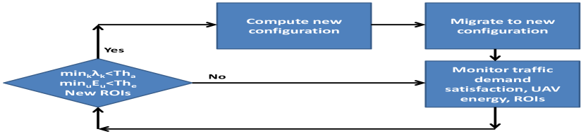
With the application UAVs being directed by the application, SkyHaul focuses on orchestrating the backhaul network of Relay UAVs to satisfy the application requirements. SkyHaul accomplishes this through a simple operating control loop, as shown in Fig. 8. When the SkyHaul network is first initialized or a configuration update is triggered, it (i) determines an efficient network configuration of Relay UAVs to meet the desired application objectives. Then, SkyHaul (ii) computes a seamless migration plan to enable UAVs (both Relay and Application) to optimally and safely deploy and reconfigure themselves in this configuration. Once the UAVs are in their new configuration, SkyHaul continuously (iii) monitors performance across the 60GHz mesh and triggers a reconfiguration step (along with migration, if necessary) if: (a) traffic satisfaction (of application sessions, ) falls below a desired threshold (), (b) UAVs need to be brought back (and replaced with another UAV) for energy (battery/gas) replenishment (when energy below ), or (c) when Application UAVs have been re-tasked to cover new ROIs.
3.2 Determining Efficient Configurations
3.2.1 Understanding the Problem
Formulation. SkyHaul’s objective is to cover and track an application/event that spans across multiple regions on the ground (ROIs, refer Fig. 1), from corresponding, non-overlapping zones above in the sky (AOIs, ) at a given altitude (i.e. a 2D deployment plane222The benefits of deploying UAVs at different altitudes (other than during transient mobility) are unclear, especially in light of connectivity requirements that are better addressed at the same altitude.). Thus, each of these zones generates a traffic demand (e.g. video streams) that needs to be delivered through one or more Relay UAVs to the ground station UAV (node , positioned above GS, last-hop connecting the Relay UAVs to the GS), which is assumed to be at the origin in the deployment plane. The static GS UAV that anchors the backhaul UAV-relay network, has one of its radios pointed down towards the GS (Z axis), unlike all other UAV radios (oriented in the XY-plane).
This problem of Relay-UAV network configuration (DCR) requires a joint optimization across three components: (i) Deployment (placement) of UAVs; (ii) Connectivity between UAVs and ground station (GS) as determined by orientation (yaw) of UAVs’ radios; and (iii) Routing of traffic between UAVs and GS to satisfy the application’s traffic demands. For easier exposition of the formulation and solution, a single ground station (GS) is considered. Furthermore, from a practical realization standpoint, we consider flow routing to be non-splittable, i.e. traffic in a session between Application UAVs and the GS must be routed without being split at any intermediate UAV, albeit, the latter can route flows of multiple sessions. The formulation and solution can be adapted to meet the setting of multiple ground station UAVs and splittable flow easily.
| DCR: | (1) | ||||
| s.t., | |||||
denotes the network configuration to be determined, , where each element in the configuration
corresponds to that of a UAV , namely its position , orientation
and its flow routing . Each
element of is a binary variable corresponding to whether flow is
routed from to (i.e. ).
is the expected throughput of the link , which (from §2), depends on the distance between them
(i.e their locations, ) and their respective radios’ orientation (), i.e.
.
The adjacent radios (total of ) at a UAV are separated by radians, with each radio responsible
for covering its logical sector of radians.
is a binary variable that captures the
presence of UAV in the -th sector of UAV and depends on their
respective positions and also UAV ’s orientation . Note
that a UAV’s position is captured in terms of its polar coordinates
() taken with respect to the GS UAV at origin.
Objective. In practical environments, there is a need to maintain additional drones to meet increasing application demands or to replace existing drones with depleting energy. Hence, DCR’s objective is to find the deployment configuration with the least number of Relay UAVs (cost) that can completely satisfy () the current traffic demands, while yielding a feasible flow routing that accounts for directional connectivity/capacity constraints. However, its flexible framework allows for selecting appropriate configurations that maximize demand satisfaction for a given deployment cost as well (by evaluating solutions for varying ). The first three constraints above correspond to flow origination (at UAVs covering application ), termination (at GS UAV ) and conservation (UAVs in between). Note that SkyHaul can handle bi-directional traffic as well, where upstream and downstream flows will be considered as separate sessions. The final three constraints are responsible for coupling flow routing to the notion of directional connectivity and capacity at each of the UAVs – specifically, for all the links (incoming and outgoing) that share the capacity of a radio (i.e., all the neighbors that fall in the sector of that radio ) at a UAV , there must be a feasible time-sharing () of those links (third last constraint), taking into account their respective capacities, that is capable of carrying the desired fraction () of traffic demands (last two constraints). Energy. Note that energy consumption in drones is dominated by their mechanical operation rather than connectivity and hence not incorporated in DCR333Gas powered drones can operate for a few hours [21]. Nevertheless, SkyHaul will have the mechanisms needed to cope with the impact of energy-related network dynamics (Fig. 8).
Challenges. Addressing DCR encounters challenges at multiple levels. (i) Hardness of computing configurations: The 3-way optimization in DCR is unique to the UAV environment and has not been addressed before. Its extremely challenging nature is evident from the NP-hardness of solving even just one component (deployment using Euclidian Steiner trees [22], without considering orientation and routing) or two components (routing and orientation assuming deployment is given) jointly. (ii) Practical realization and adaptation of configurations: The Relay UAVs have to periodically adapt and reposition themselves in a new network configuration to seamlessly track a spatially evolving event (e.g., forest fire) and hence the Application UAVs. Such a migration of network configurations involving multiple UAVs simultaneously needs to be executed both quickly and safely (i.e., avoiding any UAV collisions).
Given the hardness of the simplest variants of the DCR problem, SkyHaul aims to design a solution that organically integrates the components of deployment, connectivity and routing to compute efficient configurations, along with the dynamic mechanisms needed to adapt and realize these configurations safely in practice.
3.2.2 An Efficient Dual-Step Algorithm
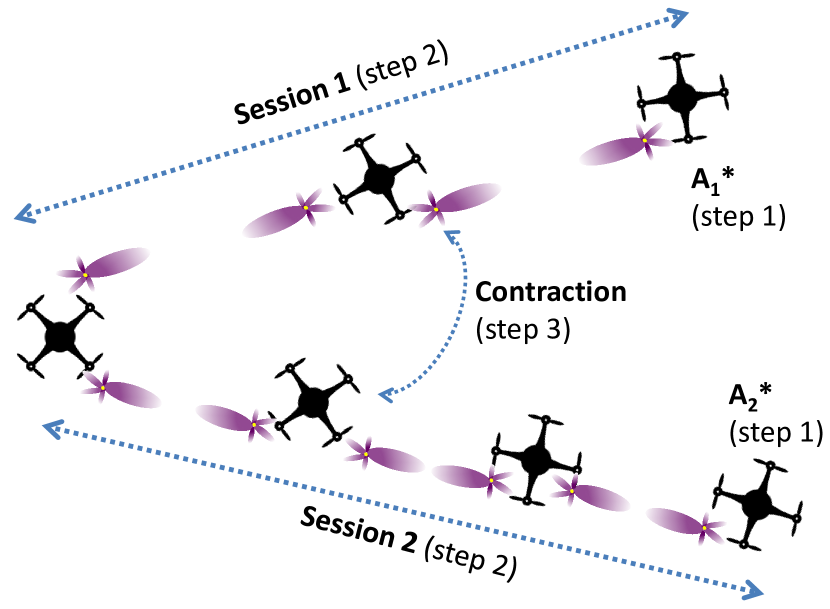
Given the position of the application UAVs, i.e. , SkyHaul determines an efficient UAV (backhaul) network configuration to satisfy their traffic demands through a novel two-step optimization (steps 2,3 in Fig. 9): radial optimization per session, followed by angular optimization across sessions.
Radial optimization per session: Given the optimal position of the application UAVs with respect to event coverage, SkyHaul first determines the GS UAV’s orientation that radially optimizes the deployment of relay UAVs to support the desired traffic demands to/from each session (application UAV) in isolation (steps 1-13, Alg. 1), while load balancing across the capacity of GS UAV’s radios. It accomplishes this by determining the minimal relay UAV deployment needed for a given GS UAV’s orientation (steps 5-10, Alg. 1), and then picking that orientation that yields the minimum deployment among all its orientations (step 12, Alg. 1)). When the GS UAV’s orientation () is fixed, this geometrically partitions () the application UAVs, i.e. load balances their traffic demands across the capacity of various radios (sectors, ) at the GS UAV (step 7, Alg. 1). In each sector of the GS UAV , SkyHaul determines the minimal UAV deployment (step 8, Alg. 1) needed to support the traffic demands of the application UAVs in that sector (i.e. ) by solving the following problem.
| subject to, | ||||
This optimization helps determine the minimal number of UAVs and their deployment positions needed to support the traffic demand of each session in isolation (without sharing relay UAVs across sessions), while accounting for time () sharing the same radio’s capacity (at the GS UAV) between sessions in the same sector. With our quadratic capacity function (Section 2), this can be solved through an equivalent convex optimization (that relaxes ceiling function first, solves the resulting convex problem, then rounds the fractional solution). Once the UAV deployment is determined, their orientations are identified to deliver the data rates needed to satisfy the corresponding session’s traffic demand. The union of the relay UAV deployments in each sector provides the initial backhaul network configuration that is radially optimized to support the given traffic demands.
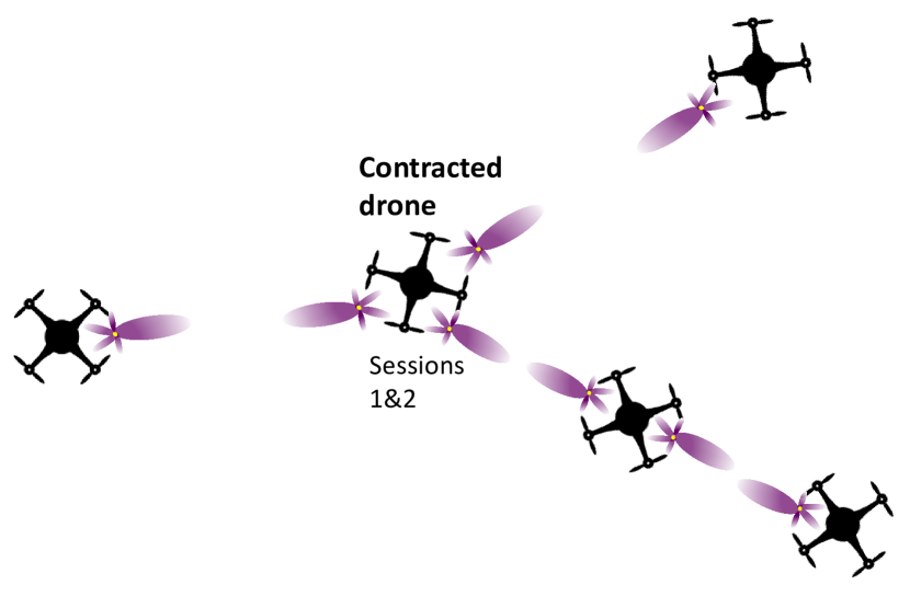
Angular optimization across sessions: SkyHaul then optimizes the deployment angularly by contracting (eliminating) relay UAVs with abundant radio capacity, and re-positioning the remaining relay UAVs so as to efficiently utilize their available radio capacity across sessions, all the while continuing to support the desired traffic demands (steps 16-35, Alg. 1). During this optimization in each sector, SkyHaul checks every pair of relay UAVs that belong to different sessions, whether they can be contracted, i.e., removed and replaced by a single UAV in a new, appropriate position and orientation, while supporting the aggregate traffic to both the original UAVs (steps 22-33, Alg. 1). When such a pair exists, the contraction is done and the two UAVs are replaced by the new UAV and the network configuration is updated (steps 27-30, Alg. 1); i.e., the neighborhood connectivity for the new UAV along with the routing of flow on its edges, as well as its (and neighbors’) orientation are updated.
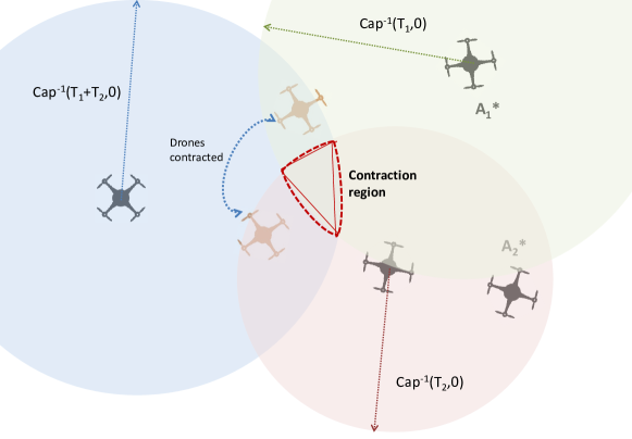
Contraction: Determining whether a pair of relay UAVs can be contracted () is a challenging problem in itself, given the infinite combinations of position and orientation possible for the new contracted UAV. SkyHaul accomplishes this efficiently in two steps: First, it identifies the largest contraction region possible by relaxing the constraint of orientation (i.e., assumes perfect orientation, ); then, selects a small number of boundary points of this region as potential contraction points (step 23 in Alg. 1). Finally, for each of these contraction points, it determines if there exists a feasible orientation for both the new contracted UAV as well as all its neighbors such that existing traffic demands can be satisfied (steps 24, 25 in Alg. 1).
The contraction region is determined by the polygon formed from the intersection of the circles – one for each neighbor of the pair of UAVs being contracted and whose radius corresponds to the maximum distance () that supports the traffic demand between that neighbor and the two UAVs as shown in Fig. 10. The corner points of this polygon along with its centroid are selected as a representative set of contraction points to be evaluated for a feasible orientation for routing. If multiple contraction points are feasible, then the one that is farthest from the GS UAV and closest to the application UAVs is selected (step 26 in Alg. 1); with contraction proceeding radially from the GS UAV, this increases the scope for subsequent optimization/contraction. In checking whether a feasible orientation exists (for demand satisfaction, ) for the new contracted UAV and all its neighbors, a simple optimization is solved for each of the UAVs under consideration.
The above optimization selects an orientation for UAV and a time sharing solution () for each of its sectors such that the maximum amount of its traffic demands can be satisfied. For a given orientation of the UAV (), this optimization can be decoupled across the UAV’s sectors (), where it becomes linear and can be solved individually (optimally) in each sector. Thus, the above optimization has the following closed-form solution.
| (2) | |||||
| (3) | |||||
| (4) |
In addition to contraction within each sector of the GS UAV, SkyHaul also explores contraction across the edges of adjacent sectors (sep 37 in Alg. 1). It executes the contraction procedure again within each virtual sector, where the latter consists of two adjacent sectors.
3.3 Performance Monitoring and Adaptation
SkyHaul adapts its backhaul network configuration from time-to-time to cater to the varying positions and traffic demands of application UAVs that are tracking the target event. It monitors the end-to-end throughput of each session at the GS along with the energy levels of UAVs. It triggers a network configuration update, when (i) the current demand satisfaction of any session drops below a certain threshold (balances responsiveness vs. session interruptions), (ii) UAVs need energy replenishment (when energy drops below ), or (iii) application UAVs have been reassigned to cover other areas (ROIs). SkyHaul first attempts to find a configuration with updates to only the yaws of the UAVs that carry traffic for the affected sessions (i.e., angular optimization without contraction), thereby avoiding UAV migrations. When this is not feasible, it executes a complete configuration update that might necessitate UAV migrations.
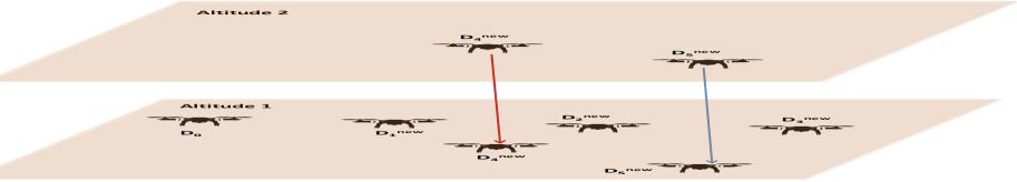
3.4 Seamless UAV Migration Plan
Whenever a configuration update is triggered, SkyHaul computes a new configuration (Alg. 1) based on current position and demands from application UAVs. However, the biggest challenge in realizing this new configuration lies in UAVs optimally (i.e., in least time) migrating from their old to new configurations (as shown in Fig. 11) without any collisions in the airspace. SkyHaul accomplishes this migration through a novel, optimal de-confliction flight control algorithm (Alg. 2) by leveraging various layers of altitude as described below. This same approach can be used to handle deployment of UAVs (relay and application) both during network initialization and later, as well as recovery of existing UAVs (for battery replacement) as special cases
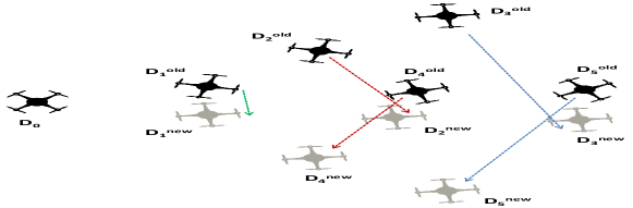
Flight plan for minimum migration time (Step 1): SkyHaul first determines the flight plan that would result in the least duration required to migrate to the new configuration, without accounting for potential conflicts between UAV movements during the migration (to be resolved in the second step). It accomplishes this by formulating the flight plan problem as a variant of the bipartite matching problem, where the objective is to determine the min-max bipartite matching assignment between old and new configuration UAV positions (with Euclidian distance as weights, serves as a proxy for migration time). The min-max objective helps us pick the migration plan that minimizes the maximum of the weights, i.e., longest time taken by any of the UAVs during their simultaneous migration.
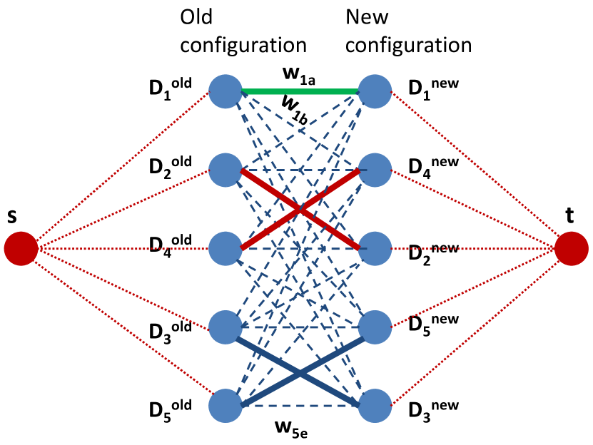
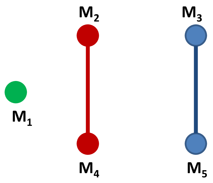
Migration algorithm: While algorithms exist for maximum or minimum weight bipartite matching, the variant of min-max bipartite matching (M2BM) has not been addressed in literature. To this end, we now provide an optimal algorithm to solve M2BM. The algorithm proceeds by forming a flow graph from the bipartite graph , using the same set of vertices but adding a source and sink that are connected to the vertices in and respectively. Then it sorts the edges in based on increasing weights and adds them one by one to . At each iteration, a max-flow algorithm is run between and on with all edges carrying a weight of one. The resulting max-flow solution yields a maximum matching between vertices and in . If the matching is perfect in , i.e., its size is equal to that of the vertex set of , then is the desired migration configuration (see Fig. 12). Otherwise, the next sorted edge from is added to and the process is repeated until a perfect matching is found. The resulting solution is optimal in that it takes the least time for configuration migration.
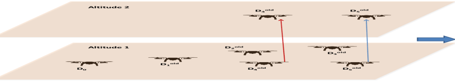
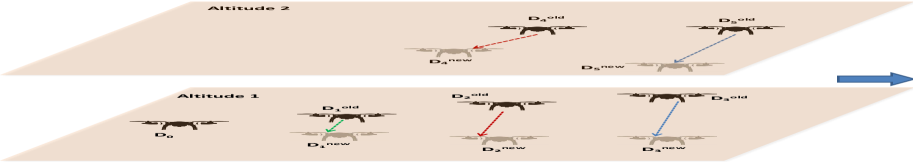
De-conflicting the flight plan (Steps 2-4): The migration solution does not account for potential conflicts/collisions in the airspace when UAVs migrate in tandem on the same Euclidian plane (i.e., when their migration paths cross). To deconflict such colliding migration paths, SkyHaul uses the layers of altitude available for migration (steps 2-4, Alg. 2). Specifically, SkyHaul creates a conflict graph , with the edges of the output matching , now serving as vertices () of , while edges in correspond to migration paths () that conflict in the Euclidian plane (e.g. paths that cross or come in close proximity of one another). SkyHaul then colors with the least possible colors (step 2, Alg. 2), and assigns migrations (vertices) with different colors to different altitudes to get a collision-free flight migration path (step 3, Alg. 2). Then, it executes the migration in a three step procedure as shown in Fig. 13 (step 4, Alg. 2): (i) move the UAVs (assigned to different altitudes) in altitude (z-axis) alone first, while retaining their position in the x-y plane; (ii) Then, allow the UAVs in different altitudes to move to their new position in the x-y plane as dictated by their new configuration; and (iii) finally, bring them all back to the original altitude for operation in the new configuration.
In practice, owing to Euclidian constraints and a migration solution targeting minimum duration, the conflict graph hardly has cliques of size three or more. This allows for at most three altitude layers (existing, one above, one below) needed to resolve the conflicts. Thus, the bulk of the time needed for configuration migration arises from moving to the new configuration at a prescribed altitude (time to move across altitude layers is relatively insignificant), which in turn is optimized by SkyHaul.
Impact of Altitude Changes: SkyHaul operates with UAVs on the same operating altitude. During UAV migration, SkyHaul may temporarily move the UAVs to different altitudes away from the SkyHaul operating altitude. This will temporarily disconnect the UAV from the SkyHaul mesh, and will reconnect upon UAV returning to the operating altitude. These temporary disconnections are short and do not impact the overall operation.
3.5 Performance and Time Complexity
Time Complexity: We first characterize the time complexity of SkyHaul’s configuration determination algorithm, Alg. 1. The complexity in the radial optimization comes from solving the convex optimization for initial deployment per session, which is , followed by orientation determination at each of the drones, which is . Here, and are the number of sessions and drones per sector of the GS drone. Given that this optimization is done in each of the GS drone’s (logical) sectors (total of ) independently, this results in a net complexity of . The key time consuming component in angular optimization arises from the contraction step, whose worst case complexity results when every pair of drones (belonging to different sessions) needs to be considered for contraction without success. This results in a complexity of , while the check of feasible orientation contributes another per pair considered, resulting in a net complexity of for angular optimization. Putting the two steps together, SkyHaul accomplishes network configuration determination with an efficient complexity of , where the cubic impact is only with respect to sessions and drones in a sector and not the whole network.
The time complexity of SkyHaul’s configuration migration algorithm, Alg. 2 is dominated by the computation of the migration plan itself. This in turn requires computing a max-flow solution for the network graph (with vertices, where ), whose edges are added incrementally. The complexity of the max-flow solution is , where is the number of edges (that varies incrementally from to ) and is the max-flow value, which in our case is the size of the perfect matching (). Hence, when accounting for all the sectors, this results in a net complexity of . We believe this can be reduced to by incrementally growing the augmenting path of the max-flow solution in each iteration without having to run the whole max-flow algorithm.
Performance: Given the hardness of the configuration computation problem, it is hard to establish a performance guarantee for Alg. 1. However, as we show in the evaluation section, SkyHaul delivers very efficient performance in practice – it is able to satisfy all the traffic demands of the target application at a deployment cost that is very close to that of a (minimum) Steiner point solution; the latter serving as a bound on the minimum number of drones needed to be deployed purely from a binary connectivity standpoint without accounting for mmWave constraints or traffic demands.
With respect to SkyHaul’s migration solution, we can establish the following performance.
SkyHaul determines an optimal migration plan in , where is the number of logical sectors (radios) at the GS drone, and is the number of drones deployed per sector.
Proof 3.1.
Having already shown the time complexity, this reduces to showing that Alg. 2 computes a perfect matching (of size ), whose maximum weight (migration time) among all its migrations is the minimum. By incrementally introducing edges, SkyHaul ensures that a maximum matching is found at every iteration. Hence, if there exists a perfect matching at any iteration, it will be found. Given the addition of edges in order of increasing weights, this automatically results in the smallest (max) weight for which a perfect matching is possible.
3.6 Leveraging Multiple Ground Stations
SkyHaul can be easily adapted to leverage multiple ground stations. Note that while multiple GSs bring additional capacity (entry/exit points) to the backhaul, they would also incur additional drone deployment for connectivity. The challenge is to leverage the appropriate number of GSs (and their capacity) to support the desired traffic demands of the application.
Given a set of potential GSs (and their ground locations), SkyHaul accomplishes this by incrementally picking one GS in each iteration, where the GS that yields the highest marginal utility () is chosen (from remaining GSs) and added to the network. GSs are added until desired traffic demands can be satisfied by the network.
In each iteration described above, SkyHaul needs to solve the backhaul deployment problem for a given number of GSs. Here, the traffic demands to/from the application drones are equally split to the different GSs. Then, SkyHaul finds the initial deployment of drones (using its radial optimization) with respect to each of the GSs in isolation. Then, it aggregates the deployment across all the GSs and contracts the backhaul drones (using its angular optimization) across both sessions and GSs jointly. This allows SkyHaul to determine an efficient backhaul deployment that is tailored to the positions of the GSs under consideration.
4 Implementation and Evaluation
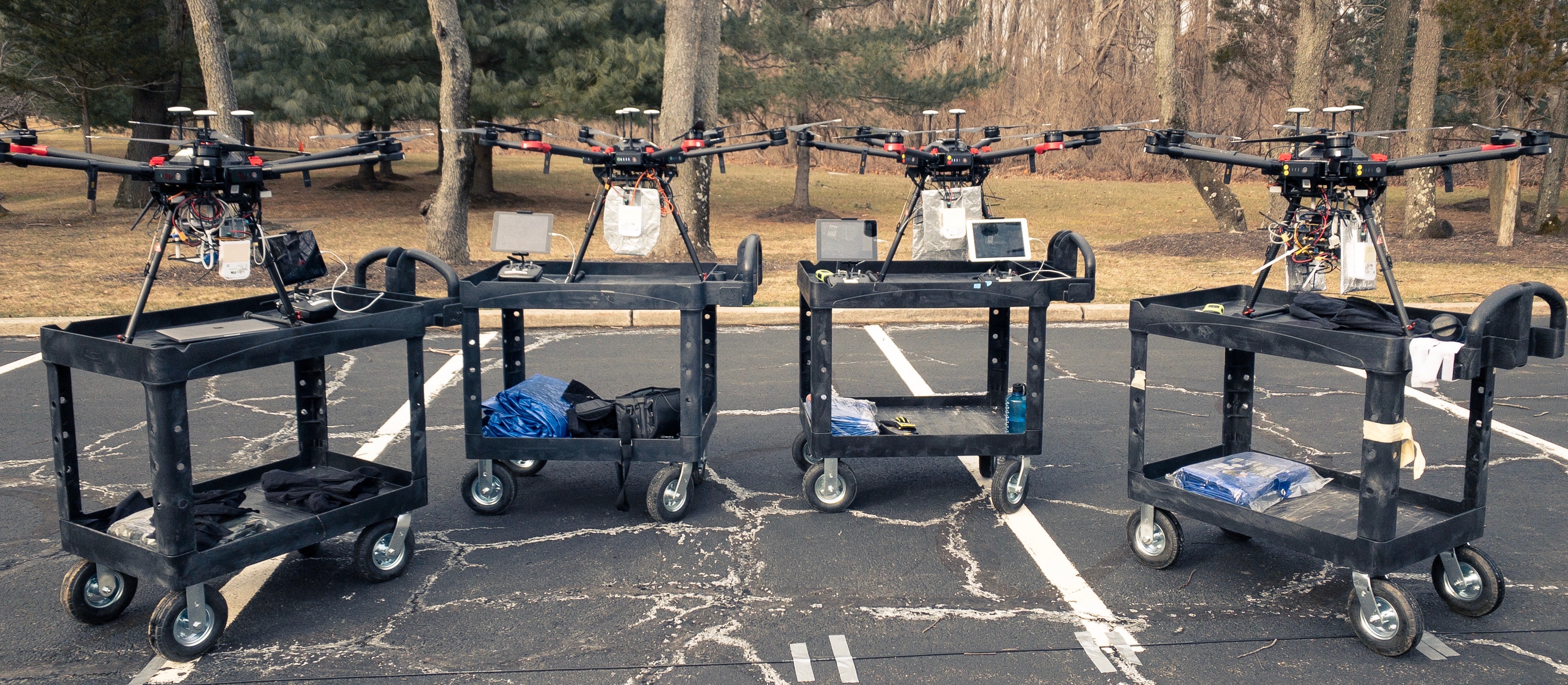
We implement SkyHaul on four DJI Matrice 600 Pro UAVs to demonstrate its performance in realistic flight conditions, and highlight its ability for autonomous reconfiguration of a multi-UAV network. To understand the merits of SkyHaul’s algorithms, we also study its performance in large scale topologies (more UAVs) through simulations in §5. Video demonstration of SkyHaul can be found at [15].
4.1 Implementation
AWS. SkyHaul controller is executed on an Amazon Web Services instance, and communicates with the UAVs via an LTE interface (through a smartphone). Each UAV continuously transmits all its telemetry data (i.e. GPS position, yaw, battery level etc) to the AWS instance and executes movement instructions that are sent back to them from SkyHaul controller. However, when cellular services are unavailable, the 60Ghz network itself can be used as a control channel, with the SkyHaul controller running on the Ground Station (GS) computer. The large bandwidth of the 60Ghz link ensures negligible overhead for communicating control information along with the actual data.
M600Pro. Each UAV is equipped with a single-board computer (SBC) with an Intel Core i7-6600U CPU running Ubuntu 18.04. The UAV is controlled from this SBC using DJI OnBoard SDK. We design and install role-specific payloads on the UAV platforms, one GS UAV, one relay UAV and two application UAVs (Fig. 14). The GS UAV has three 60GHz radios, one pointing downwards towards the GS, and two mounted horizontally to connect to the other UAVs. The relay UAV has two horizontally mounted radios and application UAVs have one radio and a 4K camera for live video-streaming. Each 60GHz radio is connected to the SBC via an ethernet port.
UAV power consumption: Each UAV has a flight time of 20 min and can carry a payload of max. 5Kg. Power consumed by on-board 60Ghz radios is negligible compared to the power required for the actual flight. Many long-endurance UAVs [23],[24],[25] with high-capacity batteries and flight times extending to many hours are already available for use.
4.2 SkyHaul– Evaluation
We first evaluate the impact of mmWave link throughput due to UAV mobility. Subsequently, we focus on evaluating SkyHaul, by running a series of experiments that show workings of the proposed algorithms under two realistic scenarios that enable (i) on-demand communication (wireless access), and (ii) sensing (live 4K video analytics), from application UAVs. We demonstrate SkyHaul’s ability to seamlessly maintain network performance under actual flight operations: The application UAVs move along a pre-determined path to emulate tracking of application dynamics (e.g. user movement, spread of forest fire), while SkyHaul continuously and autonomously positions the relay UAV to satisfy the high traffic demands of the application UAVs. We compare SkyHaul to a MinDrone baseline that only adjusts the yaw of the GS UAV to best maintain connectivity and share its multiple radios with the application UAVs, without using a relay UAV. This is analogous to most commercial solutions that currently exists.When the application UAVs start moving, MinDrone is unable to maintain the initial level of network throughput with either the application or the GS UAV.
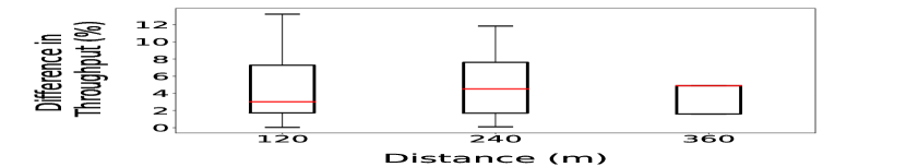
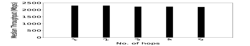
Link Performance vs. UAV mobility: The graph in Fig. 15 shows the difference in a link’s median UDP throughput when two UAVs are static (hovering), and when they are continuously mobile while maintaining a constant distance between them. The results are obtained for distances of 120m, 240m and 360m and for all relative UAV orientations (yaws) from to (in steps of ) for each of the distances. We do not observe a significant impact of UAV mobility on link throughput. This indicates that once the radios are oriented appropriately, small UAV vibrations and movements due to air turbulence can be handled by 802.11ad’s underlying beam selection algorithm. Additionally, we observe that the end-to-end throughput is not affected by the path-length (# of hops). Hence, extending coverage by adding multiple relay UAVs should not affect SkyHaul’s performance appreciably.
4.2.1 On-demand Wireless Access
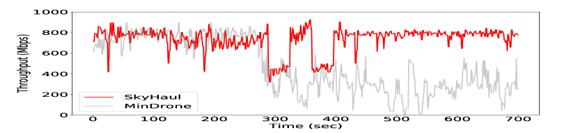
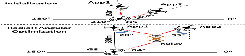
In order to emulate traffic load from a mobile small-cell (WiFi-AP/LTE), each application UAV generates 450Mbps UDP traffic using iperf3. We measure the actual received throughput at the GS. All the UAVs operate at 60m altitude. SkyHaul- Radial + Angular Optimization: In our first experiment, we initially place the application UAVs (APP1 and APP2) at radius and and respectively from the GS UAV (fig.16). With APP1 and APP2 capable of direct connectivity to the GS UAV, SkyHaul determines the optimal yaw for the GS UAV () and application UAVs (, and ) that allows net traffic demand from both the application UAVs to be satisfied by its same 60GHz radio. Since a relay UAV is not required yet, SkyHaul and MinDrone achieve a similar performance with an aggregate throughput of 800Mbps.
After couple of minutes, the application UAVs while maintaining their angular offsets (w.r.t. the GS UAV), start moving until they are away from the GS UAV. Once the throughput of APP1 and/or APP2 falls below a certain threshold (, 330Mbps), SkyHaul runs a configuration update through its radial+angular optimization to determine that while relay UAVs are needed to sustain service to either of the application UAVs, this can be achieved with a single relay UAV. As shown in Fig. 16, it launches a relay UAV and positions it at and 160m from the GS UAV. The orientation of the relay and application UAVs are then updated to , (APP1), (APP2), respectively, such that one of the relay UAV’s radios is used to jointly serve both the application UAVs, while the other provides connectivity to the GS UAV, latter’s yaw being . During this dynamic event, we observe a sharp throughput degradation in Fig. 16 that results from disconnection as well as re-connection through the relay UAV. However, after SkyHaul completes its reconfiguration, the aggregate throughput is immediately restored to 800Mbps. Without the aid of a relay UAV, MinDrone is unable to sustain the application demands, providing an aggregate throughput of at most 400Mbps, while reaching a low of 200Mbps.
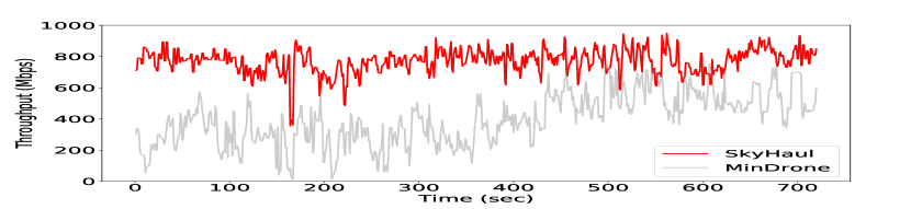
SkyHaul- Re-configuration and Load Balancing: In the next experiment, we initially place both APP1 and APP2 360m away from the GS UAV, with both being served by a relay UAV placed as shown in the Fig 17. While APP1 remains static, APP2 starts moving closer to the GS UAV until it is apart (refer to Fig. 17). SkyHaul determines that while GS UAV can directly connect and support APP2’s traffic demands, APP1 still needs a relay UAV. It computes the updated configuration, resulting in relay UAV moving to 165m, at from GS UAV to serve APP1 alone, while the GS UAV updates its yaw to allowing it to use two of its radios, each serving one application UAV. The application and relay UAVs update yaws to , and , respectively. This shows SkyHaul’s ability to efficiently leverage radios from various UAVs in the network to best address application requirements.
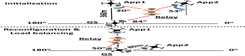
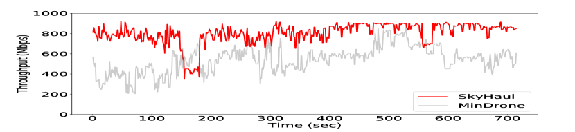
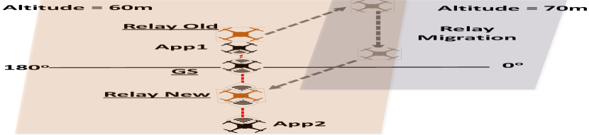
SkyHaul- Configuration Migration: In our third experiment, we initialize APP1 and APP2 to be stationed at distances of 360m () and 100m () from the GS UAV, respectively. SkyHaul’s initial configuration requires App1 to be served via a relay UAV and App2 can connect directly to the GS UAV. After a minute, we simultaneously move APP2 away from the GS UAV to 360m,, and APP1 closer towards the GS UAV to a distance of . With APP1 capable of direct connectivity to the GS UAV, SkyHaul determines that the relay UAV needs to be re-purposed for APP2. However, this requires a flight plan, since the path of APP1 conflicts with that of the relay UAV, and the latter’s with the GS UAV. SkyHaul employs its efficient route-planning solution to determine an optimal (fast) collision-free migration of the relay UAV towards APP2: the relay UAV first ascends to a different altitude of 70m (10m above operating altitude of 60m) to resolve conflicts; while the relay UAV moves to its new position at 70m, the two application UAVs move to their new positions at 60m simultaneously; then the relay UAV reduces its altitude back to operational height of , while retaining its position in the plane. The whole migration process is executed autonomously with no human input. At this point, SkyHaul updates the yaw of APP2, relay and GS UAVs to such that both application UAVs are effectively served. The throughput result in Fig 18 captures this transition, as the net-throughput decreases before being restored after re-connection. MinDrone is unable to accomplish such an adaptation and thus, suffers a drastic drop in throughput to about 500Mbps over the same duration.
4.2.2 Cloud-Based 4K Video Analytics
We demonstrate SkyHaul’s capability in aerial video surveillance applications by conducting real-time video analytics on multiple 4K 60FPS video streams sent from application UAVs to the GS UAV. Application UAVs follow the same flight path as in §4.2.1, while each sends a video stream using FFMPEG to the GS, which are then forwarded to our local GPU running YOLO3 [26] object detection algorithm.
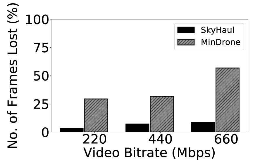
Received Video Quality. Fig. 19(a) compares the per-frame Structural SIMilarity Index (SSIM) [27] of the video stream, encoded at different bitrates, received using SkyHaul and MinDrone w.r.t. the original stream recorded locally at each application UAV. Compared to traditional metrics – PSNR and MSE, SSIM metric takes into account more features between the original and the received images for quality comparison. SSIM considers three things: (a) Similarity in luminance, (b) Similarity in contrast, and (c) Correlation between the two images. The SSIM index is a value between 0 (no similarity) and 1 (100% similar) — the higher the SSIM value, the “cleaner” the received image and thus, the better the object detection accuracy.
Observe that SkyHaul achieves significantly higher SSIM values than MinDrone at all video bitrates. While SkyHaul achieves an SSIM index of 1 for over 80% of the frames with a bitrate of 660 Mbps, MinDrone suffers early even at 220 Mbps bitrate, with only 15% of frames achieving an SSIM score of over 0.8. As seen in Fig. 19(b), higher bandwidth of the backhaul also helps to significantly reduce the number of lost frames in SkyHaul, which directly impacts on improving the accuracy of the object detection task.

Object Detection. We use a cloud server instance with a 32 core Intel E5-2686v4 CPU and four NVIDIA Tesla V100 GPUs with SkyHaul for real-time video analytics. Video streams from the application UAV are sent to the cloud instance from the ground station for object detection.
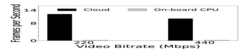
SkyHaul accelerates video analytics: Fig. 20(a) shows if we rely only on on-UAV compute resources, object detection proceeds at 0.2 frames-per-second (FPS). However, with SkyHaul’s ability to maintain high bandwidth links to the application UAVs, we achieve over 50 speed-up: Object detection proceeds at up to 13FPS with a 440Mbps stream.
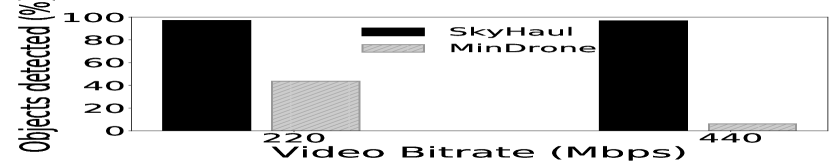
SkyHaul increases object detection accuracy: SkyHaul delivers significantly fewer dropped frames to the cloud instance than MinDrone. Fig. 20(b) shows that as a result, we achieve 97% object detection accuracy with SkyHaul (w.r.t. the lossless video recorded on the UAV) at all bitrates while MinDrone can only achieve as low as 10% detection accuracy (on a 440Mbps stream) due to lost frame data.
5 Large Scale Simulations
The devastating forest fires in Paradise, CA [28, 29], showed that unavailability of traditional communication infrastructure cell-towers can hamper first responders’ rescue operations. We simulate deploying SkyHaul to provide backhaul connectivity to UAV based on-demand small-cells deployed during such emergencies. To construct realistic topologies for application UAVs, we use the Paradise city map showing evacuation zones [30]. Assuming each zone has at least one ground station at the center, we generate 140 topologies (14 zones, 10 per zone) each with 5 (sparse deployment), 10 (moderate) and 20 (dense deployment) application UAVs within each zone. We consider 3 radios per relay UAV, and the ground station to have enough radio capacity to satisfy the net traffic demand of all application UAVs. Throughput requirement of each application UAV in each run is randomized to be between 100Mbps-1Gbps.
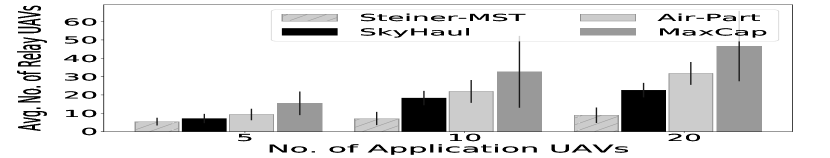
We compare the performance of SkyHaul against the following baseline algorithms: (a)Steiner-MST: Finding Steiner trees that employ a minimal number of Steiner points (Relay UAVs) to connect the application UAVs with a bounded edge (transmission) length, is a NP-hard problem. Steiner-MST provides a heuristic construction by finding the minimum spanning tree, connecting application UAVs to the GS UAV, then adding Relay UAVs to the paths computed based on the maximum communication length of each UAV. However, such Steiner solutions do not account for routing of traffic demands. (b)MaxCap: While Steiner-MST optimizes for connectivity with reduced UAV budget, MaxCap optimizes for capacity, to provide 100% traffic satisfaction to each application UAV, without optimizing the number of relay UAVs employed. Here, the Relay UAV deployment is optimized for each application UAV in isolation, while accounting for other application UAVs that are sharing the same radio of the GS UAV. (c)Air-Part: This is a subset of SkyHaul with only the radial optimization (§3.2), i.e. no angular optimization across multiple sessions.
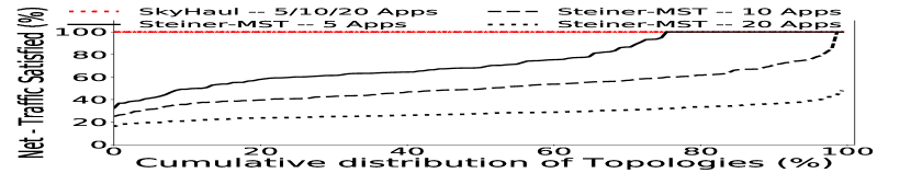
Fig. 21 shows the CDFs of traffic satisfaction (Net throughput / Net traffic demand) and average number of relay UAVs used by each algorithm.While Steiner-MST uses fewest UAVs, it is unable to satisfy the traffic requirement (Only 75%, 45% and 22% traffic satisfied in median case for 5, 10 and 20 application UAVs, respectively). On the other hand, MaxCap ensures 100% traffic satisfaction, but requires nearly four times the number of relay UAVs (for 20 Application UAVs) than Steiner-MST. In contrast, both SkyHaul and Air-Part strike a good balance between the number of relay UAVs needed and ensuring 100% traffic satisfaction. While the radial optimization in Air-Part itself employs 30% - 50% fewer UAVs than the MaxCap, the angular contraction in SkyHaul optimizes deployment across sessions to reduce the UAVs required by 15%-40%, all while ensuring 100% traffic satisfaction.
6 Related Work
60GHz Link Performance: Many studies have focused on analyzing 60Ghz channel performance. Short-range 60Ghz link models for indoor locations [31, 32] are not directly applicable for our reconfigurable environment. Outdoor 60Ghz models [33, 34] developed using special hardwares like horn antennas and dedicated channel sounders do not capture the mobility of UAVs and hence the orientation of its mmWave radios on coarse time-scale network deployment decisions.
UAV based networks: Apart from the popular high-altitude UAV network projects [7, 35], there has been recent interest in exploring solutions for low-altitude UAV-based cellular networks [36, 37]. [38, 39, 3, 4] use UAVs as stand-alone base stations, focusing on UAV placement for improving cellular coverage to ground users. SkyHaul has a complementary focus in establishing a robust, mmWave-backhaul solution that can support the traffic demands of such cellular/WiFi access solutions. [40, 41, 42] target multi-UAV networks, relying on numerical models and omni-directionality of the sub-6GHz RF technologies. This simplifies the UAV-deployment problem, while being unable to support high-bandwidth (mmWave) and the dynamics of applications. [43] investigates effects of different types of wireless backhauls offering various data rates on the number of ground users.
Routing algorithms: Routing in multi-hop networks has been studied extensively [10, 11, 12], with a limited focus on specific routing algorithms for Flying Adhoc Networks [44]. However, all these algorithms assume a pre-determined topology. This being not the case in SkyHaul, requires a joint optimization of both routing and topology.
7 Conclusion
In this work, we presented the design and deployment of SkyHaul– an autonomous, self-organizing, mmWave-meshed, multi-UAV network that is capable of safely adapting itself to cater to highly dynamic applications and events. Through extensive real-world experiments, and large-scale simulations, we demonstrated the workings of SkyHaul.
SkyHaul for city-wide coverage: In order to establish a city-wide backhaul network, the range of each mmWave radio needs to be longer than 360m supported in this work. However, radio products [45] that can extend range upto 1km are already available. SkyHaul can be easily scaled-up to cover cities using such long-range radios while reusing its existing algorithms.
References
- [1] US Ignite, “Drone-Supported Emergency Management,” https://www.us-ignite.org/apps/drone-supported-emergency-management/.
- [2] Utah Ignite, “Utah Ignite – Smart cities Smart Gigabit community,” http://www.utahignite.com/.
- [3] Ayon Chakraborty, Eugene Chai, Karthikeyan Sundaresan, Amir Khojastepour, and Sampath Rangarajan, “Skyran: A self-organizing lte ran in the sky,” in Proceedings of the 14th International Conference on Emerging Networking EXperiments and Technologies, New York, NY, USA, 2018, CoNEXT ’18, pp. 280–292, ACM.
- [4] Mehrdad Moradi, Karthikeyan Sundaresan, Eugene Chai, Sampath Rangarajan, and Z. Morley Mao, “Skycore: Moving core to the edge for untethered and reliable uav-based lte networks,” in Proceedings of the 24th Annual International Conference on Mobile Computing and Networking, New York, NY, USA, 2018, MobiCom ’18, pp. 35–49, ACM.
- [5] Qualcomm Technologies, Inc., “VR and AR pushing connectivity limits,” https://www.qualcomm.com/media/documents/files/vr-and-ar-pushing-connectivity-limits.pdf.
- [6] Arthur Holland Michel, “Amazon’s Drone Patents,” https://dronecenter.bard.edu/files/2017/09/CSD-Amazons-Drone-Patents-1.pdf.
- [7] Alphabet Inc.,, “Project Loon,” https://x.company/loon/., 2015.
- [8] Fox, “Fox sports,” https://www.foxsports.com/presspass/latest-news/2018/02/15/tethered-UAV-record-number-car-cameras-highlight-fox-sports-15th-daytona-500-broadcast.
- [9] Red, “Red.com,” https://www.red.com/recording-time.
- [10] T. Clausen and P. Jacquet, “Optimized link state routing protocol (olsr),” vol. 20, no. 3, 2003.
- [11] Richard Draves, Jitendra Padhye, and Brian Zill, “Routing in multi-radio, multi-hop wireless mesh networks,” in Proceedings of the 10th Annual International Conference on Mobile Computing and Networking, New York, NY, USA, 2004, MobiCom ’04, pp. 114–128, ACM.
- [12] Douglas S. J. De Couto, Daniel Aguayo, John Bicket, and Robert Morris, “A high-throughput path metric for multi-hop wireless routing,” in Proceedings of the 9th Annual International Conference on Mobile Computing and Networking, New York, NY, USA, 2003, MobiCom ’03, pp. 134–146, ACM.
- [13] Mikrotik, “Mikrotik,” https://mikrotik.com/product/wap_60g.
- [14] Amazon, “Amazon web service,” https://aws.amazon.com/.
- [15] “Skyhaul demonstration flight,” https://tinyurl.com/twjcksz.
- [16] E. Torkildson, H. Zhang, and U. Madhow, “Channel modeling for millimeter wave mimo,” in 2010 Information Theory and Applications Workshop (ITA), 2010, pp. 1–8.
- [17] T. S. Rappaport, Y. Xing, G. R. MacCartney, A. F. Molisch, E. Mellios, and J. Zhang, “Overview of millimeter wave communications for fifth-generation (5g) wireless networks—with a focus on propagation models,” IEEE Transactions on Antennas and Propagation, vol. 65, no. 12, pp. 6213–6230, 2017.
- [18] S. Shahsavari, M. A. A. Khojastepour, and E. Erkip, “Beam training optimization in millimeter-wave systems under beamwidth, modulation and coding constraints,” in 2019 IEEE 30th Annual International Symposium on Personal, Indoor and Mobile Radio Communications (PIMRC), 2019, pp. 1–7.
- [19] Shahram Shahsavari and Elza Erkip, “Robust beam tracking and data communication in millimeter wave mobile networks,” 2019.
- [20] Muhammad Kumail Haider and Edward W. Knightly, “Mobility resilience and overhead constrained adaptation in directional 60 ghz wlans: Protocol design and system implementation,” in Proceedings of the 17th ACM International Symposium on Mobile Ad Hoc Networking and Computing, New York, NY, USA, 2016, MobiHoc ’16, p. 61–70, Association for Computing Machinery.
- [21] Digital Trends, “7 Drones that can stay airborne for hours — and the tech that makes it possible,” https://www.digitaltrends.com/cool-tech/drones-with-super-long-flight-times/.
- [22] Donghui chen, Ding-Zhu Du, xiao-dong Hu, guo-hui Lin, Lusheng Wang, and guoliang Xue, “Approximations for steiner trees with minimum number of steiner points,” Journal of Global Optimization, vol. 18, no. 1, pp. 17–33, Sep 2000.
- [23] Skyfront, “Long endurance Drone,” https://skyfront.com/.
- [24] Quaternium, “Hybrid Drone,” http://www.quaternium.com/.
- [25] UAV Factory, “Long endurance UAS, UAVs and subsystems,” https://www.unmannedsystemstechnology.com/company/uav-factory/.
- [26] Joseph Redmon, Santosh Kumar Divvala, Ross B. Girshick, and Ali Farhadi, “You only look once: Unified, real-time object detection,” CoRR, vol. abs/1506.02640, 2015.
- [27] and A. C. Bovik, H. R. Sheikh, and E. P. Simoncelli, “Image quality assessment: from error visibility to structural similarity,” IEEE Transactions on Image Processing, vol. 13, no. 4, pp. 600–612, April 2004.
- [28] Los Angeles Times, “Paradise City Forest Fires,” https://www.latimes.com/local/california/la-me-camp-fire-deathtrap-20181230-story.html, 2018.
- [29] The Guardian, “Paradise City Forest Fires,” https://www.theguardian.com/environment/2018/dec/20/last-day-in-paradise-california-deadliest-fire-untold-story-survivors, 2018.
- [30] City of Paradise, “Paradise, ca,” https://www.townofparadise.com/index.php/17-news-events/248-evacuation-zones.
- [31] P. F. M. Smulders, “Statistical characterization of 60-ghz indoor radio channels,” Transactions on Antennas and Propagation, vol. 57, no. 10, pp. 2820–2829, Oct. 2009.
- [32] S. K. Saha, T. Siddiqui, D. Koutsonikolas, A. Loch, J. Widmer, and R. Sridhar, “A detailed look into power consumption of commodity 60 ghz devices,” in 2017 IEEE 18th International Symposium on A World of Wireless, Mobile and Multimedia Networks (WoWMoM), June 2017, pp. 1–10.
- [33] Thomas Nitsche, Guillermo Bielsa, Irene Tejado, Adrian Loch, and Joerg Widmer, “Boon and bane of 60 ghz networks: practical insights into beamforming, interference, and frame level operation,” in ACM CoNEXT 2015, 12 2015, pp. 1–13.
- [34] Muhammad Kumail Haider and Edward W. Knightly, “Mobility resilience and overhead constrained adaptation in directional 60 ghz wlans: Protocol design and system implementation,” in Proceedings of the 17th ACM International Symposium on Mobile Ad Hoc Networking and Computing, New York, NY, USA, 2016, MobiHoc ’16, pp. 61–70, ACM.
- [35] Facebook, “Facebook Project Aquilla,” https://code.facebook.com/posts/348442828901047/aquila-what-s-next-for-high-altitude-connectivity-/.
- [36] ATT networks, “ATT Cell On Wings,” http://about.att.com/innovationblog/cows_fly.
- [37] Verizon networks, “Verizon cell on wings,” ”https://newatlas.com/verizon-drones-internet-trials/45818/.
- [38] M. Mozaffari, W. Saad, M. Bennis, and M. Debbah, “Efficient deployment of multiple unmanned aerial vehicles for optimal wireless coverage,” IEEE Communications Letters, vol. 20, no. 8, pp. 1647–1650, Aug 2016.
- [39] J. Modares, F. Ghanei, N. Mastronarde, and K. Dantu, “Ub-anc planner: Energy efficient coverage path planning with multiple drones,” in 2017 IEEE International Conference on Robotics and Automation (ICRA), May 2017, pp. 6182–6189.
- [40] A Guillen-Perez and M.D Cano, “Flying ad hoc networks: A new domain for network communications,” 2018, Sensors, pp. 958–963.
- [41] L. R. Pinto, A. Moreira, L. Almeida, and A. Rowe, “Characterizing multihop aerial networks of cots multirotors,” IEEE Transactions on Industrial Informatics, vol. 13, no. 2, pp. 898–906, April 2017.
- [42] Sérgio Sabino and António Grilo, “Topology control of unmanned aerial vehicle (uav) mesh networks: A multi-objective evolutionary algorithm approach,” in Proceedings of the 4th ACM Workshop on Micro Aerial Vehicle Networks, Systems, and Applications, New York, NY, USA, 2018, DroNet’18, pp. 45–50, ACM.
- [43] E. Kalantari, M. Z. Shakir, H. Yanikomeroglu, and A. Yongacoglu, “Backhaul-aware robust 3d drone placement in 5g+ wireless networks,” in 2017 IEEE International Conference on Communications Workshops (ICC Workshops), May 2017, pp. 109–114.
- [44] Ozgur Koray Sahingoz, “Networking models in flying ad-hoc networks (FANETs): Concepts and challenges,” Journal of Intelligent & Robotic Systems, vol. 74, no. 1-2, pp. 513–527, oct 2013.
- [45] Mikrotik, “Long range 60ghz radio,” https://mikrotik.com/product/lhg_lite60.