Multipole analysis of substrate-supported dielectric nanoresonator arrays with T-matrix method
Abstract
Substrates, and layered media in general, are ubiquitous, affect the properties of whatever is in their vicinity, and their influence is, in an arbitrary framework, challenging to quantify analytically, especially for large arrays which escape explicit numerical treatment due to the computational burden. In this work, we develop a versatile T-matrix based framework in which we generalize the coupled multipole model towards arbitrarily high multipole orders and substrate-supported arrays. It allows us to study substrate-supported random/amorphous arrays of high index dielectric nanoparticles which are of wide interest due to relatively low losses and a highly tunable optical response, making them promising elements for nanophotonic devices. We discuss how multipole coupling rules evolve in the presence of a substrate in amorphous arrays for three interaction mechanisms: direct coupling between particles, substrate-mediated interparticle coupling and substrate-mediated self-coupling. We show the interplay between array density, distance from the substrate and its refractive in determining the optical response of an array. As an example, we use this framework to analyze refractometric sensing with substrate-supported arrays and demonstrate that the substrate plays a crucial role in determining the array sensitivity.
I Introduction
High index dielectric nanoresonators are used as building blocks of novel photonic devices such as photonically enhanced photovoltaic cells, biomolecule sensors and flat analogues of conventional optical devices called metasurfaces [1]. The interest in high index dielectric nanoresonators stems from the fact that they support both electric and magnetic resonances in simple geometries such as spheres or disks, which provides further tunability of the optical response [2]. Also, dielectric nanoresonators are less susceptible to losses and they are more compatible with the CMOS standard of modern electronics than plasmonic counterparts [1].
A convenient way to express and analyze the fields scattered by nanoresonators is by multipole expansion. The far-field characteristic of the optical response of an antenna is related to the interference of its multipole fields. Manipulation of these multipole moments can, for example, lead to unidirectional scattering via so-called generalized Kerker effects [3]. Tailored, directional scattering is essential for nonlinear photonics with dielectric nanoresonators and design of Huygens metasurfaces, which exploit Kerker effects to obtain almost ideal Huygens sources [4]. The conditions for achieving directional scattering are almost exclusively expressed using multipole moments. Notably, while small particles are usually associated with dipole moments, higher-order multipoles are also important and, upon careful design of nanoresonator geometry, can be even dominant in its scattering spectrum [5].
The next step from utilizing a single antenna for a given purpose is to arrange nanoresonators into an array, which predominantly takes the form of a two-dimensional construct. Its optical response is then determined by an interplay between the single-particle response, multiple scattering, and interference of the emitted fields. Multiple scattering leads to radiative coupling of multipole moments of the nanoresonators within an array and is addressed by solving a set of self-consistent equations for these moments.
The coupled multipole approach is often used to determine the optical response of periodic arrays of nanoresonators. It retains the physical interpretation of the inner working of the array and begets an intuitive understanding of the properties, such as shifting of the antenna resonances, broadening of the peaks due to near-field coupling, or the characteristic feature of periodic arrays in the form of lattice resonances [6]. It also demonstrates that different multipoles are affected in distinct manners by tuning the periodicity of an array in orthogonal directions. By virtue of this fact, electric and magnetic dipole resonance wavelengths can be tuned independently, modifying the resonance overlap condition [7].
An alternative route towards manipulation of interparticle coupling in two-dimensional arrays is by using amorphous arrays, which are random with a constraint on the minimal separation between nanoresonators. This constraint introduces short range position correlation and long range disorder. The randomness eliminates lattice resonances and the optical response is qualitatively similar to that of a single nanoresonator. At the same time, interparticle coupling modifies the optical response and the minimal center-to-center (CC) distance between nanoresonators. The CC distance, which is closely related to the array density, plays a similar role in tailoring intra-array coupling as does the (sub-diffraction) lattice in periodic arrays. The optical properties affected by the choice of minimal center-to-center distance include resonance wavelength and quality factor [8] as well as the scattering-to-absorption cross-section ratio [9], to name a few. We have recently shown that those density-driven effects render the minimal CC distance a useful handle to control electromagnetic coupling in amorphous arrays for applications such as refractometric sensing, directional scattering and solar energy harvesting [10].
The versatility of the coupled multipole model stems from that it provides semi-analytical solutions for the multipole moments of infinite nanoresonator arrays in both periodic and amorphous arrangements [10]. To that end, first, propagators of each multipole must be derived and a general coupled multipole equation system must be proposed. Then, an assumption that the nanoparticle array is infinite is introduced. For periodic arrays this renders the multipole moments of all the particles identical and reduces the inverse problem to single particle multipoles coupled to their infinite multipole neighbourhood via so-called lattice sums. The procedure is exactly the same for amorphous arrays [8, 11] except for the fact, that in random arrays each nanoparticle has a unique neighbourhood and therefore an average, continuous multipole film is considered as the nanoparticle’s neighbourhood. In recent literature, there are several examples of lattice sum derivations including electric and magnetic dipoles, dipole-quadrupole coupling for both periodic arrays [12, 13] and amorphous arrays [8, 14, 11, 10].
A substantial disadvantage of the coupled multipole model for nanoresonator arrays is that it provides a solution for an idealized situation in which the nanoresonators are embedded in a homogenous environment. However, in experimental conditions two-dimensional nanoresonator arrays are almost exclusively fabricated on a substrate, which may substantially impact the optical response of the system. One prominent example of the substrate-related effects is exceptional field enhancement observed in a nanoparticle-on-mirror system, in which a plasmonic or a dielectric nanoresonator is placed in close vicinity of a metallic mirror [15, 16]. The coupling between the nanoresonator and its image results in a large field enhancement and confinement utilized for realizing strong light-matter coupling experiments. Simultaneously, from a mathematical point of view the presence of a substrate is also known to influence the multipole expansion of the scattered fields [17, 18]. The scattered electric dipole field can be reflected off the substrate and trigger a magnetic dipole response and vice-versa, leading to the magnetoelectric coupling [19]. As a consequence, substrate-induced bianisotropy can be observed [20]. Magnetoelectric coupling also leads to exceptionally strong polarization sensitivity of the optical response of dielectric nanoresonators placed on a metallic film [21]. Finally, the presence of substrate is known to modify the back-reflection Kerker conditions [22, 23] and circular dichroic spectrum of a nanoresonator [24, 25, 26].
Here, we exploit the recent advantages in the transition matrix (T-matrix) method to address the generalization of the coupled multipole model towards arbitrarily high multipole orders and substrate-supported arrays. The T-matrix is closely related to Cartesian multipole moments and the two formulations (superposition T-matrix and Green function based) of the coupled multipole model are equivalent [27, 28]. Both require the evaluation of the so-called Sommerfeld integrals in order to calculate the reflected fields. This approach has been used for instance to evaluate magnetoelectric coupling in a single dielectric particle [19] or substrate-supported single nanoresonator optical response in the discrete dipole approximation [29]. Recently, a general superposition T-matrix method for nanoresonators in a layered medium has been proposed [30]. Here, we formulate the infinite array approximation, which provides the effective (average) multipole moments of a nanoresonator in an array. We focus on amorphous arrays as they are challenging to tackle with other methods and are an interesting alternative to periodic arrays, especially since many bottom-up, self-assembly methods exist to fabricate such random structures. However, the model and some of the conclusions are also applicable to periodic arrays.
This work is structured as follows. First, we derive the model and verify it numerically with the superposition T-matrix and finite-difference time-domain (FDTD) methods. Then, we study multipole coupling in a substrate-supported array. We provide general multipole coupling rules that can be applied to any array with central symmetry. We exemplify these rules and show generalized magnetoelectric coupling that includes higher-order multipoles. Finally, we study the parameters influencing substrate-mediated multipole coupling and provide an example of electromagnetic coupling effects applied to refractometric sensing.
II Amorphous array of particles on a plane substrate
The external field acting onto a particle and its scattered field at position can be expanded into vector spherical wave functions (VSWFs) as follows
| (1) |
| (2) |
where is the wavenumber in a given medium with index , is the wavelength, and we follow [31] in the definitions of VSWFs, which for convenience are summarized in Appendix A. The T-matrix relates the expansion coefficients of the external () and scattered fields () in terms of radiating vector spherical wave functions (VSWF) [31]
| (3) |
which is simplified as . Here, the T-matrices are calculated using the null-field method with discrete sources which is an efficient method of evaluating single particle scattering properties.
In the case of coupled nanoantennas embedded in a stratified medium the equation describing the response of any scatterer has to be extended [32] to include the scattered field of all other scatterers as
| (4) |
Here, the scattered field from the other scatterers () has to be expressed in regular rather than radiating VSWFs in order to conveniently consider this field as a contribution to the incident field driving scatterer . The relation that defines the direct (subscript ) coupling matrix is therefore
| (5) |
where is the direct coupling matrix (which is present also in a homogeneous environment). A similar expression can be defined for the scattered field from scatterer reflected (subscript ) off the substrate
| (6) |
where is the substrate-mediated coupling matrix. The definitions of the coupling matrix terms are presented in Appendix B.
By combining the definitions of the coupling matrices with Eq. 4 we obtain
| (7) |
We separate out the reflected self-coupling of scatterer with itself () from substrate-mediated interparticle coupling () and under the summation we explicitly introduce the dependence of and on cylindrical coordinates and drop the superscripts
| (8) |
where is a vector in cylindrical coordinates from scatterer to .
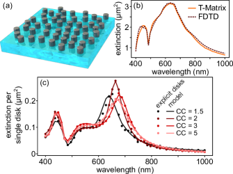
To reduce the many-particle problem to an effective single-particle one, we make use of the nature of amorphous arrays (Fig. 1a) that while the neighborhood of any given resonator is unique, the particle distribution in the array is given by a pair correlation function (PCF) , where is the minimal center-to-center distance. This stochastic similarity of a random array allows us to replace the discrete particle properties by an effective, continuous film of multipoles of average properties given by and density by . Thus, we can write
| (9) |
where is the particle number density. Here, we parametrize the spatial distribution by using the minimal center-to-center distance , where is the nanodisk diameter (the disk’s thickness is ) and is a dimensionless parameter. We multiply the integral function by an exponentially decaying term with small constant to make the integrals well defined. Physically, this corresponds to an infinite array illuminated by a finite, slowly decaying beam.
The equation can be further simplified by analyzing the angular integral. The coupling matrix can be factorized into radial and angular terms
| (10) |
The angular probability distribution of finding a neighbouring particle is uniform, which leads to the following result
| (11) |
for and zero otherwise. Next, we define the effective direct coupling matrix as
| (12) |
and the effective substrate-mediated (reflected) coupling as
| (13) |
The radial part of the integral is evaluated and integrated numerically. We utilize the expression for the PCF of amorphous arrays from [14]. In order to evaluate the improper integrals we truncate the integral at certain interparticle distance. Consequently, there are three parameters that determine the accuracy of the integration: resolution of the radial grid, damping of the oscillating part of the integral, and truncation distance. Equation 11 is then solved for the scattering coefficients by matrix inversion
| (14) |
Finally, the extinction cross-section is evaluated as a sum of individual VSWFs contributions [31]
| (15) |
Having outlined the model, we verify it numerically by calculating optical properties of substrate-supported amorphous arrays of high index dielectric nanodisks illuminated by a normally incident plane wave. Modelling of anisotropic scatterers with the T-matrix method is problematic due to the so-called Rayleigh hypothesis that states that the fields calculated with the T-matrix method are valid only outside the circumscribing sphere of the scatterer. In our particular case of dielectric nanodisks supported by a substrate, such a sphere crosses the substrate and therefore the Rayleigh hypothesis is not fulfilled for the particle interacting with its image. However, it has been recently shown that this limitation can be circumvented by relying on the conditional convergence of plane wave expansion of VSWFs truncated at a certain wave vector [33]. Here, we utilize the relation between the truncation wave vector and the truncation multipole order from [33] to simulate anisotropic nanoresonators. Because of the fact that full-wave Maxwell equation solvers based on finite-element or FDTD methods are not capable of simulating random arrays of realistic size, we validate our approach in two steps.
First, we verify the validity of the plane-wave expansion for substrate-supported arrays by comparing the extinction cross-section spectrum obtained with the T-matrix method (open-source python code SMUTHI [30, 32]) for an amorphous array composed of 24 crystalline silicon (c-Si) [34] nanodisks ( nm, nm, ) with an FDTD simulation (Lumerical FDTD solutions) for the same array (Fig. 1b). The T-matrix results agree well with those given by the FDTD method.
Next, we compare the results of superposition T-matrix to our effective model. We simulate arrays with 1751 particles made of c-Si drawn using random sequential adsorption [35] on a substrate at selected CC values. This number of disks is sufficient for yielding spectra which do not change significantly for different realizations of an amorphous array. For low density (high ) the optical response is almost density independent [14], as it should, since the arrays tend to well-separated quasi-single disks. However, as plotted in Fig. 1c, for dense arrays significant deviation from the single particle response is observed [8, 10]. The obtained agreement between the two methods (effective and superposition T-matrix) is maintained even for dense arrays, leading to the conclusion that we can indeed predict the optical spectra of substrate-supported arrays using our effective approach, which is orders of magnitude faster than the direct superposition T-matrix approach.
III Multipole coupling selection rules
Occurrence of multipole coupling depends on three factors: on the coupling matrix form for a given particle environment, on symmetries in the angular distribution of particles and on the polarization of the external field (non-zero coefficients in the VSWF expansion ) [31].
Let us then consider the associated Legendre polynomial part of the direct coupling matrix ,
| (16) |
where and is the azimuthal angle in spherical coordinates. Due the fact that interparticle coupling vanishes unless , one can use the recurrence relation
| (17) |
with and to evaluate these polynomials. As a consequence of the fact that we are analyzing a planar array, we set to zero. Then only even contribute to the overall result.
The other factor governing the occurrence of coupling between multipoles of given degrees are Wigner-3j symbols, where
| (18) |
contributes to coupling between multipoles of the same type (i.e. electric-electric or magnetic-magnetic) and
| (19) |
contributes to cross-coupling between electric and magnetic multipoles.
Such Wigner-3j symbols vanish unless the sum of its top row is an even integer. Because the condition that stems from the Legendre polynomials limits to even numbers, we have that if is even, then and . Otherwise, if is odd, then and . These conditions lead to the following conclusion: coupling between electric and magnetic multipoles can happen only if one of their orders is even and the other is odd. For such orders, coupling between multipoles of the same types does not occur. Otherwise, only coupling between the same multipole types occurs. This is a generalization of previously known examples of multipole coupling selection rules. The presented selection rules are valid for when particles are embedded in a homogeneous environment. When particles are deposited on a substrate, these rules can be violated as a consequence of substrate mediated coupling, allowing multipoles with the same order to couple regardless of their type and degree.
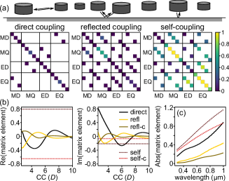
The coupling matrix can be used as a tool for studying the properties of multipole coupling between the particles as well as between the particles and the substrate (Fig. 2a). We distinguish three coupling types which originate from Eq. 11: direct coupling (), substrate-mediated self-coupling () and substrate-mediated interparticle coupling (). Each of the coupling matrix terms can be considered individually to study the contribution of each mechanism into the final result, as presented in Fig. 2. The direct term, which is present even when the particle is embedded in a homogeneous environment, obeys the symmetry dictated by the proposed multipole coupling selection and can be considered an extension of the dipole-dipole coupling term from our previous work [10, 14]. An analysis of this analogy is presented in Appendix C. In contrast to direct coupling, both substrate-mediated coupling terms obey a less-strict selection rule providing a route towards observation of various multipole cross-coupling effects. The only rule except for they obey, is that coupling is not possible between electric and magnetic multipoles when . This rule is discussed in Appendix B.
To elucidate the influence of various parameters on multiple scattering leading to intra-array coupling, we now focus on dipolar terms only, which dominate the optical spectrum of nanodisks in the visible and near-infrared. While electric-electric and magnetic-magnetic dipole coupling is described by the same term, electric-magnetic dipole cross-coupling has its own unique dependence. As shown in our previous work, interparticle coupling depends on array density in an oscillatory manner of a stochastic, quasi-Fabry-Perot cavity [10, 11]. Here, various coupling types exhibit this distinct dependence, cf. Fig. 2b. Self-coupling does not depend on array density. In contrast, substrate-mediated interparticle coupling, similar to direct coupling, also oscillates as a function of density, but its phase is shifted with respect to direct coupling. Focusing on the dipolar case, electric and magnetic dipoles couple in the presence of a layered medium. Interparticle cross-coupling is less pronounced than other coupling types, also across a broad wavelength rage (Fig. 2c), while self-cross-coupling has nearly the same magnitude as self-coupling, but opposite sign (Fig. 2b). The magnitudes of the various dipole matrix elements as function of wavelength for show constant qualitative behavior, as plotted in Fig. 2c. In principle, the direct term is the one which has the biggest impact on the optical properties of a single substrate-supported particle. However, the remaining contributions can be of similar magnitude, especially for arrays of intermediate density with around 4–7.
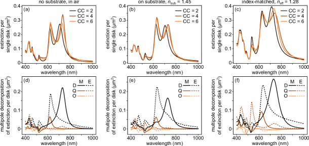
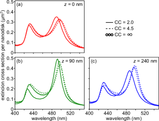
Having presented the intuition that can be obtained by analyzing the properties of the coupling matrix, we study the optical exctinction spectra of substrate-supported amorphous arrays of dielectric nanodisks in the light of the above conclusions. As the first instance we compare the optical response of arrays composed of c-Si [34] cylinders with diameter of 150 nm and height of 225 nm in three environments (see Fig. 3a-c): vacuum, two-layer medium (with refractive index of the substrate equal to 1.45) and an effective homogeneous medium with refractive index of 1.28. Qualitatively, dependence of the extinction spectrum on the minimal center-to-center distance is the same for the vacuum and substrate-supported case. The difference between the two cases is most prominent for CC=4, for which the ratio between the magnetic and electric resonances is substantially different. In contrast, when the disks are placed in an effective medium, the interparticle coupling is strongly modified as a consequence of the ratio between vacuum and medium wavelengths. Since reflection of waves scattered by the substrate is neglected, the phase relations of the scattered and external fields are changes significantly significantly. Consequently, the approximation of substrate-supported case by using an effective permittivity is only poorly applicable to amorphous arrays.
Further differences between the optical properties of arrays embedded in a homogeneous and a layered medium can be observed by performing a multipole decomposition of the extinction spectra shown in Fig. 3d-f. The herein discussed disk supports spectral overlap of multiple electric and magnetic multipoles thanks to the ratio of its dimensions fulfilling . This property thus makes is an excellent candidate for observing magnetoelectric coupling and substrate induced bianisotropy. First of all, the a decomposition shows that there is a significantly larger amplitude of the electric dipole extinction at the magnetic dipole resonance for the substrate-supported case than for both homogeneous cases, as reported previously [19]. Furthermore, our calculations show that in the present case, the presence of the substrate suppresses MD/EQ coupling at the magnetic resonance, which is inherently present in a homogeneous environment. The second significant resonance centered around 600 nm is composed of an electric dipole and a magnetic quadrupole, which is one of the consequences of the fact that the height-to-diameter ratio is larger than unity. Indeed, in contrast to the homogeneous cases, we observe an enhancement of the magnetic dipole around the composite ED/MQ resonance, in contrast to other works which reported even negative MD extinction in vicinity of ED resonance wavelength [19, 21], as well as a significant amplification of the ED resonance itself. In fact, all first four multipoles are coupled, as evidenced by a weak EQ peak around 600 nm. We attribute this observation to substrate-mediated multiple multipole coupling effects, which can be observed, despite that fact that we are using a relatively low-index substrate. Finally, we note that for the index matched case, in addition to the incorrect broadening of the dipolar resonances, this approximation erroneously predicts a sharp EQ around 500 nm.
IV Factors influencing multipole coupling
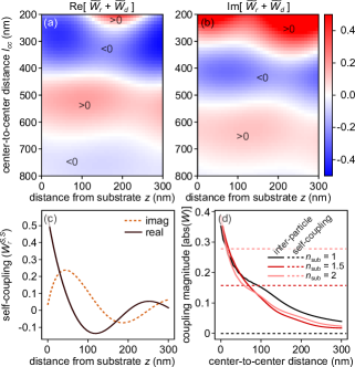
For an amorphous array of nanoparticles embedded in free space, the interparticle coupling depends only on the spatial distribution within the array parametrized by the minimal center-to-center distance. As we have recently shown, this parameter is a useful handle for tuning the optical properties [10]. The presence of the substrate begets additional coupling mechanisms, which are governed by two additional parameters. The obvious one is the substrate refractive index, which modifies the reflection coefficient and hence determines the strength of substrate-mediated coupling and the phase relationship between the field incident onto the substrate and the one reflected off it. Here, we focus on the distance between the array and the substrate, which modifies the phase factors in substrate mediated coupling. Consequently, it changes interparticle coupling (by a phase difference between direct and reflected coupling) and substrate-mediated self-coupling. To analyze this effect, we calculate the total interparticle coupling, as a sum of direct and reflected coupling terms, and the self-coupling between dipoles, in both cases neglecting higher-order terms and magnetoelectric coupling, as a function of distance between the substrate and array and the minimal center-to-center distance. In Fig. 4a-c we present the analysis for nm, which corresponds to the magnetic dipole resonance wavelength for a silicon nanodisk with height 100 nm and diameter 100 nm in free space. One can anticipate that because of the fact that the phase factor depends on the wavenumber in the medium containing the nanoresonators, there is dependence of dipole-dipole coupling on wavelength.
As shown in Fig. 4a-b, modification of the array placement above the substrate, influences the relation between the total interparticle coupling term and the minimal center-to-center distance, especially for dense arrays. For the highest density analyzed (=200 nm), both the amplitude and phase of the coupling term can be tuned within the broad range. At the same time, for dilute arrays, the overall interparticle coupling strength is low and thus cannot be easily modified by changing the phase term via placement of an array. However, even then the optical response of an array substantially depends on the position of an array with respect to the substrate due to the self-coupling term, which changes as a function of the array-substrate distance according to Fig. 4c. A similar modification of the self-coupling term can be observed when the refractive index of the substrate is changed, despite the fact that interparticle coupling is not significantly distinct from the free-space case as shown in Fig. 4d. Notably, the optical response of an array is always determined by the sum of self-coupling and interparticle coupling terms, which makes the array-substrate distance an important parameter for shaping how the interparticle coupling contributes the overall response of an array.
To exemplify this we study the optical spectra of arrays composed of silicon disks (diameter of 100 nm and height of 100 nm, c-Si) placed on or above a substrate with a refractive index of 2. The extinction spectra for selected array-substrate distances and minimal CC distances are presented in Fig. 5. The magnetic dipole resonance is close to 500 nm, which corresponds to coupling terms analyzed in the previous paragraph. Both the amplitude and resonance wavelength are modified by changing the array-substrate distance. This is in line with the coupling matrix study presented in Fig. 4, which illustrates the joint impact of the array density and substrate separation on the optical response. For example, for a dense array with , the magnetic resonance increases in amplitude when going from nm to nm and then diminishes for nm. This is accompanied by corresponding, but inversely proportional width changes and concomitant peak shifts, whose evolution is offset in phase with respect to that of the peak amplitude [8, 14]. The particular behavior of the peak amplitude stems from the fact that the real part of the interparticle coupling term has an opposite sign for nm in comparison with the two other cases. The same conditions cannot be straightforwardly applied to the electric dipole resonance because of the different phase relationship within the coupling matrix between the resonance wavelength and the array–substrate distance. For the properties are close to that of a single particle, yet each array-substrate distance results in a distinct modification of the optical response due to the relation between the coupling matrix and array-substrate distance.
V Refractive index sensing
One of the applications of amorphous arrays of silicon nanodisks is refractometric biosensing based upon the shift of the magnetic dipole resonance wavelength as a result of refractive index modification e.g. due to biomolecule binding [36, 37]. Potential benefits of these Si structures are low losses and high CMOS compatibility, providing a valid alternative for LSPR based sensors. On the other hand, the applicability of dielectric sensors is partially hindered by the fact their sensitivity is generally lower than their plasmonic counterparts [38]. Sensing applications are thus of high relevance and unraveling the role of various effects is important [39]. In recent work, we have observed that if the refractive index change occurs in the bulk of nanoresonator environment, the driving mechanism behind the observed sensitivity is the radiative coupling and that by tuning the spatial distribution of an array and geometry of the sensor one may achieve relatively high sensitivity, which at least partially bridges the gap between plasmonic and dielectric sensing [10]. However, local sensitivity changes are less influenced by array geometry. The main factor enabling good sensitivity of an array of dielectric nanodisks is the interparticle coupling due to an isolated dielectric nanodisk’s low sensitivity in a homogenous environment. Thus, it is important to understand and quantify how a substrate affects its sensing characteristics. The substrate modifies the sensitivity in two ways: via the modification of the Fresnel coefficient as a function of environment’s refractive index and by modifying the phase factor of the reflected plane waves.
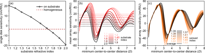
We exemplify this by calculating the bulk refractive index sensitivity within the range for a silicon nanodisk with 160 nm diameter and equal height supported by a substrate with a varying refractive index (see Fig. 6a). For comparison, we also provide the analogous result for a disk in a homogeneous environment. The sensitivity is calculated as the slope of a linear fit to the peak shift. Indeed, the value of substantially affects the sensitivity showing that even for an isolated particle it is a key factor. In principle, for a large contrast between the substrate and the medium the sensitivity is large, while for low contrast the sensitivity can even tend to zero. Moreover, the sign of wavelength shift depends on whether the refractive index of the substrate is higher or lower in comparison with the sensed medium.
When placed in an array, the optical response of the system is additionally modified by the interparticle coupling, which is an important factor determining the refractive index sensitivity of arrays embedded in a homogeneous environment [10]. Next, we calculate the sensitivity of amorphous arrays of Si nanodisks with nm and nm for selected as function of the CC distance, which are plotted in Fig. 6b. The oscillating behavior of the sensitivity mirrors that of the interparticle coupling, which follows a damped, periodic function of . The choice of the minimal center-to-center distance is essential for obtaining high refractive index sensitivity, which oscillates around the corresponding single particle value that is determined by coupling to the substrate, cf. Fig. 6a. Consequently, the choice of substrate determines the sensitivity in the low density limit and then sets the potential range of values attainable by tuning the array density (CC distance). For small the optimal is at the first maximum that occurs at and give approximately 55 nm/RIU (refractive index unit). In contrast for the best sensitivity occurs at and while negative, it gives the global maximum (in the tested range) of 70 nm/RIU.
One consequence of the oscillatory behavior of the minimal center-to-center dependence of the interparticle coupling that has to be accounted for when designing a sensor based on amorphous arrays of dielectric nanoresonators is the nonlinear relation between and the wavelength shift. If changes are small, the sensitivity is linear. However, for larger index changes verification of the linearity may be required. To illustrate this we define the local sensitivity as and study this property for selected s as a function of for a fixed . The results are plotted in Fig. 6c. In general, the observed local sensitivities are close to the average value (plotted also in Fig. 6b). However, for , for which near-field effects have decayed, a substantial spread of the sensitivity values is observed, indicating the nonlinear dependence of the wavelength shift vs the refractive index of the environment. The effect is especially pronounced close to sensitivity minima.
VI Conclusions
In this work we studied the optical properties of substrate-supported amorphous arrays composed of dielectric nanodisks. We proposed a T-matrix based effective model, which accounts for substrate-mediated coupling and thus provides a computationally efficient and accurate way to calculate the response of an array including multiple scattering effects and the presence of the substrate.
An important advantage of using the T-matrix framework is its close relationship with multipole decomposition. We exploit this to provide general multipole coupling rules for both free-space and substrate-supported arrays. We also acknowledge that the proposed framework can be used to study the optical properties up to arbitrarily high multipole orders, which is advantageous with respect to a Green function based approach, where including each new multipole order requires an involved derivation of multipole propagators. Also, to date, multipole studies of substrate-supported arrays were limited to the dipole approximation in a decoupled case in which substrate-mediated coupling is neglected [23]. Here, we show that substrate-mediated coupling is indeed an important factor influencing the optical properties and introduce generalized substrate-induced magnetoelectric coupling beyond magnetic dipole-electric dipole coupling.
The presence of the substrate requires accounting for its influence when designing devices that feature interparticle coupling. This coupling is affected by the additional substrate-mediated coupling term. The other factor determining the optical response of the array, namely the single particle response, is also modified by the substrate-mediated coupling. These additional coupling terms are modified not only by a choice of the substrate material, but also by distance between the array and the substrate. We illustrate both of these effects by using refractometric sensing as a current, relevant example. For dielectric nanoparticle sensors both are especially important, as the mechanism behind the bulk sensitivity is dictated by multiple scattering within the array. In free-space this multiple scattering is confined to direct coupling to other array members. However, the presence of a substrate opens additional coupling channels mediated via reflection, which requires tailoring the substrate refractive index and distance to the array to maximize sensitivity.
We anticipate that this work will be useful for studying optical properties of any photonic system including nanoparticles on a substrate. The proposed T-matrix based effective model can be used as a general and very efficient numerical tool for simulating substrate-supported nanoresonator arrays composed of identical particles with at least an approximate point symmetric spatial distribution. This includes not only amorphous but also periodic arrays, which are often present in metasurfaces. The coupling matrix and multipole decomposition are easily obtained from the model and can shine light onto contributions from interparticle and substrate-mediated coupling effects, which provide further insight into the properties of the coupled nanoparticle array-layered medium system.
Appendix A Vector spherical wave functions
In the T-matrix method the fields are expanded into regular and radiating vector spherical wave functions defined in the spherical coordinate system as
| (20) |
| (21) |
where index 1 corresponds to regular VSWFs and 3 corresponds to radiating VSWFs, are the unit vectors in spherical coordinates, corresponds to the spherical Bessel and spherical Hankel functions of the first kind which correspond to superscripts 1 and 3, respectively, is the associated Legendre polynomial of order and and is a normalization constant equal to
| (22) |
Appendix B Layer-mediated and direct coupling matrices
B.1 Layer-mediated coupling
The layer-mediated coupling matrix is defined as [32]
| (23) |
where is a single index denoting the corresponding VSWF, which otherwise would require three indices with denoting magnetic ( or ) and electric ( or ) multipoles. , are the Sommerfeld integrals meaning that the integral over the angular extent of the array is equal for multipoles of with the same value and zero otherwise.
To show how this matrix is constructed we refer to a formula from [32] in which the Sommerfeld integral theorem is yet to be applied,
| (24) |
where
| (25) |
where is the in-plane wave vector and is the wave vector component perpendicular to the substrate. denotes the layer response matrix constructed according to [30] and corresponds to summation over polarizations. is defined as with all explicit substitued by . For a simple case of a particle above a plane the layer-mediated coupling matrix reads
| (26) |
as the substrate converts downward plane waves into upward reflected ones, the amplitude of which is modified by the Fresnel reflection coefficient .
For the equation
| (27) |
Consequently, if and , then one of the terms of the sum in the integral defining is zero, however, the other one is not, as the product consists of two terms corresponding to the same plane wave polarizations. In contrast, if does not equal , then consists of terms corresponding to the opposite polarizations, one of which always leads to zero and therefore the magnetoelectric coupling can never occur if . The same result can be provided for the direct coupling by analyzing the Wigner-3j symbols in a similar manner to the one provided in the main text.
B.2 Direct coupling
The direct part contains three factors: Bessel functions dependent on the product , Legendre polynomials and and coefficients, which depend on Wigner-3j symbols. Here, we write those coefficients explicitly, because we study the properties of the Wigner-3j symbols in the main text. Due to the presence of the Legendre polynomial, it is convenient to define in spherical coordinates . If
| (28) |
otherwise for
| (29) |
where denotes the Neumann symbol.
Appendix C Relationship between the coupling matrix and the retarded multipole potentials
Previously, we utilized a Green function based approach to calculate the effective multipole moments (polarizabilities) of particles in an amorphous array, denoted as [8, 14, 11, 10]. One can convert the herein presented result from the VSWF basis back to the multipole moments representation using relations between scattering VSWF expansion coefficients and multipole moments from the literature [28, 27]. For magnetic or electric dipoles this relation is expressed as [28]
| (30) |
where is a factor required to obtain correct units and wavelength dependence and is defined as (the difference between [28] and this work stems from CGS units in [10]). This equation is easily rewritten into matrix form,
| (31) |
with being defined as
| (32) |
One can then utilize for basis conversion
| (33) |
Finally, we relate , which is used in [11], to , which is the dipole-dipole part of the coupling matrix used here, by evaluating it with Eq. 33
| (34) |
which, knowing that , reduces to
| (35) |
Acknowledgements.
We acknowledge support from the Polish National Science Center via the projects 2017/25/B/ST3/00744 and 2019/34/E/ST3/00359. Computational resources were provided by the ICM-UW (Grant #G55-6). K.M.C. would like to thank Amos Egel for many fruitful discussions on the T-matrix method and the SMUTHI code.References
- Staude and Schilling [2017] I. Staude and J. Schilling, Metamaterial-Inspired Silicon Nanophotonics, Nat. Photon. 11, 274 (2017).
- Kuznetsov et al. [2012] A. I. Kuznetsov, A. E. Miroshnichenko, Y. H. Fu, J. Zhang, and B. Luk’yanchuk, Magnetic light, Scientific Reports 2, 2045 (2012).
- Liu and Kivshar [2018] W. Liu and Y. S. Kivshar, Generalized Kerker Effects in Nanophotonics and Meta-Optics [Invited], Opt. Express 26, 13085 (2018).
- Decker et al. [2015] M. Decker, I. Staude, M. Falkner, J. Dominguez, D. N. Neshev, I. Brener, T. Pertsch, and Y. S. Kivshar, High-Efficiency Dielectric Huygens’ Surfaces, Adv. Opt. Mater. 3, 813 (2015).
- Zenin et al. [2020] V. A. Zenin, C. E. Garcia-Ortiz, A. B. Evlyukhin, Y. Yang, R. Malureanu, S. M. Novikov, V. Coello, B. N. Chichkov, S. I. Bozhevolnyi, A. V. Lavrinenko, and N. A. Mortensen, Engineering nanoparticles with pure high-order multipole scattering, ACS Photonics 7, 1067 (2020).
- Auguié and Barnes [2008] B. Auguié and W. L. Barnes, Collective resonances in gold nanoparticle arrays, Phys. Rev. Lett. 101, 143902 (2008).
- Babicheva and Moloney [2018] V. E. Babicheva and J. V. Moloney, Lattice Effect Influence on the Electric and Magnetic Dipole Resonance Overlap in a Disk Array, Nanophotonics 7, 1663 (2018).
- Antosiewicz et al. [2012] T. J. Antosiewicz, S. P. Apell, M. Zäch, I. Zorić, and C. Langhammer, Oscillatory optical response of an amorphous two-dimensional array of gold nanoparticles, Physical Review Letters 109, 247401 (2012).
- Antosiewicz and Tarkowski [2015] T. J. Antosiewicz and T. Tarkowski, Localized Surface Plasmon Decay Pathways in Disordered Two-Dimensional Nanoparticle Arrays, ACS Photonics 2, 1732 (2015).
- Czajkowski and Antosiewicz [2020a] K. M. Czajkowski and T. J. Antosiewicz, Electromagnetic Coupling in Optical Devices Based on Random Arrays of Dielectric Nanoresonators, Journal of Physical Chemistry C 124, 896 (2020a).
- Czajkowski and Antosiewicz [2020b] K. Czajkowski and T. Antosiewicz, Effective dipolar polarizability of amorphous arrays of size-dispersed nanoparticles, Optics Letters 45, 3220 (2020b).
- Babicheva and Evlyukhin [2019] V. E. Babicheva and A. B. Evlyukhin, Analytical model of resonant electromagnetic dipole-quadrupole coupling in nanoparticle arrays, Physical Review B 99, 195444 (2019).
- Terekhov et al. [2019] P. D. Terekhov, V. E. Babicheva, K. V. Baryshnikova, A. S. Shalin, A. Karabchevsky, and A. B. Evlyukhin, Multipole analysis of dielectric metasurfaces composed of nonspherical nanoparticles and lattice invisibility effect, Physical Review B 99, 045424 (2019).
- Antosiewicz and Apell [2014] T. J. Antosiewicz and S. P. Apell, Plasmonic glasses: Optical properties of amorphous metal-dielectric composites, Opt. Express 22, 2031 (2014).
- Maimaiti et al. [2020] A. Maimaiti, P. P. Patra, S. Jones, T. J. Antosiewicz, and R. Verre, Low‐Loss Hybrid High‐Index Dielectric Particles on a Mirror for Extreme Light Confinement, Advanced Optical Materials 8, 1901820 (2020).
- Sugimoto and Fujii [2018] H. Sugimoto and M. Fujii, Broadband Dielectric-Metal Hybrid Nanoantenna: Silicon Nanoparticle on a Mirror, ACS Photonics 5, 1986 (2018).
- Butakov and Schuller [2016] N. A. Butakov and J. A. Schuller, Designing Multipolar Resonances in Dielectric Metamaterials, Scientific Reports 6, 1 (2016).
- Chen et al. [2017] Y. Chen, Y. Zhang, and A. Femius Koenderink, General point dipole theory for periodic metasurfaces: magnetoelectric scattering lattices coupled to planar photonic structures, Optics Express 25, 21358 (2017), arXiv:1512.00582 .
- Miroshnichenko et al. [2015] A. E. Miroshnichenko, A. B. Evlyukhin, Y. S. Kivshar, and B. N. Chichkov, Substrate-Induced Resonant Magnetoelectric Effects for Dielectric Nanoparticles, ACS Photonics 2, 1423 (2015).
- Albooyeh et al. [2015] M. Albooyeh, R. Alaee, C. Rockstuhl, and C. Simovski, Revisiting substrate-induced bianisotropy in metasurfaces, Physical Review B - Condensed Matter and Materials Physics 91, 195304 (2015).
- Sinev et al. [2016] I. Sinev, I. Iorsh, A. Bogdanov, D. Permyakov, F. Komissarenko, I. Mukhin, A. Samusev, V. Valuckas, A. I. Kuznetsov, B. S. Luk’yanchuk, A. E. Miroshnichenko, and Y. S. Kivshar, Polarization control over electric and magnetic dipole resonances of dielectric nanoparticles on metallic films, Laser & Photonics Reviews 10, 799 (2016).
- Pors et al. [2015] A. Pors, S. K. H. Andersen, and S. I. Bozhevolnyi, Unidirectional scattering by nanoparticles near substrates: generalized Kerker conditions, Optics Express 23, 28808 (2015).
- Babicheva et al. [2017] V. E. Babicheva, M. I. Petrov, K. V. Baryshnikova, and P. A. Belov, Reflection compensation mediated by electric and magnetic resonances of all-dielectric metasurfaces [Invited], Journal of the Optical Society of America B 34, D18 (2017), arXiv:1511.08473 .
- Nechayev et al. [2019] S. Nechayev, R. Barczyk, U. Mick, and P. Banzer, Substrate-Induced Chirality in an Individual Nanostructure, ACS Photonics 6, 1876 (2019), arXiv:1905.02619 .
- Klös et al. [2019] G. Klös, M. Miola, and D. S. Sutherland, Increased Refractive Index Sensitivity by Circular Dichroism Sensing through Reduced Substrate Effect, Journal of Physical Chemistry C 123, 7347 (2019).
- Garciá-Guirado et al. [2020] J. Garciá-Guirado, M. Svedendahl, J. Puigdollers, and R. Quidant, Enhanced Chiral Sensing with Dielectric Nanoresonators, Nano Letters 10.1021/acs.nanolett.9b04334 (2020).
- Grahn et al. [2012] P. Grahn, A. Shevchenko, and M. Kaivola, Electromagnetic multipole theory for optical nanomaterials, New Journal of Physics 14, 093033 (2012).
- Mühlig et al. [2011] S. Mühlig, C. Menzel, C. Rockstuhl, and F. Lederer, Multipole analysis of meta-atoms, Metamaterials 5, 64 (2011).
- Schmehl et al. [1997] R. Schmehl, B. M. Nebeker, and E. D. Hirleman, Discrete-dipole approximation for scattering by features on surfaces by means of a two-dimensional fast Fourier transform technique, Journal of the Optical Society of America A 14, 3026 (1997).
- Egel and Lemmer [2014] A. Egel and U. Lemmer, Dipole emission in stratified media with multiple spherical scatterers: Enhanced outcoupling from OLEDs, Journal of Quantitative Spectroscopy and Radiative Transfer 148, 165 (2014).
- Doicu et al. [2014] A. Doicu, T. Wriedt, and Y. A. Eremin, Light Scattering by Systems of Particles Null-Field Method with Discrete Sources: Theory and Programs (Springer Berlin, 2014).
- Egel et al. [2016] A. Egel, S. W. Kettlitz, and U. Lemmer, Efficient evaluation of Sommerfeld integrals for the optical simulation of many scattering particles in planarly layered media, Journal of the Optical Society of America A 33, 698 (2016).
- Egel et al. [2017] A. Egel, Y. Eremin, T. Wriedt, D. Theobald, U. Lemmer, and G. Gomard, Extending the applicability of the T-matrix method to light scattering by flat particles on a substrate via truncation of sommerfeld integrals, Journal of Quantitative Spectroscopy and Radiative Transfer 202, 279 (2017).
- Schinke et al. [2015] C. Schinke, P. C. Peest, J. Schmidt, R. Brendel, K. Bothe, M. R. Vogt, I. Kröger, S. Winter, A. Schirmacher, S. Lim, H. T. Nguyen, and D. MacDonald, Uncertainty analysis for the coefficient of band-to-band absorption of crystalline silicon, AIP Advances 5, 67168 (2015).
- Hinrichsen et al. [1986] E. L. Hinrichsen, J. Feder, and T. Jossang, Geometry of Random Sequential Adsorption, J. Stat. Phys. 44, 793 (1986).
- Bontempi et al. [2017] N. Bontempi, K. E. Chong, H. W. Orton, I. Staude, D.-Y. Choi, I. Alessandri, Y. S. Kivshar, and D. N. Neshev, Highly sensitive biosensors based on all-dielectric nanoresonators, Nanoscale 9, 4972 (2017).
- Yavas et al. [2017] O. Yavas, M. Svedendahl, P. Dobosz, V. Sanz, and R. Quidant, On-a-chip biosensing based on all-dielectric nanoresonators, Nano Lett. 17, 4421 (2017).
- Bosio et al. [2019] N. Bosio, H. Šípová-Jungová, N. O. Länk, T. J. Antosiewicz, R. Verre, and M. Käll, Plasmonic versus All-Dielectric Nanoantennas for Refractometric Sensing: A Direct Comparison, ACS Photonics 6, 1556 (2019).
- Yavas et al. [2019] O. Yavas, M. Svedendahl, and R. Quidant, Unravelling the role of electric and magnetic dipoles in biosensing with si nanoresonators, ACS Nano 13, 4582 (2019).