Streaming Erasure Codes over Multi-hop Relay Network
Elad Domanovitz, Ashish Khisti, Wai-Tian Tan, Xiaoqing Zhu, and John Apostolopoulos
E. Domanovitz and A. Khisti are with the Department of Electrical and Computer Engineering, University of Toronto, Toronto, ON M5S 3G4, Canada (email: elad.domanovitz@utoronto.ca, akhisti@ece.utoronto.ca)W.-T. Tan, X. Zhu, and J. Apostolopoulos are with Cisco Systems, San Jose, CA 95134, USA.The material in this paper was presented in part at the 2020 IEEE
International Symposium on Information Theory, Los Angeles, CAL.
Abstract
This paper studies low-latency streaming codes for the multi-hop network. The source is transmitting a sequence of messages (streaming messages) to a destination through a chain of relays where each hop is subject to packet erasures. Every source message has to be recovered perfectly at the destination within a delay constraint of time slots. In any sliding window of time slots, we assume no more than erasures introduced by the ’th hop channel. The capacity in case of a single relay (a three-node network) was derived by Fong [1], et al. While the converse derived for the three-node case can be extended to any number of nodes using a similar technique (analyzing the case where erasures on other links are consecutive), we demonstrate next that the achievable scheme, which suggested a clever symbol-wise decode and forward strategy, can not be straightforwardly extended without a loss in performance. The coding scheme for the three-node network, which was shown to achieve the upper bound, was “state-independent” (i.e., it does not depend on specific erasure pattern). While this is a very desirable property, in this paper, we suggest a “state-dependent” (i.e., a scheme which depends on specific erasure pattern) and show that it achieves the upper bound up to the size of an additional header. Since, as we show, the size of the header does not depend on the field size, the gap between the achievable rate and the upper bound decreases as the field size increases.
I Introduction
Real-time interactive video streaming is an integral part of the day-to-day activity of many people in the world. Traditionally, most of the traffic on the internet is not sensitive to the typical delay induced by the network. However, as networks evolved, more and more people are using the network for real-time conversations, video conferencing, and on-line monitoring. According to [2], IP video traffic will account for 82 percent of traffic by 2022. Further, live video is projected to grow 15-fold to reach 17 percent of Internet video traffic by 2022.
All types of traffic are susceptible to errors, and therefore many applications use an error-correcting mechanism. One fundamental difference between real-time video streaming and other types of traffic is the (much more stringent) latency requirement each packet has to meet in order to provide a good user experience. A very common error-correcting mechanism is automatic repeat request (ARQ). Using ARQ means that the latency (in case of an error) is at least three times the one-way delay, which in many cases may violate the latency requirements for real-time interactive video streaming.
An alternative method for handling errors in the transmission is forward error correction (FEC). Using FEC has the potential to lower the recovery latency since it does not require communication between the receiver and transmitter. However, in many cases, when FEC is designed, the emphasis is on its error-correcting capabilities while ignoring latency constraints. Two commonly used codes are Low-density parity-check (LDPC) [3, 4] and digital fountain codes [5, 6]. The typical block length of these codes is very long (usually a few hundreds of symbols) hence precluding their use for real-time interactive applications.
Low-latency FEC codes are already implemented and have a noticeable impact on the quality of real-time interactive applications. Typically, maximum-distance separable (MDS) codes are used to transmit an extra parity-check packet per every two to five packets [7]. For example, in [8], the FEC implemented in Skype is described, and it is argued that this mechanism is one of the main contributors to the success of this application.
Memory Maximum Distance Separable convolutional codes (m-MDS) discussed in [9, 10, 11] are a class of codes that guarantee decoding assuming the decoder has received sufficiently many parity-check packets. These codes serve as the baseline codes for achieving point-to-point capacity in channels with arbitrary erasures. While in traditional (systematic) m-MDS codes, the parity is appended to the data, in [12], a design of a FEC aimed to reduce the end-to-end average in-order delay (i.e., the time packets spend at the receiver before they can be further processed which was studied in [13]) was described in which a packet composed only from parity symbols is transmitted at a pre-defined rate. While this work considered inserting a single parity packet in each interval, in [14], this concept was extended to allow insertion of multiple packets in each interval, and thus, the benefit of this FEC was extended to highly lossy links.
In another line of work, [15] derived the capacity of low-latency FEC (while denoting it as streaming codes) for a (deterministic) channel with bursts of erasures. This work was followed by a plurality of works [16, 17, 18, 19, 20, 21, 22] which extended the channel model to contain both bursts and arbitrary erasures while analyzing a sliding window model.
While all the works mentioned above-analyzed streaming codes for point-to-point channels, in [1], the performance of streaming codes for the three-node network was analyzed. As a first step, the channel model used in this paper can be denoted as “deterministic arbitrary erasure channel”. In this channel model, the location of erasures can be arbitrary (does not necessarily occur in bursts). However, the number of erasures is (globally) upper bounded. For this model, the capacity of streaming codes was first established. Then, it was shown that the derived results also hold for a sliding window model in which only the number of erasures in any given window is upper bounded (i.e., the limit on the global number of erasures was removed).
When analyzing achievable schemes, in [1], a straightforward extension of point-to-point codes to a setup with a relay was first described. In this extension, each hop uses a point-to-point code, and optimization is carried on the allocation of the delay to be utilized by each code. Denoting this approach as “message-wise” decode and forward strategy (since each message is fully decoded at the relay prior to forwarding it), [1] showed that this scheme is inferior to a more sophisticated scheme denoted as “symbol-wise” decode and forward in which the relay forwards the recovered symbols (before the entire message can be decoded) to the destination. Further, showing that the rate achieved by “symbol-wise” decode and forward coincides with the upper bound resulted in the capacity of the three-node relay network.
Analyzing the capacity of the three-node network shows that when constraints are imposed per segment rather than globally (while meeting the same global requirements), the capacity increases. For example, as we demonstrate next, treating the network as a single-hop link with a maximum of erasures and a total delay constraint of symbols is worse than analyzing a three-node network where a maximum of erasures are expected in the first segment and a maximum of erasures are expected in the second segment with a total delay of symbols. However, internet paths almost never consist of only a single relay (see, e.g., [23, 24]). Hence, designing a streaming code for a path consisting of multiple links when possible (i.e., take into account the error behavior of each link rather than aggregate across all of the links) is expected to result in improved performance guarantees.
The coding scheme described in [1], which was shown to achieve the capacity of the network, has another appealing property, which is “state-independent”, i.e., it does not depend on the specific location of erasures in the different segments. Unfortunately, as we show next, there is no straightforward extension of this scheme to a more general case (a network with more than three nodes). The scheme suggested in this paper for any number of relays is a “state-dependent” scheme, i.e., it is a scheme which reorders the symbols transmitted by each relay based on the erasure patterns that occurred in the previous links. While requiring an additional header to allow each relay to encode the received symbols transmitted to the next relay, we show that it can be easily used for any number of relays.
In this paper, we first extend the upper bound derived in [1] to the general case of a multi-hop relay network. We then describe the state-dependent scheme for the general relay scenario and show it achieves the upper bound up to an additional overhead (a required header). We further show that the size of the header is a function of the required delay and the erasure pattern (hence it does not depend on the field size used by the code). Therefore, the gap from the upper bound decreases as the field size increases.
The rest of this paper is organized as follows. Section I-A outlines the network model of interest. Section I-B presents the formulation of streaming codes and outlines the known results for basic network models. In this Section, the problem is defined as coding over the deterministic erasure model. Section I-C presents the main results of this paper. Section I-D provides a motivating example. In this example, we show that a straightforward extension of the (state-independent) achievable scheme for a single relay results in a loss in the minimum delay that can be achieved (while maintaining the same rate) compared to the state-dependent scheme. Section II contains the proof for the upper bound on the achievable rate for a network that consists of any number of relays. Section III presents the state-dependent symbol-wise decode and forward coding scheme and contains proof on its achievable rate. Section IV provides an upper bound on the error probability when using the state-dependent symbol-wise decode and forward coding scheme when used over a channel with random (i.i.d.) erasures. Section V provides numerical results for different coding schemes used over four-node (two relay) network with random (i.i.d.) erasures. Finally, Section VI provides an extension of the presented results to the sliding window channel.
\psfrag{s}[0.75]{$s=r_{0}$}\psfrag{d}[0.75]{$d=r_{L+1}$}\psfrag{r_1}[1]{$r_{1}$}\psfrag{r_2}[1]{$r_{2}$}\psfrag{r_k}[1]{$r_{L}$}\psfrag{N1}[1]{$N_{1}~{}{\rm Erasures}$}\psfrag{N2}[1]{$N_{2}~{}{\rm Erasures}$}\psfrag{Nk}[1]{$N_{L+1}~{}{\rm Erasures}$}\psfrag{A}[0.75]{${\bf s}_{i}\in\mathbb{F}^{k}$}\psfrag{B}[0.75]{${\bf x}_{i}^{(r_{0})}\in\mathbb{F}^{n_{1}}$}\psfrag{C}[0.75]{${\bf y}_{i}^{(r_{1})}\in\mathbb{F}^{n_{1}}$}\psfrag{D}[0.75]{${\bf x}_{i}^{(r_{1})}\in\mathbb{F}^{n_{2}}$}\psfrag{E}[0.75]{${\bf y}_{i}^{(r_{2})}\in\mathbb{F}^{n_{2}}$}\psfrag{F}[0.75]{${\bf x}_{i}^{(r_{2})}\in\mathbb{F}^{n_{3}}$}\psfrag{G}[0.75]{${\bf y}_{i}^{(r_{L})}\in\mathbb{F}^{n_{L}}$}\psfrag{H}[0.75]{${\bf x}_{i}^{(r_{L})}\in\mathbb{F}^{n_{L+1}}$}\psfrag{I}[0.75]{${\bf y}_{i}^{(r_{L+1})}\in\mathbb{F}^{n_{L+1}}$}\psfrag{J}[0.75]{$\hat{\bf s}_{i-T}\in\mathbb{F}^{k}$}\includegraphics[width=433.62pt]{multiLinkDiag.eps}Figure 1: Symbols generated in the -node relay network at time .
I-ANetwork Model
A source node wants to send a sequence of messages
to a destination node with the help of middle nodes . To ease notation we denote the source node as , and destination node as . Let be a non-negative integer, and be natural numbers.
Each is an element in where is some finite field. In each time slot , the source message is encoded into a length- packet to be transmitted to the first relay through the erasure channel . The relay receives where equals either or the erasure symbol . In the same time slot, relay transmits to relay through the erasure channel . Relay receives where equals either or the erasure symbol . The same process continues (in the same time slot) until relay transmits to the destination through the erasure channel . To simplify the analysis we note that we assume zero propagation delay and zero processing delay for the transmission. Hence, in case no coding is applied () and no erasures occur, . When such assumptions are relaxed, extensions to the results described in the paper can be naturally described (see, e.g. [25]).
We first assume that on the discrete timeline, each channel introduces up to arbitrary erasures respectively. The symbols generated in the -node relay network at time are illustrated in Figure 1.
I-BStandard Definitions and Known Results
Definition 1.
An -streaming code consists of the following:
1.
A sequence of source messages where .
2.
An encoding function for each , where is used by node at time to encode according to
3.
A relaying function for node where , for each , where is used by node at time to construct
4.
A decoding function for each is used by node at time to estimate according to
(1)
Definition 2.
An erasure sequence is a binary sequence denoted by where .
An -erasure sequence is an erasure sequence that satisfies . Alternatively, we denote it as a -deterministic erasure channel. The set of -erasure sequences is denoted by . We further denote deterministic erasure network model as -erasure sequences, each occur on a different channel, where for any , the maximal number of erasures on channel is .
Definition 3.
The mapping of an erasure channel is defined as
(2)
Denoting with an admissible erasure sequence in channel , for any erasure sequence and any -streaming code, the following input-output relations holds for the erasure channel for each :
Definition 4.
An -streaming code is said to be -achievable if the following holds for any -erasure sequence (), for all and all , we have
where
(3)
and for previous nodes
(4)
Definition 5.
The rate of an -streaming code is .
If, for a specific , all and , then the -node relay network with erasures reduces to a point-to-point packet erasure channel. It was previously shown in [16] that the maximum achievable rate of the point-to-point packet erasure channel with arbitrary erasures and delay of symbols denoted by satisfies
(5)
It was further shown that the capacity of the point-to-point channel with arbitrary erasures and delay of could be achieved by diagonally interleaving MDS code.
In [1], a three node relay network was analyzed, and the following theorem was shown.
Fix any . Recalling that the point-to-point capacity satisfies (5), we have
(6)
I-CMain Results
In this paper we first derive an upper bound for the achievable rate in -node relay network.
Theorem 2.
Assume a path with relays. For a target overall delay of , where the maximal number of arbitrary erasures in link is . The achievable rate is upper bounded by
(7)
We then suggest an achievable scheme which achieves the upper bound up to a size of an overhead which is required by the scheme. Denoting
(8)
we show the following Theorem.
Theorem 3.
Assume a link with relays. For a target overall delay of , where the maximal number of arbitrary erasures in link is and . When , The following rate is achievable.
Although the deterministic erasure model is formulated in such a way that link introduces only a finite number of erasures over the discrete timeline, the maximum coding rate remains unchanged for the following sliding window model that can introduce infinite erasures. Every message must be perfectly recovered with delay as long as the numbers of erasures introduced by in link in every sliding window of size T + 1 do not exceed . This is further described in Section VI.
We recall that for any natural numbers and , a systematic maximum-distance separable (MDS) -code is characterized by an parity matrix where any columns of
are independent. It is well known that a systematic MDS -code always exists as long as [26]. To simplify notation, we sometimes denote . We will take all logarithms to base throughout this paper. We denote the ’th element of vector as , or sometime as .
I-DMotivating example
Consider a link with up to arbitrary erasures, where the delay constraint the transmission has to meet is symbols. The capacity of this link according to (5) is . Now, assume that in fact, this link is a three-node network (), where up to erasures occur in link and up to erasures occur in link , where transmission has to be decoded with the same overall delay of symbols. This is depicted in Figure 2. The capacity of this link according to (6) is , which is better than the point-to-point link.
We start by recalling the coding scheme that was shown in [1] to achieve capacity. The example we show next is the same as provided in [1] for the scenario described above (in which the total delay and the maximal number of erasures in each channel is ).
Suppose node transmits two bits and at each discrete time to node with delay 3. For each time , node transmits the three-symbol packet according to Table I where for any by convention, and the symbols highlighted in the same color are generated by the same block code.
Since channel introduces at most erasure, each and each can be perfectly recovered by node by time and time respectively. Therefore, at each time , node should have recovered and perfectly with delays 2 and 1 respectively, and it will re-encode them into another three-symbol packet . This is depicted in Table I. Since , and are transmitted by node at time , and respectively, it follows from the fact that node can recover and by time . Consequently, this symbol-wise DF strategy achieves a rate of 2/3.
Time
\lfbox[border-style=solid,border-color=black]
\lfbox[border-style=dashed,border-color=black]
\lfbox[border-style=dotted,border-color=black]
\lfbox[border-style=solid,border-color=black]
\lfbox[border-style=dashed,border-color=black]
\lfbox[border-style=dotted,border-color=black]
\lfbox[border-style=solid,border-color=black]
\lfbox[border-style=dashed,border-color=black]
\lfbox[border-style=dotted,border-color=black]
(a)Symbols transmitted by the source node .
Time
\lfbox[border-style=solid,border-color=black]
\lfbox[border-style=dashed,border-color=black]
\lfbox[border-style=dotted,border-color=black]
\lfbox[border-style=solid,border-color=black]
\lfbox[border-style=dashed,border-color=black]
\lfbox[border-style=dotted,border-color=black]
\lfbox[border-style=solid,border-color=black]
\lfbox[border-style=dashed,border-color=black]
\lfbox[border-style=dotted,border-color=black]
(b)Symbols transmitted by relay node .
Time
\lfbox[border-style=solid,border-color=black]
\lfbox[border-style=dashed,border-color=black]
\lfbox[border-style=dotted,border-color=black]
\lfbox[border-style=solid,border-color=black]
\lfbox[border-style=dashed,border-color=black]
\lfbox[border-style=dotted,border-color=black]
(c)Estimates constructed by the destination node .
TABLE I: A state-less symbol-wise DF strategy for a single relay. Symbols belong to the same code used by the source () and symbols belong to the same code used by the relay () are marked with a frame with the same style.
An important feature of this code is the fact that it is a state-less code, i.e., the structure of the code does not depend on the specific erasure pattern at any of the segments. However, if another relay is to be considered (i.e., the destination is now replaced with relay ), assuming up to erasures in link , the minimal delay required to support rate is . The network of interest is depicted in Figure 3.
TABLE II: Symbols transmitted by node when trying to extend the state-less symbol-wise DF strategy. Symbols belong to the same code are denoted with frame with the same style.
This can be seen since basically using the coding scheme in Table I, relay can be viewed as source with delay of packets (essentially, the delay of different symbols is “reset”). Due to causality, relay can only use the coding scheme of the sender, depicted in Table II. It can be viewed that when , symbol is guaranteed to be recovered only at time .
In this paper, we suggest a state-dependent scheme, i.e., a scheme in which the order of symbols in each block code used (and thus the order in each diagonal) is set according to the erasure pattern in the previous link. The order of the symbols is transmitted to the receiver to allow decoding. Hence, additional overhead is required. We first show an example of the suggested scheme to the three-node network and then show how to extend it to a four-node network.
In the proposed scheme, the source uses the same code suggested in [1], i.e., a MDS code that can recover any arbitrary single erasure in a delay of two symbols combined with diagonal interleaving (i.e., the code is applied on the diagonals). For each time , node transmits the three-symbol packet (symbols belong to the same block code are marked with the same color).
Time
Header
123
123
123
123
123
TABLE III: Transmission of the Source in channel . Symbols belong to the same code are marked with the same color.
When there are no erasures, relay uses the same code as the source while delaying it by one symbol, i.e. relay sends the following three-symbol packet .
If an erasure occurred, the relay would send any available symbols (per diagonal) in the received order until it can decode the information symbols from this block code. Then, the erased symbols will be sent. For example, assuming that a symbol at time is erased in link , relay will send and as depicted in Table IV below. Again, symbols belong to the same block code are marked with the same color. Further, headers which are different than the ones used by are marked with a frame.
Time
Header
123
123
223
123
123
TABLE IV: Transmission of relay in channel , given that symbol was erased when transmitted in link . Symbols belong to the same code are marked with the same color.
We note that the erasure in time in link caused a change in the order of the symbols in packets and . Denoting the order of symbols sent from in each code (alternatively on each diagonal) as , in this example, the header of each packet is composed of the location of the symbols from each block code (the order of the symbols in each diagonal) as they would appear in the code used by .
We show next that the code used by each relay on each diagonal can be viewed as a punctured code of a code that is used by the “bottleneck” relay. i.e., the relay with the smallest rate. Hence, we note that it can be viewed as if the suggested coding scheme only changes the order of symbols per diagonal (taken from the code with the lowest rate), and it does not add or remove symbols. Therefore, using a single index per symbol suffices to allow recovery at each destination.
In our example, as can bee seen in Table IV, at time relay sends with header indicating that the first symbol is the first symbol (marked with underline) in the code , the second symbol is the second symbol in the code and the third symbol is the code .
However, following the erasure occurred at link at time , relay can not send symbol at time as planned (as if there was no erasure). However, it can send which was not erased. With respect to the second symbol, we note that since and were received, can be recovered and used. Similarly, since and were received, symbol can be generated and used. Thus, at time the relay can send . To indicate the change in order of the symbols used in the first code, the header is changed to which should be indicating that the first symbol is the second symbol in the code associated with this diagonal.
At time , the relay can recover and send . Hence, it sends with header indicating now that the second symbol is the first symbol in the code associated with this diagonal. It can be easily verified that the destination can recover the original data at a delay of (assuming any single arbitrary erasure in the link between the relay and destination).
This concept can be applied to additional relays if they exist. For example consider four-node network (). The transmission scheme on the next relay (in this specific example), is the same as the transmission scheme of the first relay, i.e., in case there is no erasure, transmit (on each diagonal) the symbols in the same order as received, delayed by one symbol (i.e., a total delay of two symbols from the sender). If an erasure occurred before decoded the information symbols, transmit the available symbols (again, it is guaranteed that there will be enough symbols). When the information symbols can be decoded, transmit the erased symbols.
For example, in case the symbol transmitted from relay to at time is erased, the suggested transmission scheme of relay is given in Table V below. Again, symbols belong to the same block code are marked with the same color. Further, headers that are different than the ones used by the relay are marked with a frame.
Time
Header
123
123
123
223
213
113
TABLE V: Transmission of relay in channel , given that symbol was erased when transmitted in link . Symbols belong to the same code are marked with the same color.
We note that the erasure in time in link caused a change in order of the symbols in packets and (the order of symbols in time is not the original order, yet it is the same as was transmitted from at time ).
Since the same code is used (with a different order of symbols which is communicated to the receiver), it can be easily verified that each packet can be recovered up to delay of symbols for any arbitrary erasure in the link between the relay and the destination.
In this example, the maximal size of the header is three numbers, each taken from . Hence, its maximal size of the header is bits. Since the block code used in each link transmits two bits using three bits in every channel use, we conclude that the scheme achieves a rate of
(10)
We show next that this idea can be extended to transmitting symbols taken from any field thus in general, the achievable rate when and is
(11)
which approaches as the field size increases. As we further show next, the upper bound for this scenario is indeed .
II Proof of the upper bound
Fix any . Suppose we are given an -achievable -streaming code for some and . Our goal is to show that
(12)
To this end, we let be i.i.d. random variables where is uniform on . Since the -streaming code is -achievable, it follows from Definition 4 that
(13)
for any and any . Consider the two cases.
Case :
Let be the error sequence on link where such that
(14)
We note that (14) means that is the first packet which can be used to recover at . Further, is the first packet which can be used to recover at . Continuing the transmission across all other relays, it follows that is the first packet which can be used to recover . Since it follows the delay constraint can not be met.
Combining (13), (15) and the assumption that , we obtain Since consists of uniform random variables in , the only possible value of is zero, which implies
(16)
Case :
The proof follows the footsteps of [1]. We start by generalizing the arguments given in [1] for the first and second segments to the first and last segments in our case. Then we show how similar techniques can be used to derive a constraint on the code to be used in an intermediate segment.
First Segment (link ):
First we note that for every , message has to be perfectly recovered by node by time given that have been correctly decoded by node , or otherwise a length burst erasure from time to introduced on channel followed by a length burst erasure from time to introduced on channel and so on until a length burst erasure from time to would result in a decoding failure for node , node and all the nodes up to the destination .
Recalling that it then follows that
(17)
for any and non-negative integers denoted by . We note that the following holds (by assuming, for example, the last symbols in every window of symbols starting time are erased):
(18)
Using the chain rule we have the following for each
(19)
Alternatively we note that for all ,
(20)
Hence, (19) also follows from (17), (20) and the chain rule.
Therefore, following the arguments in [1] which we recall here and in Appendix A, we note that the (19) involves source messages and source packets. Therefore, the -achievable -streaming code restricted to channel can be viewed as a point-to-point streaming code with rate and delay which can correct any erasures. In particular the point-to-point code can correct the periodic erasure sequence depicted in Figure 4, which is formally defined as
(21)
\psfrag{d1}[1]{$\ldots$}\psfrag{a}[1]{$T-N_{1}^{L+1}+1$}\psfrag{b}[1]{$N_{1}$}\includegraphics[width=216.81pt]{Periodic1.eps}Figure 4: A periodic erasure sequence with period .
By standard arguments which are rigorously elaborated in Appendix A, we conclude that
(22)
Last Segment (link ):
In addition, for every , message has to be perfectly recovered from
(23)
by node given that have been correctly decoded by node , or otherwise a length burst erasure from time to induced on channel followed by a length burst erasure from time to induced on channel and so on until a length burst erasure from time to induced on channel would result in a decoding failure for node .
It follows that
(24)
for any and non-negative integers denoted by . We note that for all ,
Therefore, following the arguments in [1] which we recall here and in Appendix A, we note that the (26) involves source messages and source packets. Therefore, the -achievable -streaming code restricted to channel can be viewed as a point-to-point streaming code with rate and delay which can correct any erasures. In particular the point-to-point can correct the periodic erasure sequence depicted in Figure 5, which is formally defined as
(27)
\psfrag{d1}[1]{$\ldots$}\psfrag{a}[1]{$T-N_{1}^{L+1}+1$}\psfrag{b}[1]{$N_{L+1}$}\includegraphics[width=216.81pt]{Periodic1.eps}Figure 5: A periodic erasure sequence with period .
By standard arguments which are rigorously elaborated in Appendix A, we conclude that
(28)
The ’th Segment (link ):
Now, when considering a ’th segment (the channel ), we show again that any achievable code restricted to the channel can be viewed as a point-to-point code which should handle any erasures with a delay which we define next.
Combining the arguments given above we note that first, for every , message has to be perfectly recovered by node by time given that have been correctly decoded by node , or otherwise a length burst from time to introduced on channel , followed by a length burst from time to introduced on channel and so on, up to a length burst from time to introduced on channel would result in a decoding failure for node and all the nodes up to the destination .
Further, in addition, for every , message has to be perfectly recovered from
(29)
by node given that have been correctly decoded by node , or otherwise a length burst erasure from time to induced on channel followed by a length burst erasure from time to induced on channel and so on (up to a burst erasure from time to induced on channel ) would result in a decoding failure for node . These constraints are depicted in Figure 7.
Recalling that , and it follows that
(30)
for any and non-negative integers denoted by . We note that for all ,
Therefore, following the arguments in [1] which we recall here and in Appendix A, we note that the (32) involves source messages and source packets. Therefore, the -achievable -streaming code restricted to channel can be viewed as a point-to-point streaming code with rate and delay which can correct any erasures. In particular the point-to-point can correct the periodic erasure sequence depicted in Figure 6, which is formally defined as
(33)
\psfrag{d1}[1]{$\ldots$}\psfrag{a}[1]{$T-N_{1}^{L+1}+1$}\psfrag{b}[1]{$N_{j}$}\includegraphics[width=216.81pt]{Periodic1.eps}Figure 6: A periodic erasure sequence with period .
By standard arguments which are rigorously elaborated in Appendix A, we conclude that
(34)
Therefore we have
(35)
\psfrag{d1}[1.5]{$\ldots$}\psfrag{x}[1]{${\rm x}$}\psfrag{b1}[1]{$\underbrace{~{}~{}~{}~{}~{}~{}~{}~{}~{}~{}~{}}_{N_{1}}$}\psfrag{b2}[1]{$\underbrace{~{}~{}~{}~{}~{}~{}~{}~{}~{}~{}~{}}_{N_{j-1}}$}\psfrag{b3}[1]{$\underbrace{~{}~{}~{}~{}~{}~{}~{}~{}~{}~{}~{}}_{N_{j+1}}$}\psfrag{b4}[1]{$\underbrace{~{}~{}~{}~{}~{}~{}~{}~{}~{}~{}~{}~{}~{}~{}}_{N_{L+1}}$}\psfrag{c}[1.5]{$\ddots$}\psfrag{a1}[1]{\framebox{$i$}}\psfrag{a2}[1]{\framebox{$i+N_{1}-1$}}\psfrag{a3}[1]{\framebox{$i+N_{1}^{j-2}$}}\psfrag{a4}[1]{\fcolorbox{black}{gray!15}{$i+N_{1}^{j-1}-1$}}\psfrag{a5}[1]{\framebox{$i+N_{1}^{j-1}$}}\psfrag{a10}[1]{\framebox{$i+T$}}\psfrag{a9}[1]{\framebox{$i+T-N_{L+1}+1$}}\psfrag{a8}[1]{\framebox{$i+T-N_{j+2}^{L+1}$}}\psfrag{a7}[1]{\fcolorbox{black}{gray!15}{$i+T-N_{j+1}^{L+1}+1$}}\psfrag{a6}[1]{\framebox{$i+T-N_{j+1}^{L+1}$}}\psfrag{r1}[1]{$\rm{Link~{}}(r_{0},r_{1})$}\psfrag{r2}[1]{$\rm{Link~{}}(r_{j-2},r_{j-1})$}\psfrag{r3}[1]{$\rm{Link~{}}(r_{j-1},r_{j})$}\psfrag{r4}[1]{$\rm{Link~{}}(r_{j},r_{j+1})$}\psfrag{r5}[1]{$\rm{Link~{}}(r_{L},r_{L+1})$}\includegraphics[width=433.62pt]{segmentJ.eps}Figure 7: Constrains imposed on transmission in link .
III State-dependent symbol-wise DF
As mentioned above, the achievable scheme we analyze is a state-dependent symbol-wise DF scheme. This scheme is composed from a block code combined with diagonal interleaving. We start with some basic definitions of point-to-point block codes which would be the basis for this scheme.
Definition 6.
A point-to-point -block code consists of the following
1.
A sequence of symbols where .
2.
A generator matrix . The source codeword is generated according to
(36)
3.
A decoding function for each , where is used by the destination at time to estimate according to
(37)
Definition 7.
A point-to-point -block code is said to be -achievable if the following holds for any
-erasure sequence : For the -block code, we have
(38)
for all and and all , where
(39)
with being the symbol-wise erasure function defined in (3).
Recalling from Section II that the rate in channel is upper bounded by where
(40)
Denoting
(41)
The suggested coding scheme is composed of -block codes combined with diagonal interleaving. Each relay is using codes, each one is an -block code that depends on the erasure pattern in the previous relay, i.e., each code can be different.
More formally, let be the ’th symbol of the source message and let be the ’th symbol of the output of encoding function . We may say for each , a single transmission function of relay constructs
(42)
where we show next that is a generator matrix of a MDS code. We assume that for any , .
Denoting with
(43)
an example of the diagonal interleaving of a single code is given in Table VI below.
Time
TABLE VI: An example of a single code transmitted in
Therefore, each transmitted packet at relay is composed of symbols, each of which is taken from a different code. Recalling that means that we take the ’th element from the vector resulting from multiplying with the generator matrix , an example of a packet sent by relay is given in (44) below.
(44)
We note again that the specific structure of each is defined according to the erasure pattern of the previous links.
We describe next the process of generating (required to transmit in each one of the relays).
•
At the sender (), use an MDS code. Hence, is the generator matrix of an MDS code.
•
Each encoder at relay () performs the following
1.
Store any non-erased symbols from the first received symbols from link , i.e., all non-erased symbols from
(45)
2.
Start transmitting at time (while continuing to store the received symbols from link ). Until time , forward the symbols received from link by the order they were received, i.e., forward the non-erased symbols from
(46)
Noting the means that relay forwards the symbols received by the order they were received, i.e., all non-erased symbols from
(47)
3.
At time , recover . In Lemma 1 below we prove that it is feasible for any -erasure sequence.
4.
Transmit until time encoded symbols. The encoded symbols should be non-received symbols from MDS code to be defined below.
5.
For each transmitted symbol, attach a header which will be defined next.
Recalling the definition of (8), the following Proposition sheds light on the suggested method of encoding once it is recovered at (step (4)) in order to guarantee that each is a generator matrix of MDS code and further simplify the header required to allow decoding.
Proposition 1.
All block codes used by nodes where to transmit can be generated by puncturing and applying a permutation to the MDS code which is associated with rate .
This proposition holds since (the number of information symbols) is the same for all codes. Denoting , we recall that the MDS code which is the MDS code associated with rate can correct any . Puncturing any columns from the generator matrix of this code results with a code that can correct any erasures.
In fact, denoting with the generator matrix of MDS code, can be viewed as taking columns from and apply permutation on the order of the columns. The specific columns taken from and their order is defined by the specific erasure pattern which occurs.
Further, following Proposition 1 we define the header as a number which indicates the location of the column from that was used to generate this symbol. Thus, the header attached to each symbol transmitted from each relay is a number in the range .
Thus we have the following Lemma.
Lemma 1.
For any -erasure sequence, any and any , is a generator matrix of MDS code.
Proof.
From the construction, is an MDS code. Hence we assume by induction that is an MDS code and show that is an MDS code.
We note that the only non-trivial steps in generating are steps (2) and (3). Assuming -erasure sequence means that for any
(48)
i.e., that the maximal number of erasures in line is . Since we assumed is an MDS code it follows that it is guaranteed that symbols out of the transmitted symbols will not be erased. Further, since relay starts sending the coded symbols at time and relay starts forwarding the non-erased symbols received from at time (after buffering any non erased symbols from the first coded symbols) it is guaranteed that relay could forward the non-erased coded symbols sent from .
In step (3), relay needs to recover all information symbols at time . We note that this step is feasible since, assuming is the generator matrix of an MDS code, any of its information symbols can be recovered from any non-erased symbols. We note that relay transmits its code in time indices
(49)
therefore, the last symbol of this code is received at relay at index
\psfrag{d1}[1.5]{$\ldots$}\psfrag{b1}[1]{$n_{j+1}$}\psfrag{b2}[1]{$n_{j}$}\psfrag{b3}[1]{$n_{j}-N_{j}=k$}\psfrag{a1}[1]{\framebox{$i+N_{1}^{j}$}}\psfrag{a2}[1]{\framebox{$i+N_{1}^{j-1}+n_{j}=i+N_{1}^{j}+k$}}\psfrag{a3}[1]{\framebox{$i+N_{1}^{j-1}$}}\psfrag{a4}[1]{\framebox{$i+N_{1}^{j}+n_{j+1}$}}\psfrag{c1}[1]{$(r_{j-1},r_{j})$}\psfrag{c2}[1]{$(r_{j},r_{j+1})$}\includegraphics[width=216.81pt]{transScheme_kminus1_1.eps}Figure 8: Two regions of transmission in link . The symbols with white background are symbols forwarded from link . The shaded symbols are transmitted after the information symbols are decoded hence they are either symbols erased in link or additional (independent) linear combinations of the information symbols.
Since we assumed is an MDS code, it follows its information symbols can be recovered from any symbols received. However, in order to recover the information symbols, relay needs to know the structure of . Using the header attached to each received symbol relay it is guaranteed that relay could recover (all ) information symbols at time .
Further, since after the recovery of the symbols, adds unique columns from the process described above results with which is the generator matrix of MDS code which can recover any erasures.
∎
For specific examples on the modification of the block codes as a function of rate change between links, see Appendix B.
Suppose , and let and . For any such that , there exists an -achievable point-to-point -block code.
Proof.
The proof follows directly from the definitions of MDS code. Any MDS code is block code. Thus, any MDS code is -achievable where all symbols can be decoded by the end of the code block.
∎
Recalling that when transmitting , relay starts its transmission at time we have the following corollary.
Corollary 1.
Recalling that relay (for any ) starts transmitting the coded symbols of at time , it follows that for any -erasure sequence the code used in each relay to transmit is -achievable point-to-point block code, i.e., all the symbols of can be decoded at relay by delay of
(51)
We take a closer look at the channel between the last relay and the destination . Following Corollary 1 we have
Corollary 2.
For any , and for any -erasure sequence, can be decoded at the destination at time
(52)
at the destination, i.e., using the construction suggested above, can be decoded at the destination with delay of for any .
Next, we show that this Corollary means that the construction suggested above generates a streaming code which is also -achievable.
Lemma 3.
The streaming code resulting from using defined above in each relay for every is a streaming code which is also -achievable.
Proof.
Our goal is to show that the destination () can recover based on
(53)
Following Lemma 1 it follows each is MDS code. From Corollary 2 it follows that for any , (which is the first element in ) can be recovered with a delay of for any -erasure sequence. Similarly we note that can be recovered with a delay of and can be recovered with delay of . Thus, we conclude that the streaming code resulting from the construction described above is a streaming code which is also -achievable.
∎
Thus to prove Theorem 3, we need to show that when , can be generated at each relay for and analyze the overall rate (by bounding the rate of the additional header).
We first note that, as mentioned in Section I-A, an MDS code exists as long as . Therefore, following Lemma 1, when it follows that for any -erasure sequence, any and any , there exists which is a generator matrix of MDS code.
Following Lemma 3 it follows that streaming code resulting from using defined above in each relay for every is a streaming code which is also -achievable. The rate in relay , without taking the size of the header into account, is . Thus, from Definition 5, the overall rate of transmission is upper bounded by
(54)
The header attached to each packet sent from relay is composed from stacking the headers used by each symbol generated from a block code which is part of each transmission packet. As we defined above, this header is a number from . Hence the size of the header is bits. We further note that the size of the header is upper bounded by .
To conclude, each node transmits coded symbols (each taken from field ) along with bits of header to transfer information symbols (each taken from field ). The overall rate is
IV An upper bound on loss probability attained by state-dependent symbol-wise DF for random erasure
In Section III, the state-dependent symbol-wise DF scheme was described, and a lower bound on its achievable rate was derived while assuming a deterministic erasure model. In this section, we develop an upper bound on the average loss probability when this scheme is applied over channels with random (i.i.d.) erasures.
Let be the k source symbols transmitted by node at each discrete time . We note that for the , MDS codes used by the sender, the following property holds:
•
For every located at the ()th position of the length- packet transmitted at time by the streaming code over , is generated by the relay, at the latest, at time (i.e., after transmission of symbols from ). If there are at most erasures inside the window , then .
Hence, can be fully recovered at relay if for all , in any window , there are at most erasures. We bound the loss probability by analyzing the probability in which in the window there are at most erasures.
Since the state-dependent symbol-wise DF encode the same information symbols (per diagonal) in each relay, we note that in the general case, when transmitting the streaming code over :
•
is generated by the relay, at the latest, at time (i.e., after transmission of symbols from relay ). If there are at most erasures inside the window , .
Hence, can be fully recovered at relay if for all , in any window there are at most erasures. Similar to [1], we bound the loss probability by analyzing the probability in which in the window there are at most erasures.
Denoting the average Loss probability as
(56)
achieved by the above state-dependent symbol-wise DF strategy under the random erasure model. Define to be the erasure probability in link . According to the achievability conditions we have
(57)
for every . Since
(58)
It follows that
(59)
where does not depend on (or on any other for any ). Hence, decays exponentially fast in .
V Numerical results
In this section, we show the performance of the state-dependent symbol-wise DF scheme on a random model. We consider a statistical -node relay network where i.i.d. erasures are independently introduced to all channels. We denote with the probability of experiencing an erasure in each time slot for channel .
Similar to [1], we will compare state-dependent symbol-wise DF with message-wise DF and instantaneous forwarding, which we briefly recall. In message-wise DF, all the symbols in the same source message are decoded by relay subject to the delay constraint such that . The overall rate of message-wise DF is
(60)
More precisely, we consider message-wise DF scheme constructed by concatenating streaming codes where the ’th code is a -streaming code.
We also consider an instantaneous forwarding (IF) strategy, which uses a point-to-point streaming code over the -node relay network as if the network is a point-to-point channel. More specifically, under the IF strategy, the source transmits symbols generated by the streaming code and relay
forwards every symbol received from relay in each time slot. The overall point-to-point channel induced by the IF strategy experiences an erasure if either one of the channels experiences an erasure. This results with rate
(61)
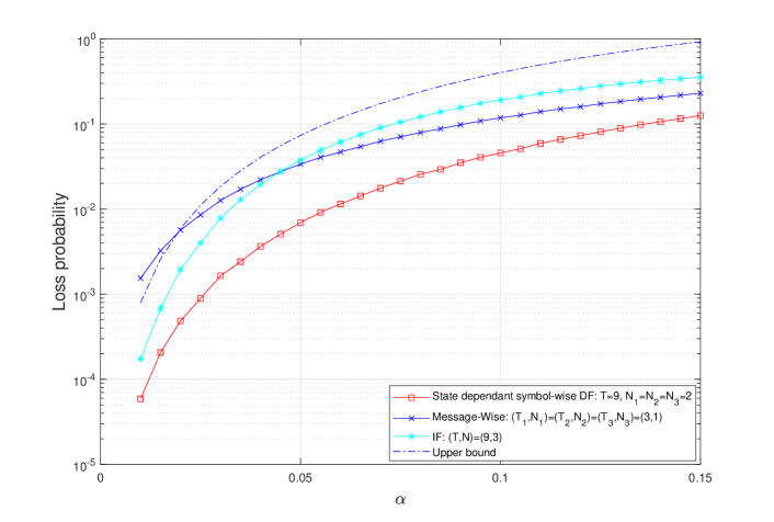
We first study the error-correcting capabilities of all schemes in case of having two relays with a rate equal to 2/3 and maximal total delay of . We further simulate a symmetric topology, i.e., we assume the same error probability for all segments. Since we assume symmetric topology, we focus on schemes that have the same error-correcting capabilities for all segments.
•
State-dependent symbol-wise DF can support erasures in each segment which is constructed using concatenating three streaming code. While the rate of the code is strictly lower than due to the overhead it uses, as we noted above, it approaches as increases.
•
Message-wise DF can support erasures in each segment which is constructed using concatenating three streaming code. As mentioned in [18], higher rate codes (such as ) are excluded since can correct more erasure patterns.
•
For IF, we note that since and we require we get . Hence IF uses a streaming code.
In Figure 9 we plot the frame loss ratio for state-dependent symbol-wise DF, Message-wise DF and for IF. We further plot the upper bound for State-dependent symbol-wise DF derived in Section IV with , and while assuming .
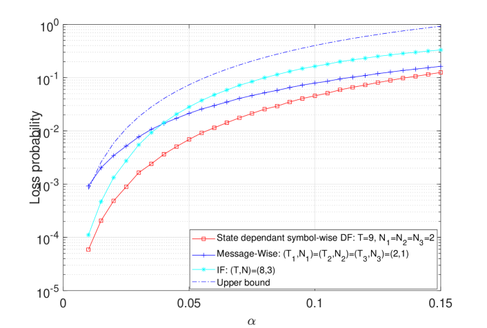
Since enforcing rate resulted with low overall delay ( for example in case of message-wise DF), we further plot the performance of all schemes where we force and allow the rate to be greater than or equal to (while trying to find the smaller rate possible). Figure 10 depicts all schemes when the rates are as close as possible to (from above) with . We note that, again, state-dependent symbol-wise DF outperforms all other methods.
Figure 9: Four-node (two relays) network loss probability for state-dependent symbol-wise DF, message-wise DF and IF with , rate and largest where denotes the erasure probability (same over all hops).Figure 10: Four-node (two relays) network loss probability for state-dependent symbol-wise DF, message-wise DF and IF with delay , and largest where denotes the erasure probability (same over all hops).
VI Extension to Sliding Window Model
Consider the following sliding window model. For each , channel introduces at most erasures in any period of consecutive time slots (sliding window of size ).
Under the sliding window described above, denote with as the upper bound on the achievable rate for channel. We further denote as the achievable rate under the sliding window model.
Our goal is to show that
(62)
and
(63)
With respect to the upper bound, since for any , -erasure sequence can be introduced by channel in the sliding window model (62) holds.
Next, we show that the state-dependent scheme can achieve the same rate under the sliding window model. As was shown in Section III, for any , each symbol can be recovered as long as channel introduces at most erasures in a window of size . From (34) we have , it follows that all conditions hold under the sliding window model thus the state-dependent code can recover all symbols and hence (63) holds.
VII Concluding Remarks
Streaming codes became an integral part of real-time interactive video streaming applications. The ability to improve the quality of user-experience while meeting stringent latency constraints helped to transform these applications from a niche to one of the fastest-growing segments of IP traffic.
The problem of quantifying the capacity of streaming codes was first addressed for point-to-point links. Later it was extended for three-node networks and in this work, we extended the upper bound of streaming codes to multi-hop relay networks (i.e., for networks with any number of nodes) and further, we suggested an achievable scheme which achieves this upper bound with a gap that vanishes as the field size used gets larger. While for three-node networks, capacity can be achieved with “state-independent” symbol-wise DF coding scheme, we showed that this scheme could not be easily extended to more than three-nodes and suggested a symbol-wise DF “state-dependent” coding scheme.
While starting by describing the upper bound and proving the achievable scheme over “deterministic arbitrary erasure channel”, Section VI outlined that these results also hold for a sliding window model. While this model is a simplified model for a random erasure model, Section IV showed that the error probability of the achievable scheme could be upper bounded for random channel and Section V provided numerical results showing that the proposed coding scheme outperforms other simple options such as message-wise DF and instantaneous forwarding.
Packet erasures can occur either in sparse patterns or in a bursty manner. The first works on streaming codes analyzed the case of burst erasure channel. Later, works studied channels which could have either a burst or sparse erasures in a given window. Future work may explore streaming codes in a setup with relays in this case. Another avenue is to study streaming codes for more complicated networks.
Appendix A Derivations In The Converse Proof Of Theorem2
Deviation of (22): Since the -achievable -streaming code restricted to channel can be viewed as a point-to-point streaming code with rate and delay which can correct the periodic erasure sequence illustrated in Figure 4, it follows from the arguments in [17] Section IV-A that (22) holds. For the sake of completeness, we present a rigorous proof below.
because source messages can take values and source packets can take at most values for each . Taking logarithm on both sides of (64) followed by dividing both sides by , we have
(65)
Since (65) holds for all , it follows that (22) hold.
Deviation of (28): Since the -achievable -streaming code restricted to channel can be viewed as a point-to-point streaming code with rate and delay which can correct the periodic erasure sequence illustrated in Figure 5, it follows from the arguments in [17] Section IV-A that (28) holds. For the sake of completeness, we present a rigorous proof below.
because source messages can take values and source packets can take at most values for each . Taking logarithm on both sides of (66) followed by dividing both sides by , we have
(67)
Since (67) holds for all , it follows that (28) hold.
Deviation of (32): Since the -achievable -streaming code restricted to channel can be viewed as a point-to-point streaming code with rate and delay which can correct the periodic erasure sequence illustrated in Figure 6, it follows from the arguments in [17] Section IV-A that (34) holds. For the sake of completeness, we present a rigorous proof below.
because source messages can take values and source packets can take at most values for each . Taking logarithm on both sides of (66) followed by dividing both sides by , we have
(69)
Since (69) holds for all , it follows that (28) hold.
Appendix B Examples for rate change in relay
As mentioned above, relay may need to increase or decrease the rate of the code used by relay . Below, we show examples for the following two cases:
•
. This means that , i.e., that the block size of the MDS code used by relay is smaller than the block size used by relay . At time , node can recover the original data and send any of the erased symbols of the code used by .
An example is given in Table VII for (where ).
We note that in this example .
Relay forwards the first symbols it receives. At the relay can recover the original data, hence from this point it sends (for example) the erased symbols.
Link
Link
TABLE VII: Example of increasing the rate between links. In this example, , hence . Assuming symbol and were erased when transmitted in link . Parity symbol are shaded.
•
. This means that , i.e., the block size of the code used by relay is larger than the block size used by relay .
At time , relay can again recover the original data and hence transmit additional symbols needed to allow handling any erasures in the link .
An example is given in Table VIII for (where, again, ).
Relay forwards the first symbols it receives. At , the relay can recover the original data, hence from this point is sends (for example) the erased symbols while adding parity symbols to reach the required rate.
Link
Link
TABLE VIII: Example of reducing rate between nodes. In this example, , hence . Assuming symbol was erased when transmitted in link .Parity symbols are shaded.
References
[1]
S. L. Fong, A. Khisti, B. Li, W. Tan, X. Zhu, and
J. Apostolopoulos, “Optimal streaming erasure codes over the three-node
relay network,” IEEE Transactions on Information Theory, vol. 66,
no. 5, pp. 2696–2712, 2020.
[2]
Cisco, “Cisco visual networking index: Forecast and trends, 2017–2022,”
White Paper, vol. 1, 2018.
[3]
R. Gallager, “Low-density parity-check codes,” IRE Transactions on
information theory, vol. 8, no. 1, pp. 21–28, 1962.
[4]
D. J. MacKay and R. M. Neal, “Near shannon limit performance of low density
parity check codes,” Electronics letters, vol. 32, no. 18, pp.
1645–1646, 1996.
[5]
M. Luby, “LT codes,” in The 43rd Annual IEEE Symposium on Foundations
of Computer Science, 2002. Proceedings. IEEE, 2002, pp. 271–280.
[6]
A. Shokrollahi, “Raptor codes,” IEEE transactions on information
theory, vol. 52, no. 6, pp. 2551–2567, 2006.
[7]
J. Wang, “Chitchat: Making video chat robust to packet loss,” Ph.D.
dissertation, Massachusetts Institute of Technology, 2010.
[8]
T.-Y. Huang, P. Huang, K.-T. Chen, and P.-J. Wang, “Could skype be more
satisfying? a QoE-centric study of the FEC mechanism in an
internet-scale VoIP system,” IEEE Network, vol. 24, no. 2, pp.
42–48, 2010.
[9]
J. Justesen and L. Hughes, “On maximum-distance-separable convolutional codes
(corresp.),” IEEE Transactions on Information Theory, vol. 20, no. 2,
pp. 288–288, 1974.
[10]
E. Gabidulin, “Convolutional codes over large alphabets,” in Proc. Int.
Workshop on Algebraic Combinatorial and Coding Theory, 1988, pp. 80–84.
[11]
H. Gluesing-Luerssen, J. Rosenthal, and R. Smarandache, “Strongly-mds
convolutional codes,” IEEE Transactions on Information Theory,
vol. 52, no. 2, pp. 584–598, 2006.
[12]
M. Karzand, D. J. Leith, J. Cloud, and M. Médard, “Design of fec for
low delay in 5g,” IEEE Journal on Selected Areas in Communications,
vol. 35, no. 8, pp. 1783–1793, 2017.
[13]
G. Joshi, Y. Kochman, and G. W. Wornell, “On playback delay in streaming
communication,” in 2012 IEEE International Symposium on Information
Theory Proceedings. IEEE, 2012, pp.
2856–2860.
[14]
Y. Li, F. Zhang, J. Wang, T. Q. S. Quek, and J. Wang, “On streaming
coding for low-latency packet transmissions over highly lossy links,”
IEEE Communications Letters, pp. 1–1, 2020.
[15]
E. Martinian and C.-E. Sundberg, “Burst erasure correction codes with low
decoding delay,” IEEE Transactions on Information theory, vol. 50,
no. 10, pp. 2494–2502, 2004.
[16]
A. Badr, A. Khisti, W.-T. Tan, and J. Apostolopoulos, “Streaming codes for
channels with burst and isolated erasures,” in 2013 Proceedings IEEE
INFOCOM. IEEE, 2013, pp. 2850–2858.
[17]
A. Badr, P. Patil, A. Khisti, W.-T. Tan, and J. Apostolopoulos, “Layered
constructions for low-delay streaming codes,” IEEE Transactions on
Information Theory, vol. 63, no. 1, pp. 111–141, 2017.
[18]
S. L. Fong, A. Khisti, B. Li, W. Tan, X. Zhu, and
J. Apostolopoulos, “Optimal streaming codes for channels with burst and
arbitrary erasures,” IEEE Transactions on Information Theory,
vol. 65, no. 7, pp. 4274–4292, 2019.
[19]
M. N. Krishnan and P. V. Kumar, “Rate-optimal streaming codes for channels
with burst and isolated erasures,” in 2018 IEEE International
Symposium on Information Theory (ISIT). IEEE, 2018, pp. 1809–1813.
[20]
E. Domanovitz, S. L. Fong, and A. Khisti, “An explicit rate-optimal streaming
code for channels with burst and arbitrary erasures,” arXiv preprint
arXiv:1904.06212, 2019.
[21]
D. Leong and T. Ho, “Erasure coding for real-time streaming,” in 2012
IEEE International Symposium on Information Theory Proceedings, 2012, pp.
289–293.
[22]
M. N. Krishnan, D. Shukla, and P. V. Kumar, “Low field-size,
rate-optimal streaming codes for channels with burst and random erasures,”
IEEE Transactions on Information Theory, pp. 1–1, 2020.
[23]
F. Begtasevic and P. Van Mieghem, “Measurements of the hopcount in internet,”
in PAM2001, A workshop on Passive and Active Measurements, Amsterdam,
the Netherlands, April 23-24, 2001.
[24]
A. Mukaddam and I. H. Elhajj, “Hop count variability,” in 2011
International Conference for Internet Technology and Secured Transactions,
2011, pp. 240–244.
[25]
A. Badr, A. Khisti, W.-T. Tan, and J. Apostolopoulos, “Perfecting protection
for interactive multimedia: A survey of forward error correction for
low-delay interactive applications,” IEEE Signal Processing Magazine,
vol. 34, no. 2, pp. 95–113, 2017.
[26]
F. J. MacWilliams and N. J. A. Sloane, The theory of error-correcting
codes. Elsevier, 1977, vol. 16.