Confinement of an alkaline-earth element in a grating magneto-optical trap
Abstract
We demonstrate a compact magneto-optical trap (MOT) of alkaline-earth atoms using a nanofabricated diffraction grating chip. A single input laser beam, resonant with the broad 1SP1 transition of strontium, forms the MOT in combination with three diffracted beams from the grating chip and a magnetic field produced by permanent magnets. A differential pumping tube limits the effect of the heated, effusive source on the background pressure in the trapping region. The system has a total volume of around 2.4 L. With our setup, we have trapped up to 88Sr atoms, at a temperature of approximately mK, and with a trap lifetime of approximately 1 s. Our results will aid the effort to miniaturize optical atomic clocks and other quantum technologies based on alkaline-earth atoms.
I Introduction
Laser-cooled alkaline-earth atoms have applications in a wide range of quantum devices, including atomic clocks Bothwell et al. (2019); Hinkley et al. (2013), gravimeters Sorrentino et al. (2010), and spaceborne gravitational wave detectors Graham et al. (2013); Vutha (2015). The transition from a laboratory to field-based applications will require a drastic reduction in the size and complexity of laser-cooling systems. For example, proposals to detect gravitational waves using alkaline-earth atoms require atom interferometers capable of being installed in satellites Graham et al. (2013). Compact versions of these laser-cooled systems are also necessary in order make the unprecedented accuracy of alkaline-earth atomic clocks widely accessible Parker (2012).
Laser-cooling experiments typically use a magneto-optical trap (MOT) to capture, cool, and confine the atoms. Conventional MOTs use three orthogonal pairs of well-balanced, counterpropagating laser beams to confine atoms at the center of a quadrupole magnetic field. As such, MOTs require large vacuum chambers with optical access along all axes, and have many degrees of freedom in alignment and polarization. Compound optics can generate all necessary beams from a single input beam, reducing the complexity of the optical setup. For example, pyramidal retro-reflectors maintain the beam geometry of conventional MOTs Lee et al. (1996). However, the MOT forms inside the retro-reflecting optic, limiting optical access Bowden et al. (2019); Pollock et al. (2009). Tetrahedral reflectors form the MOT above the optic, maintaining optical access but breaking the geometry of a conventional trap by using only four beams Vangeleyn et al. (2009). Tetrahedral MOTs can also be planarized by using diffraction gratings Vangeleyn et al. (2010); Lee et al. (2013); Nshii et al. (2013). Thus far, only experiments with alkali atoms have been successfully miniaturized using such grating MOTs Barker et al. (2019); Lee et al. (2013); Nshii et al. (2013). Here, we demonstrate a compact, grating MOT system for alkaline-earth atoms.
Alkaline-earth atoms pose unique challenges to miniaturization. First, sources for alkaline-earth atoms must be heated to high temperatures (over 350 ) to create sufficient flux of atoms to load a MOT. Outgassing from the hot source can increase the background pressure, decreasing the trap lifetime, and equilibrium atom number. Second, alkaline-earth atoms require large magnetic field gradients (on the order of 5 mT/cm), often created with large water cooled coils Koller et al. (2017). Third, with the high Doppler temperature of the broad 1SP1 transition, and lack of sub-Doppler cooling, strontium and other alkaline-earth systems usually operate a second, subsequent MOT on the narrow 1SP1 transition to achieve lower temperatures. The ideal compact system must have the capability to operate at the two different cooling wavelengths.
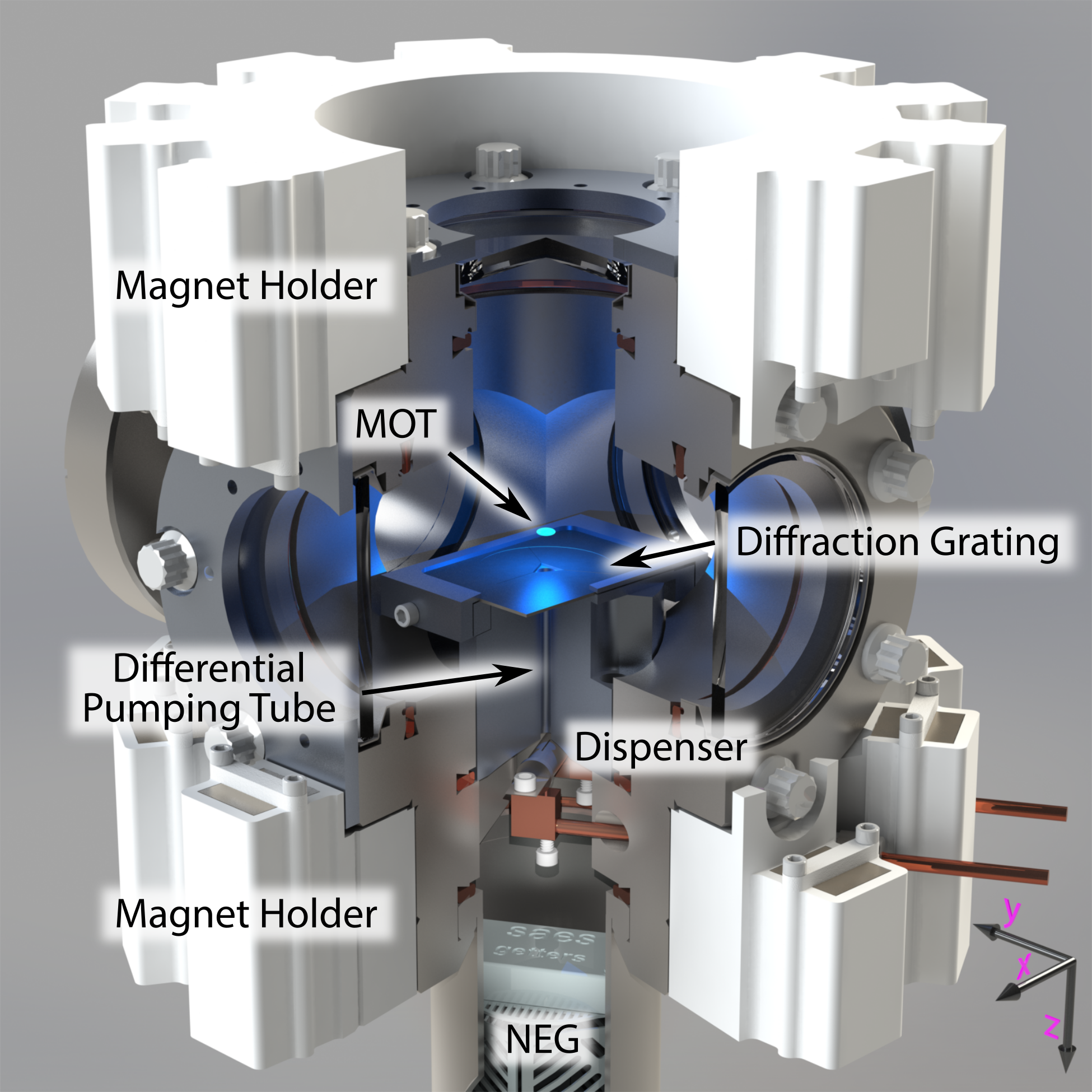
Our system, designed around a diffraction grating chip, mitigates the above issues associated with miniaturizing a MOT for alkaline-earth atoms (see Fig. 1). First, a 3 cm long differential pumping tube separates the vacuum chamber into two regions: the source chamber and the science chamber. The source chamber contains a vacuum pump and a low-outgassing dispenser Norrgard et al. (2018) that vaporizes strontium atoms. The atoms then travel through the differential pumping tube before entering the science chamber. Second, we create the magnetic field gradient for the MOT using permanent magnets, which are less complex than typical, water-cooled coils. The magnetic field gradient extends into the differential pumping tube, forming an effective Zeeman slower when combined with the input laser beam. Lastly, the first order diffraction efficiency of the grating we use is optimal at a wavelength of 600 nm, a middle ground between the two laser-cooling wavelengths (461 nm and 689 nm) for strontium. Our compact alkaline-earth grating MOT system also maintains the optical access and achieves the atom number necessary for future quantum devices.
II Apparatus
Our apparatus is shown in Fig. 1. The vacuum system is comprised of two chambers, separated by a 3 cm long, 3 mm diameter differential pumping tube with an N2 conductance of 0.11 L/s. The MOT is located in a science chamber with four CF275 viewports, and pumped with a 75 L/s ion pump (not shown). The source chamber is located below the differential pumping tube and is pumped with a 40 L/s non-evaporable getter (NEG) pump. Our source of Sr atoms is a 3D-printed titanium dispenser, described in Ref. Norrgard et al. (2018). We run a current between 12 A and 14 A through the dispenser, effusing strontium towards the differential pumping tube. Together, the source and science chambers are approximately 2.4 L in volume, although this estimate does not include the ion pump or the magnet holders. The base vacuum pressure of Pa in the science chamber could be improved by replacing the ion pump with an NEG pump, which would also reduce the size of the apparatus.
The grating chip is located above the differential pumping tube, and has a triangular hole through its center, allowing atoms to enter the science chamber. The grating chip was fabricated at the National Institute of Standards and Technology, and consists of three linear gratings arranged in a triangle. The parameters of the chip are the same as those in Ref. Barker et al. (2019), except with a trench depth of . This trench depth minimizes the order diffraction at 600 nm, which is between the 461 nm and 689 nm cooling transition wavelengths for strontium. Each linear grating diffracts 32(1) % of the normally-incident 461 nm light into each of the diffraction orders with an angle of . For normally incident, circularly polarized light, the stokes parameters of the grating chip at are , where () corresponds to () polarization defined relative to the plane of reflection for each linear grating.
Two sets of permanent magnets create the magnetic field for the MOT. They are housed in 3D-printed magnet holders made of polylactic acid (PLA) that are designed to produce a compact setup with high magnetic field gradients, as shown in Fig 1. Due to the geometric constraints of the vacuum chamber, the configuration of magnets is asymmetric, and the principal axes are rotated from those Fig 1. We achieve maximum gradients of {, , } along the {} axes, respectively, where and are rotated by from and . By removing magnets from the holders, we can lower the gradient to {, , } along the {} axes, respectively. The field gradient extends to mm, where corresponds to the and 40 mm corresponds to the position of the source.
A single laser beam, red-detuned from the transition at 461 nm, enters through the top viewport along the + axis and is normally incident upon the diffraction grating chip. The input MOT beam has a radius of 12 mm and a maximum power of 92 mW. For the 1SP1 transition with natural linewidth MHz, mW/cm2, giving a maximum peak . Intensities reported herein always refer to the peak intensity of the input beam. The central portion of the beam continues through the hole in the diffraction grating and through the differential pumping tube. This beam, combined with the magnetic field gradient, allows for a small amount of initial slowing of the atoms, similar to a Zeeman slower. Atoms can be lost from the MOT because the excited 1P1 state decays at a rate of 610 s-1 to the 1D2 state, which in turn decays to the 3P manifold. To mitigate the atom loss, two repump lasers, with wavelengths 679 nm and 707 nm, address the 3PS1 and 3PS1 transitions, respectively. More information on the repump scheme can be found in Ref. Vogel (1999). The repump beams are combined together on a 50/50 beam splitter, and then combined with the input MOT beam using a polarizing beam splitter.
We use absorption and fluorescence imaging along to characterize the MOT. Absorption images are taken after the MOT atom number equilibrates using a probe beam resonant with the 1S01P1 transition with . We use the atom number from the absorption images to calibrate the atom number extracted from fluorescence images taken during loading. The Labscript suite software Starkey et al. (2013) controls the experiment and data collection. More detailed information on the laser systems can be found in Ref. Pisenti (2019).
III Results
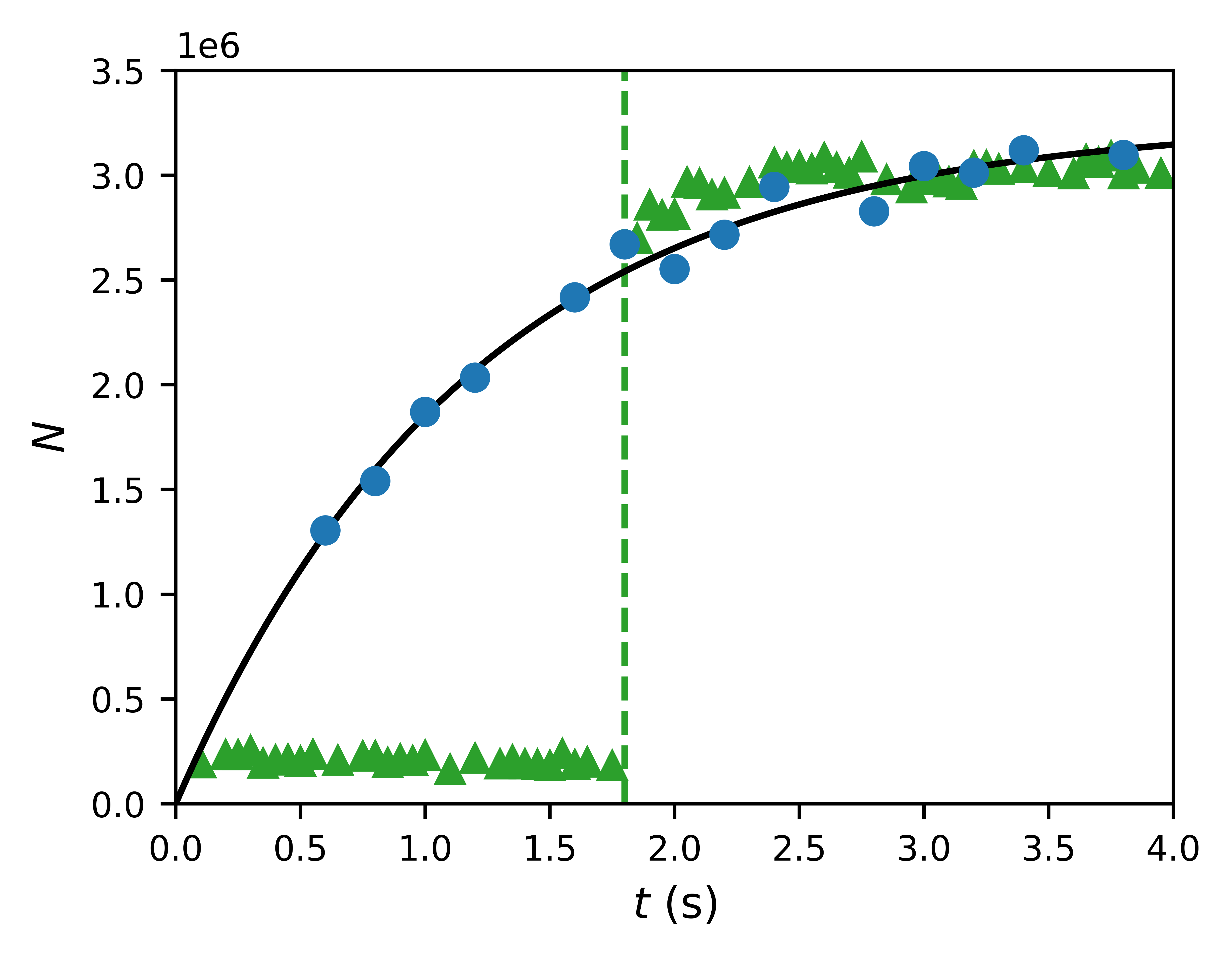
We measure atom number, loading rate, lifetime, and temperature to characterize the MOT. During each experimental shot we take a sequence of fluorescence images while the MOT loads and construct a loading curve. Fig. 2 shows typical loading curves at an axial magnetic field gradient of . For a MOT with no light assisted collisions, the loading rate , MOT lifetime , and equilibrium atom number , are extracted by fitting each loading curve to the single exponential
| (1) |
An example fit is shown with a solid black curve in Fig. 2. The quality of the fit to Eq. (1) indicates light assisted collisions and secondary scattering are negligible. At the higher gradient of 6.2 , we observe typical loading rates of s-1 and a vacuum-limited lifetime of s. We observe a similar loading curve at the lower gradient of mT/cm.

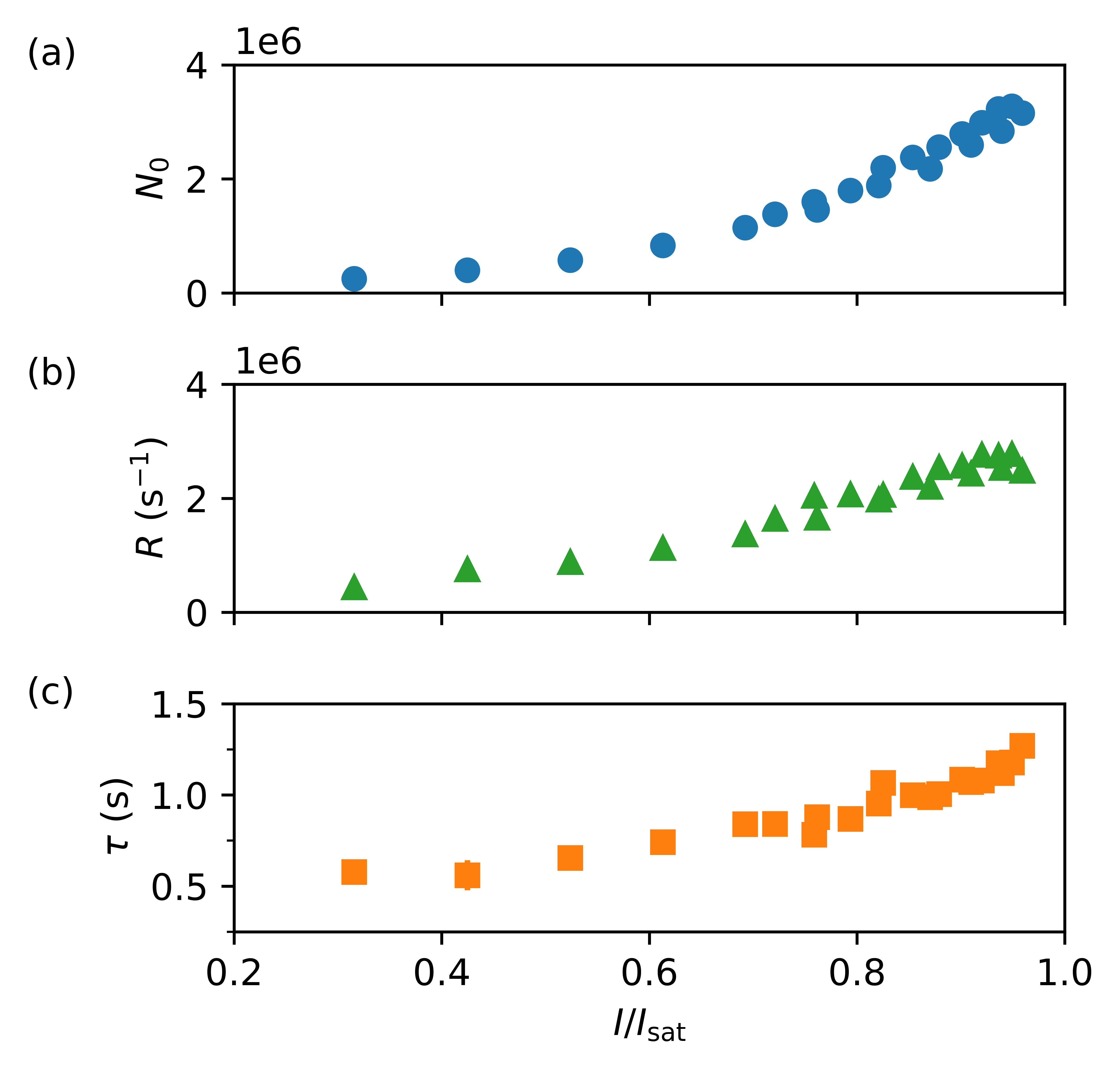
Fig. 3 and Fig. 4 show the MOT parameters as a function of detuning from resonance and intensity, respectively. We find the maximum atom number of approximately at a source current of 13 A and , a typical detuning for a conventional 6-beam Sr MOT Xu et al. (2003); Stellmer et al. (2009, 2013). As shown in Fig. 4(a), the atom number continues to increase with , even at our maximum intensity, indicating that more laser power would be beneficial. The increase in is only partially due to the increase in the loading rate , shown in Fig. 4(b). Part of the atom number increase is due to an increase in the lifetime with intensity, shown in Fig. 4(c). The lifetime increase suggests that the trap depth is increasing with laser power, which in turn increases the escape velocity for a Sr atom that undergoes a background gas collision Fagnan et al. (2009); Gensemer et al. (1997). However, the interplay between MOT temperature and tighter radial confinement with increasing intensity may also play a role.
We can also use the MOT to continuously load a magnetic trap, which consists of atoms that are trapped in the metastable 3P2 state. With strontium, the metastable magnetic trap is often used to increase the capture of rare isotopes and was key to the realization of quantum degeneracy Stellmer et al. (2009); de Escobar et al. (2009). By operating the MOT without repump light, atoms are shelved in the 3P2 state where they are trapped by the MOT magnetic field. When the repump light is turned on after atoms have accumulated in the magnetic trap, we see a sharp increase in the MOT atom number as shown in Fig. 2. The recovery confirms that atoms are being caught and held in the magnetic trap, however we do not see a transient enhancement above the equilibrium atom number as demonstrated elsewhere Nagel et al. (2003). Given our densities, and vacuum-limited atom number, we would not expect enhancement from magnetic trap loading. Adding a depumping laser could enhance the loading rate of the magnetic trap and increase the atom number Barker et al. (2015).
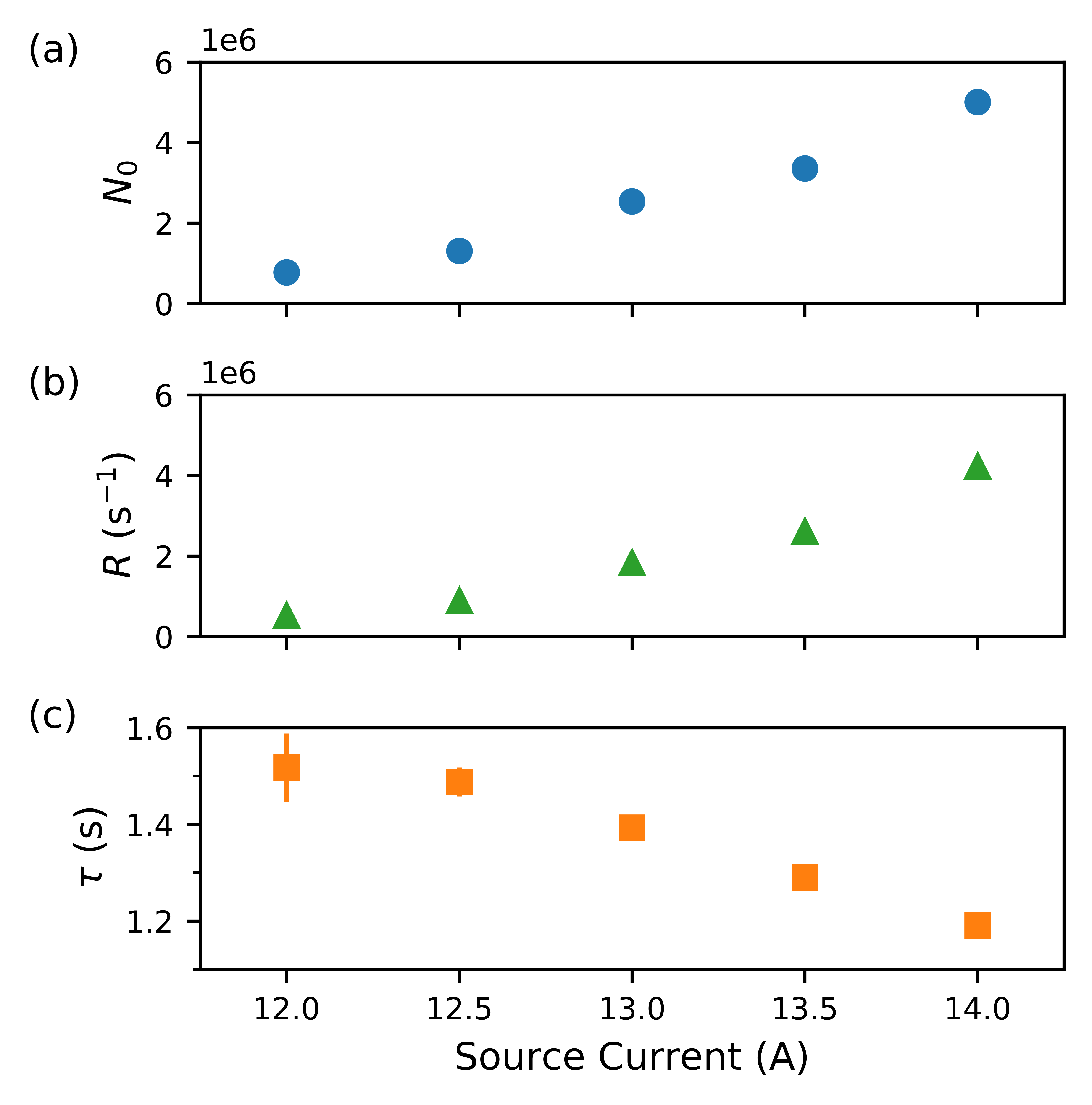
We investigate the effect of the source current on the atom number, loading rate, and lifetime, shown in Fig. 5. The source current sets the temperature of the source, which in turn determines both the vapor pressure and the average velocity of atoms leaving the source. At our highest achievable source current of A, limited by the ampacity of our electrical feedthroughs, we trap atoms, but have still not saturated the atom number. Based on the fit presented in Ref. Norrgard et al. (2018), we estimate the source temperature at 13 A to be over 600 . When the source current is increased from 0 A to 13 A, the vacuum pressure in the science chamber increases by Pa, suggesting that the differential pumping is sufficient. The increase in pressure is consistent with the small lifetime decrease shown in Fig. 5(c).
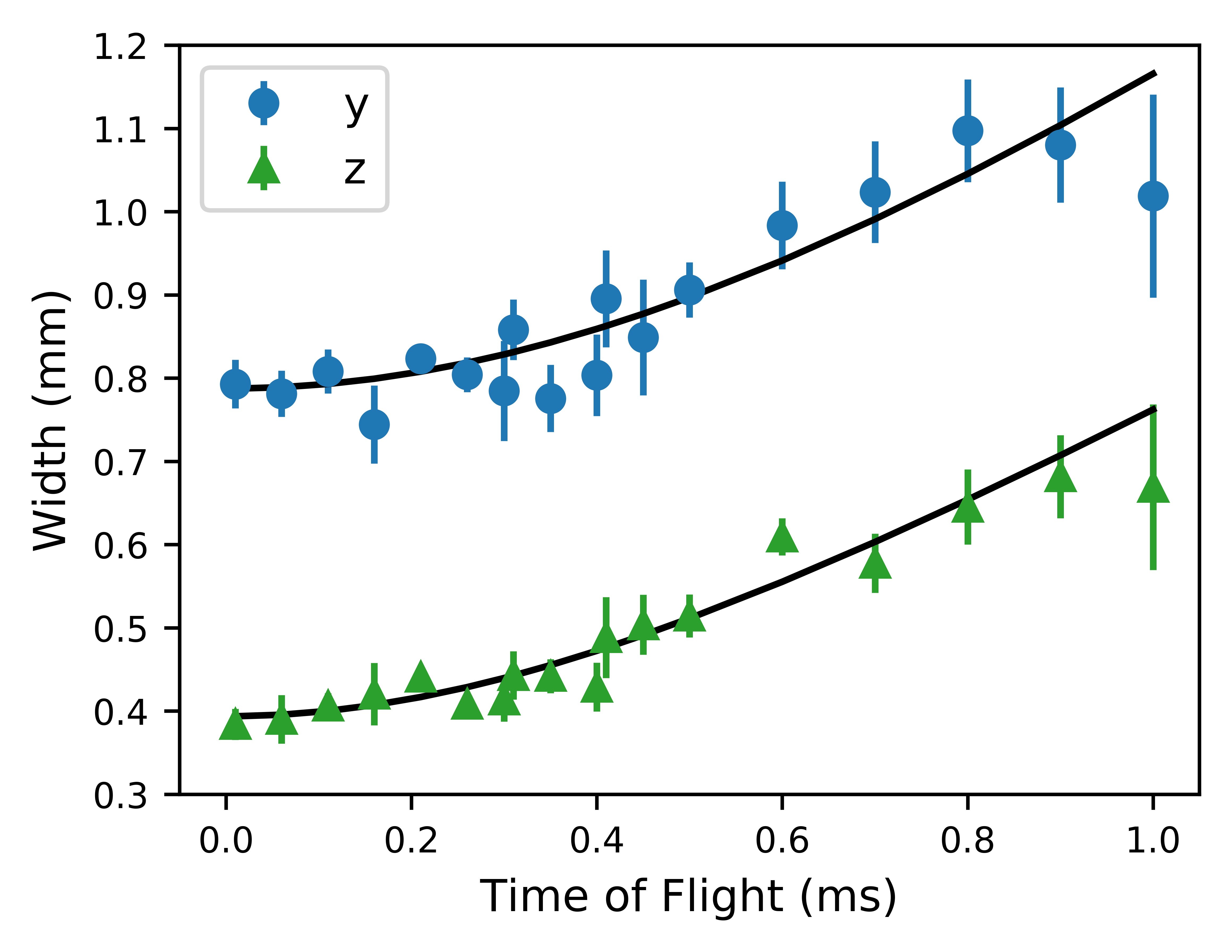
To determine the temperature of the MOT, we measure the width of the atomic cloud as it expands in time of flight, shown in Fig. 6. A Gaussian fit extracts the root-mean-square (rms) width, w, of the cloud in both the and directions. The extracted widths are binned by time of flight, and the error bars are calculated from the standard error about the mean. We fit the data to , where is the initial rms width of the cloud, is the rms velocity, is Boltzmann’s constant, is the atomic mass, and is the temperature of the atomic cloud. The temperature is 7.8(9) mK and 4.6(4) mK for and , respectively, which is consistent with a conventional six-beam MOT Xu et al. (2003). The temperature is not equal in the two dimensions because the diffusion coefficient and velocity damping constant are different in the axial and radial directions in a grating MOT. For our MOT, the ratio of the temperatures along and is , consistent with the ratio of from the theory in Ref. McGilligan et al. (2015).
While the discussion has focused on trapping 88Sr, strontium has a number of stable isotopes. The isotope abundances for strontium are 82.58%, 7.00%, 9.86%, and 0.56% for 88Sr, 87Sr, 86Sr, and 84Sr, respectively. Our setup can also trap around atoms of 86Sr at a source current of 13 A, consistent with the abundances above. Likewise, we would also expect to trap around atoms of 87Sr, but were unable to realize a MOT of 87Sr. The hyperfine structure of 87Sr poses at least two complications. First, we might not have sufficient repump power to adequately address all necessary hyperfine transitions Boyd (2007). Second, the hyperfine structure combined with the non-trivial geometry and polarizations of the grating MOT may significantly weaken the confining forces Mukaiyama et al. (2003); Lee et al. (2013). The theoretical details of the latter are beyond the scope of this work and will be presented in a future publication.
IV Discussion
We have realized a grating MOT of alkaline-earth atoms in a compact 2.4 L apparatus. Our permanent magnet design supplies the necessary field gradients for the MOT and allows for a degree of tunability, while the differential pumping tube limits outgassing from the hot source. The MOT traps up to atoms of 88Sr at a loading rate of s-1, with a lifetime of approximately 1 s. We also observe MOTs of 86Sr with atoms, consistent with the relative isotopic abundance.
In the future, upgrades to our apparatus could be made to improve the performance of the MOT and decrease the size of the system. We could improve the quality of the vacuum and reduce the size of the apparatus by replacing the ion pump with another NEG pump. Improving the quality of the vacuum would increase atom number and lifetime, potentially allowing us to observe a MOT of 84Sr. The system could be further miniaturized by using a fiber-coupled and photonically integrated chip to expand the MOT beam to the appropriate size without additional optics Yulaev et al. (2019); Kim et al. (2018). By incorporating electromagnets with our permanent magnet assembly, we could adjust the magnetic field gradient to allow transfer of the atoms to a MOT operating on the narrow 1SP1 transition. The grating has good diffraction efficiency at both cooling wavelengths, and the diffracted beams have sufficient overlap to facilitate transfer between the MOTs.
The implementation of field-deployable quantum devices relies on compact systems. Alkaline-earth-based quantum sensors have been proposed as platforms for atom interferometers and atomic clocks. Compact interferometers could be used for inertial navigation Hogan et al. (2008), and gravitational wave detection in space Graham et al. (2013). Deployable networks of optical clocks will be important for improved time and frequency metrology Parker (2012), and tests of fundamental physics Tino et al. (2007). Our results show that alkaline-earth grating MOTs are a promising step towards the development of compact optical clocks and other quantum devices.
Acknowledgements
Ananya Sitaram and Peter Elgee contributed equally to this work. We thank Francisco Salces Carcoba and Hector Sosa Martinez, for their careful reading of the manuscript. We also thank the NIST Center for Nanoscale Science and Technology NanoFab staff for allowing us to use the facility to fabricate grating chips. This work was partially supported by the NSF through the Physics Frontier Center at the Joint Quantum Institute.
References
- Bothwell et al. (2019) T. Bothwell, D. Kedar, E. Oelker, J. M. Robinson, S. L. Bromley, W. L. Tew, J. Ye, and C. J. Kennedy, JILA SrI optical lattice clock with uncertainty of , Metrologia 56, 065004 (2019).
- Hinkley et al. (2013) N. Hinkley, J. A. Sherman, N. B. Phillips, M. Schioppo, N. D. Lemke, K. Beloy, M. Pizzocaro, C. W. Oates, and A. D. Ludlow, An Atomic Clock with Instability, Science 341, 1215 (2013).
- Sorrentino et al. (2010) F. Sorrentino, Y.-H. Lien, G. Rosi, L. Cacciapuoti, M. Prevedelli, and G. M. Tino, Sensitive gravity-gradiometry with atom interferometry: progress towards an improved determination of the gravitational constant, New Journal of Physics 12, 095009 (2010).
- Graham et al. (2013) P. W. Graham, J. M. Hogan, M. A. Kasevich, and S. Rajendran, New Method for Gravitational Wave Detection with Atomic Sensors, Physical Review Letters 110, 171102 (2013), arXiv:1206.0818 .
- Vutha (2015) A. Vutha, Optical frequency standards for gravitational wave detection using satellite Doppler velocimetry, New Journal of Physics 17, 063030 (2015).
- Parker (2012) T. E. Parker, Invited Review Article: The uncertainty in the realization and dissemination of the SI second from a systems point of view, Review of Scientific Instruments 83, 021102 (2012).
- Lee et al. (1996) K. I. Lee, J. A. Kim, H. R. Noh, and W. Jhe, Single-beam atom trap in a pyramidal and conical hollow mirror., Optics Letters 21, 1177 (1996).
- Bowden et al. (2019) W. Bowden, R. Hobson, I. R. Hill, A. Vianello, M. Schioppo, A. Silva, H. S. Margolis, P. E. Baird, and P. Gill, A pyramid MOT with integrated optical cavities as a cold atom platform for an optical lattice clock, Scientific Reports 9, 1 (2019), 1907.13429 .
- Pollock et al. (2009) S. Pollock, J. P. Cotter, A. Laliotis, and E. A. Hinds, Integrated magneto-optical traps on a chip, Optics Express 17, 14109 (2009).
- Vangeleyn et al. (2009) M. Vangeleyn, P. F. Griffin, E. Riis, and A. S. Arnold, Single-laser, one beam, tetrahedral magneto-optical trap, Optics Express 17, 13601 (2009).
- Vangeleyn et al. (2010) M. Vangeleyn, P. F. Griffin, E. Riis, and A. S. Arnold, Laser cooling with a single laser beam and a planar diffractor, Optics Letters 35, 3453 (2010).
- Lee et al. (2013) J. Lee, J. A. Grover, L. A. Orozco, and S. L. Rolston, Sub-Doppler cooling of neutral atoms in a grating magneto-optical trap, J. Opt. Soc. Am. B 30, 2869 (2013).
- Nshii et al. (2013) C. C. Nshii, M. Vangeleyn, J. P. Cotter, P. F. Griffin, E. A. Hinds, C. N. Ironside, P. See, A. G. Sinclair, E. Riis, and A. S. Arnold, A surface-patterned chip as a strong source of ultracold atoms for quantum technologies, Nature Nanotechnology 8, 321 (2013).
- Barker et al. (2019) D. S. Barker, E. B. Norrgard, N. N. Klimov, J. A. Fedchak, J. Scherschligt, and S. Eckel, Single-Beam Zeeman Slower and Magneto-Optical Trap Using a Nanofabricated Grating, Physical Review Applied 11, 1 (2019).
- Koller et al. (2017) S. B. Koller, J. Grotti, S. Vogt, A. Al-Masoudi, S. Dörscher, S. Häfner, U. Sterr, and C. Lisdat, Transportable Optical Lattice Clock with Uncertainty, Physical Review Letters 118, 073601 (2017).
- Norrgard et al. (2018) E. B. Norrgard, D. S. Barker, J. A. Fedchak, N. Klimov, J. Scherschligt, and S. P. Eckel, Note: A 3D-printed alkali metal dispenser, Review of Scientific Instruments 89, 056101 (2018).
- Vogel (1999) K. R. Vogel, Laser cooling on a narrow atomic transition and measurement of the two-body cold collision loss rate in a strontium magneto-optical trap, Ph.D. thesis, University of Colorado (1999).
- Starkey et al. (2013) P. T. Starkey, C. J. Billington, S. P. Johnstone, M. Jasperse, K. Helmerson, L. D. Turner, and R. P. Anderson, A scripted control system for autonomous hardware-timed experiments, Review of Scientific Instruments 84, 085111 (2013).
- Pisenti (2019) N. C. Pisenti, Isotope Shift Spectroscopy of Ultracold Strontium, Ph.D. thesis, University of Maryland (2019).
- Xu et al. (2003) X. Xu, T. H. Loftus, J. L. Hall, A. Gallagher, and J. Ye, Cooling and trapping of atomic strontium, J. Opt. Soc. Am. B 20, 968 (2003).
- Stellmer et al. (2009) S. Stellmer, M. K. Tey, B. Huang, R. Grimm, and F. Schreck, Bose-einstein condensation of strontium, Phys. Rev. Lett. 103, 200401 (2009).
- Stellmer et al. (2013) S. Stellmer, R. Grimm, and F. Schreck, Production of quantum-degenerate strontium gases, Phys. Rev. A 87, 013611 (2013).
- Fagnan et al. (2009) D. E. Fagnan, J. Wang, C. Zhu, P. Djuricanin, B. G. Klappauf, J. L. Booth, and K. W. Madison, Observation of quantum diffractive collisions using shallow atomic traps, Phys. Rev. A 80, 022712 (2009).
- Gensemer et al. (1997) S. D. Gensemer, V. Sanchez-Villicana, K. Y. N. Tan, T. T. Grove, and P. L. Gould, Trap-loss collisions of and dependence on trap parameters, Phys. Rev. A 56, 4055 (1997).
- de Escobar et al. (2009) Y. N. M. de Escobar, P. G. Mickelson, M. Yan, B. J. DeSalvo, S. B. Nagel, and T. C. Killian, Bose-einstein condensation of , Phys. Rev. Lett. 103, 200402 (2009).
- Nagel et al. (2003) S. B. Nagel, C. E. Simien, S. Laha, P. Gupta, V. S. Ashoka, and T. C. Killian, Magnetic trapping of metastable $^{3}P_{2}$ atomic strontium, Physical Review A 67, 011401(R) (2003).
- Barker et al. (2015) D. S. Barker, B. J. Reschovsky, N. C. Pisenti, and G. K. Campbell, Enhanced magnetic trap loading for atomic strontium, Phys. Rev. A 92, 043418 (2015).
- McGilligan et al. (2015) J. P. McGilligan, P. F. Griffin, E. Riis, and A. S. Arnold, Phase-space properties of magneto-optical traps utilising micro-fabricated gratings, Opt. Express 23, 8948 (2015).
- Boyd (2007) M. M. Boyd, High Precision Spectroscopy of Strontium in an Optical Lattice: Towards a New Standard for Frequency and Time, Ph.D. thesis, University of Colorado, Boulder (2007).
- Mukaiyama et al. (2003) T. Mukaiyama, H. Katori, T. Ido, Y. Li, and M. Kuwata-Gonokami, Recoil-limited laser cooling of atoms near the fermi temperature, Phys. Rev. Lett. 90, 113002 (2003).
- Yulaev et al. (2019) A. Yulaev, W. Zhu, C. Zhang, D. A. Westly, H. J. Lezec, A. Agrawal, and V. Aksyuk, Metasurface-Integrated Photonic Platform for Versatile Free-Space Beam Projection with Polarization Control, ACS Photonics 6, 2902 (2019).
- Kim et al. (2018) S. Kim, D. A. Westly, B. J. Roxworthy, Q. Li, A. Yulaev, K. Srinivasan, and V. A. Aksyuk, Photonic waveguide to free-space Gaussian beam extreme mode converter, Light: Science and Applications 7, 10.1038/s41377-018-0073-2 (2018), arXiv:1803.08124 .
- Hogan et al. (2008) J. Hogan, D. Johnson, and M. Kasevich, Light-pulse atom interferometry, Proc. Int. School Phys. Enrico Fermi 168 (2008).
- Tino et al. (2007) G. Tino, L. Cacciapuoti, K. Bongs, C. Bordé, P. Bouyer, H. Dittus, W. Ertmer, A. Görlitz, M. Inguscio, A. Landragin, P. Lemonde, C. Lammerzahl, A. Peters, E. Rasel, J. Reichel, C. Salomon, S. Schiller, W. Schleich, K. Sengstock, and M. Wilkens, Atom interferometers and optical atomic clocks: New quantum sensors for fundamental physics experiments in space, Nuclear Physics B - Proceedings Supplements 166, 159 (2007).