Frozen Mode in Three-Way Periodic Microstrip Coupled Waveguide
Abstract
We demonstrate theoretically and experimentally that a periodic three-way microstrip coupled waveguide exhibits a stationary inflection point (SIP). The SIP is a third order exceptional point of degeneracy (EPD) where three eigenmodes of the guiding system coalesce to form a stationary frozen mode with zero group velocity. Here the frozen mode is shown in a reciprocal waveguide; therefore three coupled waveguides (called three-way waveguide) are required, supporting three modes in each direction. We illustrate the occurrence of the frozen mode regime by observing the dispersion diagram and by using the concept of coalescence parameter that is a measure of the separation of the three coalescing eigenvectors (polarization states). Results based on full-wave simulations and measurements demonstrate the coalescence of three modes and how this coalescence is not perfect due to the presence of losses in the microstrip structure at 2 GHz. The coalescence parameter is used to determine how close the three-way system is to the ideal frozen mode condition.
Index Terms:
Frozen modes, Coupled transmission line, Degeneracy, Stationary inflection point, Exceptional point. ††footnotetext: This material is based upon work supported by the Air Force Office of Scientific Research award number FA9550-18-1-0355 and by the National Science Foundation under Grant Number ECCS-171197. The authors would like to thank Dr. Ahmed Almutawa for his help with the fabrication and measurements of the structure. The authors are thankful to DS SIMULIA for providing CST Studio Suite that was instrumental in this study. (M. Nada and T. Mealy contributed equally to this work) (Corresponding author: Filippo Capolino) ††footnotetext: The authors are with the Department of Electrical Engineering and Computer Science, University of California at Irvine, Irvine, CA 92697 USA (e-mail: f.capolino@uci.edu).I Introduction
An exceptional point of degeneracy (EPD) is defined as the point in a system parameter space at which two or more system eigenmodes coalesce into a single degenerate mode [1], and the number of coalescing eigenmodes defines the order of the EPD. For instance, the cut off frequency in any uniform waveguide is a second order EPD resulting from the coalescence of two oppositely propagating modes [2], while the degenerate band edge (DBE) is a fourth order EPD [3, 4]. EPDs are obtained also in systems with gain and losses exploiting the concept of Parity-Time symmetry [5, 6], however in this paper we focus on gainless waveguides.
This paper is concerned with a third order EPD in lossless and gainless waveguides which is often referred to as the stationary inflection point (SIP) or frozen mode regime. Such an EPD is obtained due to the coalescence of three eigenmodes of which two are evanescent and one is propagating to form a frozen mode at which the group velocity is zero. Indeed, the group velocity preserves its direction for frequencies slightly smaller and higher than the SIP one, and this makes it beneficial for various possible applications such as amplifiers [7] and Lasers [8]. The SIP was obtained in photonic crystals that support only four modes (including both directions) through using magnetic materials to break reciprocity [9, 10, 11, 12, 13]. However, to obtain an SIP in reciprocal structures, at least three coupled waveguides are required that allow three modes to exist in each direction[14, 15]. The SIP has been obtained in reciprocal optical waveguides by introducing periodicity such as in periodic chain of coupled ring resonators that are side-coupled to a straight waveguide [4], three coupled waveguides with periodic perforations [16], coil resonators [17, 18], and also in [19] using coupled mode theory without referring to specific waveguide design.
In this paper, we introduce a novel design of a three-waye waveguide that exhibits an SIP at microwave frequencies shown in Fig. 1(a). In Sec. II, we provide the theoretical framework and demonstrate the occurrence of the SIP in a lossless three-way microstrip waveguide at 2 GHz using TL theory. In Sec. III, we demonstrate the existence of the SIP via full wave simulations and experimentally, with both results being in very good agreement. We also show how the coalescing parameter is useful to assess the coalescence of the three polarization state vectors.
II Frozen Mode in Lossless Three-Way Microstrip Waveguide Design
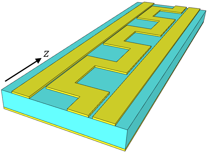
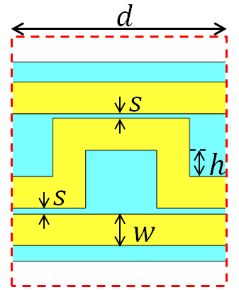
The periodic three-way reciprocal microstrip, shown in Fig. 1(a), exhibits a frozen mode, i.e., an SIP in its - dispersion diagram, where is the Bloch-wavenumber and is the angular frequency. The three-way waveguide comprises two uniform TLs that are coupled through a third serpentine-shaped TL as shown in Fig. 1(a), with the unit cell shown in 1(b). We assume that all the TLs have the same width so that the three individual TLs have a characteristic impedance of 50 Ohms (when uncoupled), the distance between coupled lines is , and the structure period is . To find the proper dimensions of the three-way microstrip so that it exhibits an SIP at 2 GHz, we consider first a lossless structure with substrate of a dielectric constant and height mm. We determine the TL dimensions using the quasi-static model in [20] by imposing the values of the desired characteristic impedance of 50 Ohms and the dielectric permittivity of the grounded dielectric substrate. The three-way microstrip supports six eigenmodes; three in each -direction. The proposed three-way microstrip shown here departs from the one in [13] because instead of breaking the system reciprocity using nonreciprocal magnetic materials, we introduce a third TL with periodic coupling to get the SIP while retaining the system reciprocity. We define a state vector to describe the evolution of the eigenmodes as , where denotes the transpose operation, and and with represent the voltage and the current in TL , respectively.
The evolution of the state vector of the periodic structure is described by , where is the transfer matrix (T-matrix) that translates the state vector from point to . The spatial evolution of the state vector across a unit cell of length is given by , where the unit-cell T-matrix . According to Floquet-Bloch theory, we look for periodic solutions of the state vector as where is the Floquet-Bloch complex wavenumber, that satisfy , with . The eigenvalue problem is then formulated as
| (1) |
where the eigenvalues , with are obtained by solving the dispersion characteristic equation , with being the identity matrix. Due to reciprocity, the determinant of is always equal to unity [21] which implies that the eigenvalues solutions of the characteristic equation must appear in reciprocal pairs. This means that if is a Floquet-Bloch wavenumber solution, then is also a solution, i.e., the six k-solutions must come in positive-negative pairs. Away from an EPD, the unit-cell T-matrix is diagonalizable hence it has six eigenvectors associated with six eigenvalues . However at the EPD, the T-matrix is not diagonalizable and is similar to a matrix containing two Jordan Blocks as shown in [4]. Since the waveguide has 6 eigenvalues, at the SIP frequency we have only two reciprocal eigenvalues and , and each of them has algebraic multiplicity 3 and geometrical multiplicity 1. Hence, the six Floquet-Bloch wavenumber solutions are and , and each one is repeated three times. The eigenvectors associated with degenerate eigenvalues are generalized eigenvectors obtained from , where is the order of the SIP degeneracy, i.e., the number of coalescing eigenvectors. Note that is the regular eigenvector associated with the degenerate eigenvalue .
The SIP is a mathematical concept that is never met perfectly in reality because losses and fabrication tolerances would inhibit the perfect coalescence. However, a system can operate in the vicinity of the frozen mode regime while retaining the unique physical properties of the three-mode degeneracy. In order to assess how close a system is to an EPD, we use the coalescence parameter concept developed in [22] , where the authors referred to it as figure of merit or hyperdistance. To better evaluate the coalescence between three eigenvectors, we normalize the eigenvector terms so that they all have the same unit as , with , and is a normalization impedance that is here considered to be equal to the TLs characteristic impedance.
The coalescence of the three eigenvetcors , and associated to the three positive wavenumbers in (1) is measured via the coalescence parameter
| (2) |
where is the angle between the two six-dimensional complex vectors and , and it is defined via the inner product , with the dagger symbol representing the complex conjugate transpose operation, and and denote their norms. The parameter is always positive and less than one, and indicates the perfect coalescence of the three eigenvectors, i.e., the system experiences an SIP.
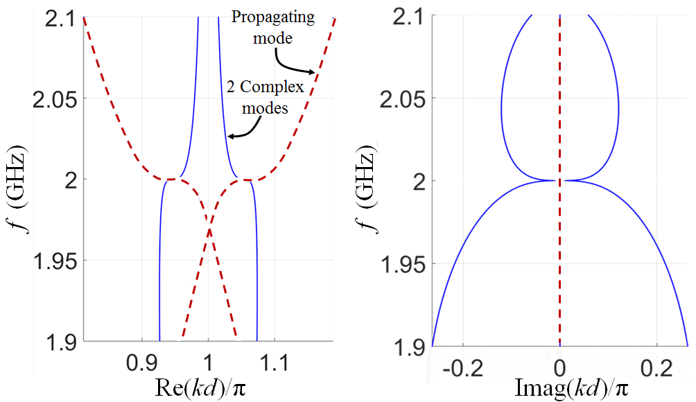
We build the transfer matrix of the unit-cell in Fig. 1(b) using transmission line analytic formulas by diving the waveguide into sections of uniform single/coupled transmission lines and we tuned the dimensions of the unit cell to minimize the three eignvectors coalescence parameter , where the eigenvecctors are calculated from the eigenvalue problem (1). The optimized lossless unit cell has dimensions mm, mm, mm, and a period mm, and it exhibits an SIP at 2 GHz as shown in Fig. 1(c), without using magnetic materials to break the system reciprocity.
At the SIP, the dispersion relation is approximated as , where is the angular frequency at which the three modes coalesce, is a constant that describes the flatness of the SIP. The group velocity and its derivative are zero at the SIP, i.e., , whereas the second derivative of the group velocity is non zero, i.e., .
III Experimental Verification of SIP and Full-Wave Simulations
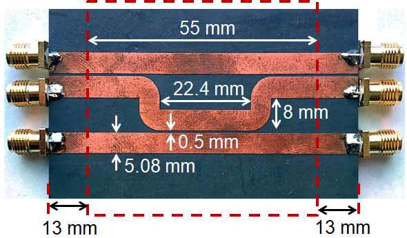
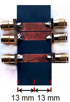
We verify the existence of the SIP in the three-way periodic microstrip shown in Fig. 1(a) both experimentally and via full-wave simulations. We used a grounded substrate (Roger5880) that has substrate loss of , whereas the metal layers have conductivity of S/m and thickness of The fabricated unit cell is shown in Fig. 2(a) including SMA connectors, where we have added extra extensions of mm on each side of the unit cell to deembed the effect of the SMA connectors. Indeed, the SMA connectors not only add extra length but also introduce high order evanescent modes due to the discontinuity [13]. We fabricated a “calibration” circuit with only the two added extra lengths as shown in Fig. 2(b), to deembed the SMA effects as follows.
The T-matrices of the two fabricated circuits, the one with the extra lengths and the calibration circuit, in Figs. 2(a) and (b) are and , respectively, where and are the T-matrices of the extra length and the SMA connectors on the right and left sides, respectively. Hence, we calculate a new T-matrix whose eigenvalues are the same of those of the unit-cell T-matrix , if is not singular, as shown in [23]; a related but different method is also shown in [13]. The transfer matrices and are obtained by transforming the scattering matrices associated to the 6-port circuits in Figs. 2(a) and (b).
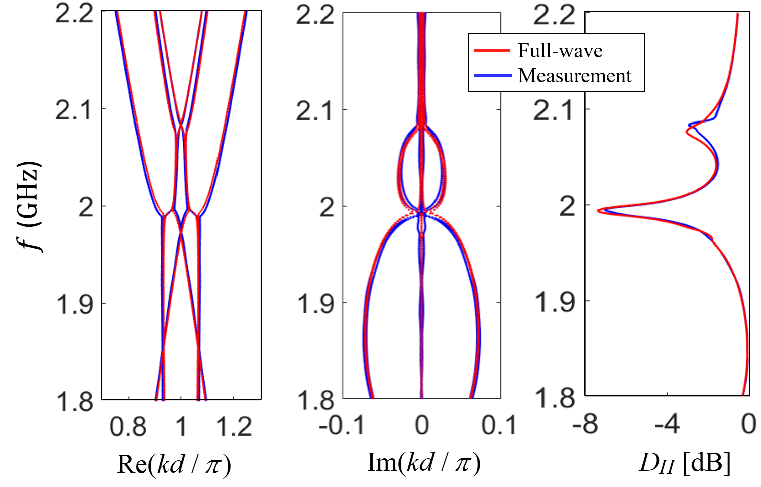
The scattering matrices are obtained via measurements using a Rohde & Schwarz Vector Network Analyzer (VNA) ZVA 67 and also via full-wave simulations based on the finite element method implemented in CST Studio Suite. The measured S-matrix is obtained through connecting two ports of the VNA to ports and of the unit cell, while the other four ports are terminated by 50 Ω loads so that we measure a S-matrix block . We change the ports and to cover all the combinations of the 6-ports circuit to construct the S-matrix from the obtained block matrices. Once the T-matrices and are obtained from the S-parameters, we calculate the unit-cell complex wavenumbers from the eigenvalues of following the method discussed in the previous section. The comparison between the measured and the simulated dispersion diagrams in Fig. 2(c) shows a good agreement. As mentioned previously, conductor, dielectric, and radiation losses slightly affect the coalescence of the three eigenmodes at the SIP. To quantify this effect, we calculate the coalescence parameter shown in Fig. 2(c) using the eigenvectors of the T-matrix obtained from both the measured and the numerically simulated unit-cell T-matrix. Note that the eigenvectors of and are not the same, yet they share the geometrical and algebraic multiplicities of the eigenvalues, see Ch. 7.2 in [24], so they demonstrate similar trends in their coalescence parameters. The dip at the SIP frequency in the well matched numerically and experimentally calculated coalescence parameter verifies the existence of the SIP.
IV Conclusion
We have proposed a three-way periodic microstrip waveguide geometry that exhibits an SIP in its dispersion diagram, without the need of breaking the system reciprocity. We have provided a theoretical model to describe the occurrence of the frozen mode regime through the coalescence parameter that quantifies the coalescence of the eigenvectors and also via the degeneracy in the complex wavenumber dispersion diagram. We have demonstrated the occurrence of the frozen mode regime using both full-wave simulations and scattering parameters measurements of a six-port unit cell. The SIP in periodic microstrip structures can serve various applications like distributed amplifiers [7], delay lines[25], pulse generators, and sensors.
References
- [1] A. Figotin and I. Vitebskiy, “Oblique frozen modes in periodic layered media,” Physical Review E, vol. 68, no. 3, p. 036609, 2003.
- [2] T. Mealy, A. F. Abdelshafy, and F. Capolino, “The degeneracy of the dominant mode in rectangular waveguide,” in 2019 United States National Committee of URSI National Radio Science Meeting (USNC-URSI NRSM), Boulder, CO, USA, 2019, pp. 1-2.
- [3] A. Figotin and I. Vitebskiy, “Gigantic transmission band-edge resonance in periodic stacks of anisotropic layers,” Physical review E, vol. 72, no. 3, p. 036619, 2005.
- [4] M. Y. Nada, M. A. Othman, and F. Capolino, “Theory of coupled resonator optical waveguides exhibiting high-order exceptional points of degeneracy,” Physical Review B, vol. 96, no. 18, p. 184304, 2017.
- [5] C. E. RÃŒter, K. G. Makris, R. El-Ganainy, D. N. Christodoulides, M. Segev, and D. Kip, “Observation of parity-time symmetry in optics,” Nature Physics, vol. 6, no. 3, pp. 192–195, Mar. 2010.
- [6] J. Schnabel, H. Cartarius, J. Main, G. Wunner, and W. D. Heiss, “-symmetric waveguide system with evidence of a third-order exceptional point,” Phys. Rev. A, vol. 95, p. 053868, May 2017.
- [7] F. Yazdi, M. A. K. Othman, M. Veysi, F. Capolino, and A. Figotin, “Third order modal degeneracy in waveguids: Features and application in amplifiers,” in 2017 USNC-URSI Radio Science Meeting (Joint with AP-S Symposium), July 2017, pp. 109–110.
- [8] H. Ramezani, S. Kalish, I. Vitebskiy, and T. Kottos, “Unidirectional lasing emerging from frozen light in nonreciprocal cavities,” Physical review letters, vol. 112, no. 4, p. 043904, 2014.
- [9] A. Figotin and I. Vitebsky, “Nonreciprocal magnetic photonic crystals,” Physical Review E, vol. 63, no. 6, p. 066609, 2001.
- [10] A. Figotin and I. Vitebskiy, “Electromagnetic unidirectionality in magnetic photonic crystals,” Physical Review B, vol. 67, no. 16, p. 165210, 2003.
- [11] G. Mumcu, K. Sertel, J. L. Volakis, I. Vitebskiy, and A. Figotin, “Rf propagation in finite thickness unidirectional magnetic photonic crystals,” IEEE Transactions on Antennas and Propagation, vol. 53, no. 12, pp. 4026–4034, Dec 2005.
- [12] M. B. Stephanson, K. Sertel, and J. L. Volakis, “Frozen modes in coupled microstrip lines printed on ferromagnetic substrates,” IEEE Microwave and Wireless Components Letters, vol. 18, no. 5, pp. 305–307, May 2008.
- [13] N. Apaydin, L. Zhang, K. Sertel, and J. L. Volakis, “Experimental Validation of Frozen Modes Guided on Printed Coupled Transmission Lines,” IEEE Transactions on Microwave Theory and Techniques, vol. 60, no. 6, pp. 1513–1519, Jun. 2012.
- [14] H. Li, I. Vitebskiy, and T. Kottos, “Frozen mode regime in finite periodic structures,” Phys. Rev. B, vol. 96, p. 180301, Nov 2017.
- [15] Z. M. Gan, H. Li, and T. Kottos, “Effects of disorder in frozen-mode light,” Optics Letters, vol. 44, no. 11, pp. 2891–2894, 2019.
- [16] R. Almhmadi and K. Sertel, “Frozen-light modes in 3-way coupled silicon ridge waveguides,” in 2019 United States National Committee of URSI National Radio Science Meeting (USNC-URSI NRSM), Jan 2019, pp. 1–2.
- [17] M. Sumetsky, “Uniform coil optical resonator and waveguide: transmission spectrum, eigenmodes, and dispersion relation,” Opt. Express, vol. 13, no. 11, pp. 4331–4340, May 2005.
- [18] J. Scheuer and M. Sumetsky, “Optical-fiber microcoil waveguides and resonators and their applications for interferometry and sensing,” Laser & Photonics Reviews, vol. 5, no. 4, pp. 465–478, 2011.
- [19] N. Gutman, C. Martijn de Sterke, A. A. Sukhorukov, and L. C. Botten, “Slow and frozen light in optical waveguides with multiple gratings: Degenerate band edges and stationary inflection points,” Physical Review A, vol. 85, no. 3, p. 033804, Mar. 2012.
- [20] H. A. Wheeler, “Transmission-line properties of parallel strips separated by a dielectric sheet,” IEEE Transactions on Microwave Theory and Techniques, vol. 13, no. 2, pp. 172–185, 1965.
- [21] V. Easwaran, V. Gupta, and M. Munjal, “Relationship between the impedance matrix and the transfer matrix with specific reference to symmetrical, reciprocal and conservative systems,” Journal of Sound and Vibration, vol. 161, no. 3, pp. 515 – 525, 1993.
- [22] A. F. Abdelshafy, M. A. K. Othman, D. Oshmarin, A. T. Almutawa, and F. Capolino, “Exceptional points of degeneracy in periodic coupled waveguides and the interplay of gain and radiation loss: Theoretical and experimental demonstration,” IEEE Transactions on Antennas and Propagation, vol. 67, no. 11, pp. 6909–6923, 2019.
- [23] T. Mealy and F. Capolino, “General conditions to realize exceptional points of degeneracy in two uniform coupled transmission lines,” arXiv preprint arXiv:2003.04215, 2020.
- [24] C. D. Meyer, Matrix analysis and applied linear algebra. Philadelphia: SIAM: Society for Industrial and Applied Mathematics, Feb. 2001.
- [25] B. Paul, N. K. Nahar, and K. Sertel, “Harnessing the frozen-mode in coupled silicon ridge waveguides for true time delay applications,” in 2019 International Conference on Electromagnetics in Advanced Applications (ICEAA), Granada, Spain, 2019, pp. 0552–0552.