|
|
|
The Laser-hybrid Accelerator for Radiobiological Applications
The LhARA collaboration
G. Aymar 1, T. Becker 2, S. Boogert 3, M. Borghesi 4, R. Bingham 5,1, C. Brenner 1, P.N. Burrows 6, T. Dascalu 7, O.C. Ettlinger 8, S. Gibson 3, T. Greenshaw 9, S. Gruber 10, D. Gujral 11, C. Hardiman 11, J. Hughes 9, W.G. Jones 7,20, K. Kirkby 12, A. Kurup 7, J-B. Lagrange 1, K. Long 7,1, W. Luk 7, J. Matheson 1, P. McKenna 5,14, R. Mclauchlan 11, Z. Najmudin 8, H.T. Lau 7, J.L. Parsons 9,21, J. Pasternak 7,1, J. Pozimski 7,1, K. Prise 4, M. Puchalska 13, P. Ratoff 14, G. Schettino15,19, W. Shields 3, S. Smith 16, J. Thomason 1, S. Towe 17, P. Weightman 9, C. Whyte 5,14, R. Xiao 18
| 1. | STFC Rutherford Appleton Laboratory, Harwell Oxford, Didcot, OX11 0QX, UK |
| 2. | Maxeler Technologies Limited, 3 Hammersmith Grove, London W6 0ND, UK |
| 3. | John Adams Institute, Royal Holloway, University of London, Egham, Surrey, TW20 0EX, UK |
| 4. | Queens University Belfast, University Road, Belfast, BT7 1NN, Northern Ireland, UK |
| 5. | Department of Physics, SUPA, University of Strathclyde, 16 Richmond Street, Glasgow, G1 1XQ, UK |
| 6. | John Adams Institute, University of Oxford, Denys Wilkinson Building, Keble Road, Oxford OX1 3RH, UK |
| 7. | Imperial College London, Exhibition Road, London, SW7 2AZ, UK |
| 8. | John Adams Institute, Imperial College London, Exhibition Road, London, SW7 2AZ, UK |
| 9. | University of Liverpool, Liverpool L3 9TA, UK |
| 10. | Christian Doppler Laboratory for Medical Radiation Research for Radiation Oncology, Medical University of Vienna, Spitalgasse 23, |
| 1090 Vienna, Austria | |
| 11. | Imperial College NHS Healthcare Trust, The Bays, South Wharf Road, St Mary’s Hospital, London W2 1NY, UK |
| 12. | University of Manchester, Oxford Road, Manchester, M13 9PL, UK |
| 13. | Technische Universität Wien, Atominstitut, Stadionallee 2, 1020 Vienna, Austria |
| 14. | Cockcroft Institute, Daresbury Laboratory, Sci-Tech Daresbury, Daresbury, Warrington, WA4 4AD, UK |
| 15. | National Physical Laboratory, Hampton Road, Teddington, Middlesex, TW11 0LW, UK |
| 16. | STFC Daresbury Laboratory, Daresbury, Cheshire, WA4 4AD, UK |
| 17. | Leo Cancer Care, Broadview, Windmill Hill, Hailsham, East Sussex, BN27 4RY, UK |
| 18. | Corerain Technologies, 14F, Changfu Jinmao Building (CFC), Trade-free Zone, Futian District, Shenzhen, Guangdong, China |
| 19. | University of Surrey, 388 Stag Hill, Guilford, GU2 7XH, UK |
| 20. | Imperial Patient and Public Involvement Group (IPPIG), Imperial College London, Exhibition Road, London, SW7 2AZ, UK |
| 21. | The Clatterbridge Cancer Centre, Bebington, CH63 4JY, UK |
| † | Corresponding author, Email: a.kurup@imperial.ac.uk |
Preprint submitted to Frontiers in Physics, Medical Physics and Imaging
Abstract
The ‘Laser-hybrid Accelerator for Radiobiological Applications’, LhARA, is conceived as a novel, uniquely-flexible facility dedicated to the study of radiobiology. The technologies demonstrated in LhARA, which have wide application, will be developed to allow particle-beam therapy to be delivered in a completely new regime, combining a variety of ion species in a single treatment fraction and exploiting ultra-high dose rates. LhARA will be a hybrid accelerator system in which laser interactions drive the creation of a large flux of protons or light ions that are captured using a plasma (Gabor) lens and formed into a beam. The laser-driven source allows protons and ions to be captured at energies significantly above those that pertain in conventional facilities, thus evading the current space-charge limit on the instantaneous dose rate that can be delivered. The laser-hybrid approach, therefore, will allow the vast “terra incognita” of the radiobiology that determines the response of tissue to ionising radiation to be studied with protons and light ions using a wide variety of time structures, spectral distributions, and spatial configurations at instantaneous dose rates up to and significantly beyond the ultra-high dose-rate ‘FLASH’ regime.
It is proposed that LhARA be developed in two stages. In the first stage, a programme of in vitro radiobiology will be served with proton beams with energies between 10 MeV and 15 MeV. In stage two, the beam will be accelerated using a fixed-field accelerator (FFA). This will allow experiments to be carried out in vitro and in vivo with proton beam energies of up to 127 MeV. In addition, ion beams with energies up to 33.4 MeV per nucleon will be available for in vitro and in vivo experiments. This paper presents the conceptual design for LhARA and the R&D programme by which the LhARA consortium seeks to establish the facility.
Lay summary
It is well established that radiation therapy (RT) is an effective treatment for many types of cancer. Most treatments are delivered by machines that accelerate electrons which are then used to produce a beam of high-energy photons (X-rays) which are directed at a tumour to kill cancer cells. However, healthy tissue anywhere in the path of the photon beam is also irradiated and so can be damaged. Modern X-ray therapy is able to reduce this damage by using several beams at different angles.
Recent years have seen the use of a new type of machine in which protons are accelerated to produce proton beams (rather than photon beams) which are directed at a tumour. These proton beams can be arranged to deposit almost all of their energy in a small volume within a tumour so they cause little damage to healthy tissue; a major advantage over photon beams. But proton machines are large and expensive, so there is a need for the development of proton machines that are smaller, cheaper and more flexible in how they can be used.
The LhARA project is aimed at the development of such proton machines using a new approach based on high powered lasers. Such new machines could also make it easier to deliver the dose in very short high-intensity pulses and as a group of micro-beams—exciting recent research has shown that this brings improved effectiveness in killing cancer cells while sparing healthy tissue. The technology to be proved in LhARA should enable a course of RT to be delivered in days rather than weeks and should be more effective.
Scientifically, there is a need to understand much better the basic processes by which radiation interacts with biological matter to kill cancer cells—the investigation of these processes involves physics as well as biology. Thus the most important aim of LhARA is to pursue this radiobiological research in new regimes and from this to develop better treatments. LhARA will also pursue technological research into laser-hybrid accelerators.
1 Introduction
Cancer is the second most common cause of death globally [1]. In 2018, 18.1 million new cancer cases were diagnosed, 9.6 million people died of cancer-related disease, and 43.8 million people were living with cancer [2, 3]. It is estimated that 26.9 million life-years could be saved in low- and middle-income countries if radiotherapy capacity could be scaled up [4]. Novel techniques incorporated in facilities that are at once robust, automated, efficient, and cost-effective are required to deliver the required scale-up in provision.
Radiation therapy (RT), a cornerstone of cancer treatment, is used in over 50% of cancer patients [5]. The most frequently used types of radiotherapy employ photon or electron beams with MeV-scale energies. Proton and ion beams offer substantial advantages over X-rays because the bulk of the beam energy is deposited in the Bragg peak. This allows dose to be conformed to the tumour while sparing healthy tissue and organs at risk. The benefits of proton and ion-beam therapy (PBT) are widely recognised. PBT today is routinely delivered in fractions of Gy per day over several weeks; each fraction being delivered at a rate of Gy/minute deposited uniformly over the target treatment volume. Exciting evidence of therapeutic benefit has recently been reported when dose is delivered at ultra-high dose-rate, Gy/s (“FLASH” RT) [6, 7], or provided in multiple micro-beams with diameter less than 1 mm distributed over a grid with inter-beam spacing of mm [8]. However, the radiobiological mechanisms by which the therapeutic benefit is generated are not entirely understood.
LhARA, the Laser-hybrid Accelerator for Radiobiological Applications, is conceived as the new, highly flexible, source of radiation that is required to explore the vast “terra incognita” of the mechanisms by which the biological response to ionising radiation is determined by the physical characteristics of the beam. A high-power pulsed laser will be used to drive the creation of a large flux of protons or light ions which are captured and formed into a beam by strong-focusing plasma lenses. The laser-driven source allows protons and ions to be captured at energies significantly above those that pertain in conventional facilities, thus evading the current space-charge limit on the instantaneous dose rate that can be delivered. The plasma (Gabor) lenses provide the same focusing strength as high-field solenoids at a fraction of the cost. Rapid acceleration will be performed using a fixed-field alternating-gradient accelerator (FFA) thereby preserving the unique flexibility in the time, energy, and spatial structure of the beam afforded by the laser-driven source.
We propose that LhARA be developed in two stages. In the first stage, the laser-driven beam, captured and transported using plasma lenses and bending magnets, will serve a programme of in vitro radiobiology with proton beams of energy of up to 15 MeV. In stage two, the beam will be accelerated using an FFA. This will allow experiments to be carried out in vitro and in vivo with proton-beam energies of up to 127 MeV. Ion beams (including C6+) with energies up to 33.4 MeV per nucleon will also be available.
The laser pulse that initiates the production of protons or ions at LhARA may be triggered at a repetition rate of up to 10 Hz. The time structure of the beam may therefore be varied to interrupt the chemical and biological pathways that determine the biological response to ionising radiation with 10 ns to 40 ns long proton or ion bunches repeated at intervals as small as 100 ms. The technologies chosen to capture, transport, and accelerate the beam in LhARA have been made so that this unique capability is preserved. The LhARA beam may be used to deliver an almost uniform dose distribution over a circular area with a maximum diameter of between 1 cm and 3 cm. Alternatively the beam can be focused to a spot with diameter of mm.
The technologies demonstrated in LhARA have the potential to be developed to make “best in class” treatments available to the many. The laser-hybrid approach will allow radiobiological studies and eventually radiotherapy to be carried out in completely new regimes, delivering a variety of ion species in a broad range of time structures, spectral distributions, and spatial configurations at instantaneous dose rates up to and potentially significantly beyond the current ultra-high dose-rate “FLASH” regime.
The LhARA consortium is the multidisciplinary collaboration of clinical oncologists, medical and academic physicists, biologists, engineers, and industrialists required to deliver such a transformative particle-beam system. With its “pre Conceptual Design Report” (pre-CDR) [9] the consortium lays out its concept for LhARA, its potential to serve a ground-breaking programme of radiobiology, and the technological advances that will be made in its execution. The work presented in the LhARA pre-CDR lays the foundations for the development of full conceptual and technical designs for the facility. The pre-CDR also contains a description of the R&D that is required to demonstrate the feasibility of critical components and systems. This paper presents a summary of the contents of the pre-CDR and lays out the vision of the consortium.
2 Motivation
Conventional (X-ray) RT is one of the most effective cancer treatments, particularly for solid tumours including head and neck tumours and glioblastoma. The dose delivered using X-rays falls approximately exponentially with depth; this characteristic implies a fundamental limit on the maximum dose that can be delivered to the tumour without delivering an unacceptably large dose to healthy tissue. For a given treatment beam-entry point, tumours that lie deep within the patient will receive a dose significantly lower than that delivered to the healthy tissues through which the beam passes on its way to the treatment site. X-rays that pass through the tumour will also deliver a dose to the tissues that lie behind. Dose delivered to healthy tissues can cause the death of the healthy cells and create adverse side effects. Furthermore, the maximum X-ray dose that can be delivered is limited by the presence of sensitive organs such as the brain and spinal cord. This situation is particularly acute in infants for whom dose to healthy tissue, sensitive organs, and bone can lead to developmental issues and a higher probability of secondary malignancies later in life.
RT delivered using protons and ions, particle-beam therapy (PBT), has the potential to overcome some of the fundamental limitation of X-rays in cancer treatment [10]. The physics of the interaction between ionising radiation and tissue determines the radiobiological effect. Energy loss through ionisation is the dominant mechanism at the beam energies relevant to PBT. The energy lost per unit distance travelled, the linear energy transfer (LET), increases as the protons or ions slow down. At low velocity, the rate of increase in LET is extremely rapid. This generates a ‘Bragg peak’ in the energy deposited at the maximum range of the beam just as the protons or ions come to rest. In contrast to photons, this characteristic allows the dose delivered to healthy tissue behind the Bragg peak to be reduced to zero for protons, and almost to zero for carbon ions. Scanning the Bragg peak over the tumour volume enables an increase in dose to the tumour while, in comparison to X-ray therapy, sparing tissues in front of the tumour. By choosing carefully the treatment fields, dose to sensitive organs can be reduced significantly compared to an equivalent treatment with photons, thus improving patient outcomes. The Particle Therapy Co-Operative Group (PTCOG) currently lists 90 proton therapy facilities and 12 carbon ion therapy facilities. These facilities are located predominantly in high-income countries [11]. Low- and middle-income countries (LMIC) are relatively poorly served, indeed nearly 70% of cancer patients globally do not have access to RT [5]. Novel RT techniques incorporated in facilities that are robust, automated, efficient, and cost-effective are therefore required to deliver the necessary scale-up in provision. This presents both a challenge and an opportunity; developing the necessary techniques and scaling up RT provision will require significant investment but will also create new markets, drive economic growth through new skills and technologies and deliver impact through improvements in health and well-being.
The case for a systematic study of the radiobiology of proton and ion beams
The nature of the particle-tissue interaction confers on PBT the advantage that the dose can be precisely controlled and closely conformed to the tumour volume. However, there are significant biological uncertainties in the impact of ionising radiation on living tissue. The efficacy of proton and ion beams is characterised by their relative biological effectiveness (RBE) in comparison to reference photon beams. The treatment-planning software that is in use in the clinic today assumes an RBE value for protons of 1.1 [12]. This means that a lower dose of protons is needed to produce the same therapeutic effect that would be obtained using X-rays. However, the rapid rise in the LET at the Bragg peak leads to significant uncertainties in the RBE. It is known that RBE depends strongly on many factors, including particle energy, dose, dose rate, the degree of hypoxia, and tissue type [13], however, the radiobiology that determines these dependencies is not fully understood. A number of studies have shown that there can be significant variation in RBE [14, 15, 16]. Indeed, RBE values from 1.1 to over 3 have been derived from in vitro clonogenic-survival assay data following proton irradiation of cultured cell lines derived from different tumours [13, 17, 18]. Some of this variation may be due to the positioning of the cells during irradiation relative to the Bragg peak. RBE values of are accepted for high-LET carbon-ion irradiation, although higher values have been reported [19]. RBE uncertainties for carbon and other ion species are at least as large as they are for protons.
Uncertainties in RBE can lead to an incorrect estimation of the dose required to treat a particular tumour. Overestimation of the required dose leads to risk of damage to healthy tissue, while an underestimate can lead to the tumour not being treated sufficiently for it to be eradicated. RT causes cell death by causing irreparable damage to the cell’s DNA. Hence, differences in RBE can also affect the spectrum of DNA damage induced within tumour cells. Larger RBE values, corresponding to higher LET, can cause increases in the frequency and complexity of DNA damage, particularly DNA double-strand breaks (DSB) and complex DNA damage (CDD) where multiple DNA lesions are induced in close proximity [20, 21]. These DNA lesions are a major contributor to radiation-induced cell death as they represent a significant barrier to the cellular DNA-repair machinery. Furthermore, the specific nature of the DNA damage induced by ions determines the principal DNA-repair pathways employed to effect repair; base excision repair is employed in response to DNA-base damage and single-strand breaks, while non-homologous end-joining and homologous recombination is employed in response to DSBs [20]. However, there are a number of other biological factors that contribute to the efficacy of X-ray therapy and PBT, which produces greatly varying RBE in specific tumours, including the intrinsic radiosensitivity of the tissue, the level of oxygenation (hypoxia), the growth and repopulation characteristics, and the associated tumour micro-environment. Consequently, there is significant uncertainty in the precise radiobiological mechanisms that arise and how these mechanisms are affected by PBT. A more detailed and precise understanding is required for optimal patient-treatment strategies to be devised. Detailed systematic studies of the biophysical effects of the interaction of protons and ions, under different physical conditions, with different tissue types will provide important information on RBE variation and could enable enhanced treatment-planning algorithms to be devised. In addition, studies examining the impact of combination therapies with PBT (e.g. targeting the DNA damage response, hypoxia signalling mechanisms and also the tumour micro-environment) are currently sparse; performing these studies will therefore provide input vital to the development of future personalised patient-therapy strategies using PBT. Such studies are needed, especially in the case of ion-beam radiotherapy.
The case for novel beams for radiobiology
PBT delivery to date has been restricted to a small number of beam characteristics. In a typical treatment regimen the therapeutic dose is provided in a series of daily sessions delivered over a period of several weeks. Each session consisting of a single fraction of 2 Gy delivered at a rate of Gy/minute. The dose in each fraction would be distributed uniformly over an area of several square centimetres.
Recent reports provide exciting evidence of therapeutic benefit when the dose is delivered at ultra-high dose rate ( Gy/s) “FLASH” RT [6, 7].
These studies indicate significantly reduced lung fibrosis in mice, skin toxicity in mini-pigs, and reduced side-effects in cats with nasal squamous-cell carcinoma. Varian has indicated that dose rates greater than 40 Gy/s are useful for FLASH irradiation [22], while IBA have indicated that the FLASH phenomenon is observed at dose rates above 33 Gy/s [23]. In addition, therapeutic benefit has been demonstrated with the use of multiple micro-beams with diameter of less than 1 mm distributed over a grid with inter-beam spacing of 3 mm [8]. However, there is still significant uncertainty regarding the thresholds and the radiobiological mechanisms by which therapeutic benefit is generated in FLASH and micro-beam therapy, which require extensive further study both in vitro and in appropriate in vivo models.
LhARA is designed to be a highly flexible source delivering the temporal, spectral, and spatial beam structures that are required to elucidate the mechanisms by which the biological response to ionising radiation is determined by the physical characteristics of the beam, including FLASH and micro-beam effects. These comprehensive studies are not currently possible at clinical RT facilities. Thus the LhARA facility will provide greater accessibility to stable ion beams, enable different temporal fractionation schemes, and deliver reliable and reproducible biological data with fewer constraints than at current clinical centres. The availability of several ion beams (from protons to heavier ions) within the same facility will provide further flexibility and the ability to perform direct radiobiological comparisons of the effect of different charged particles. In addition, LhARA will enable exhaustive evaluations of RBE using more complex end-points (e.g. angiogenesis and inflammation) in addition to routine survival measurements. The ability to evaluate charged particles in conjunction with other therapies (immunotherapy and chemotherapy), and of performing in vivo experiments with the appropriate animal models is a huge advantage given the current lack of evidence in these areas. LhARA therefore has the potential to yield the accumulation of radiobiological data that can drive a signficant change in current clinical practice. The simulations of LhARA that are described in this document have been used to estimate the dose delivered as a function of energy for protons and carbon ions. Details of the simulations can be found in sections 3.3 and 3.4.
The simulations show instantaneous particle rates on the order of
particles per shot can be achieved, corresponding to average
dose rates up to Gy/s for protons and Gy/s for carbon ions.
These estimates are based on the baseline specifications for LhARA.
Laser-hybrid beams for radiobiology and clinical application
High-power lasers have been proposed as an alternative to conventional proton and carbon-ion facilities for radiotherapy [24, 25, 26]. The capability of laser-driven ion beams to generate protons and high-LET carbon ions at FLASH dose rates is a significant step forward for the provision of local tumour control whilst sparing normal tissue. High-power lasers have also been proposed to serve as the basis of electron, proton and ion-beams for radiobiology [27, 28, 29, 30, 31, 32]. More recent projects (e.g. A-SAIL [33], ELI [34] and SCAPA [35]) will also investigate radiobiological effects using laser-driven ion beams. These studies will also address various technological issues [36, 37, 38, 39, 40].
The LhARA collaboration’s concept is to exploit a laser to drive the creation of a large flux of protons or light ions which are captured and formed into a beam by strong-focusing plasma lenses. The laser-driven source allows protons and ions to be captured at energies significantly above those that pertain in conventional facilities, thus evading the current space-charge limit on the instantaneous dose rate that can be delivered. Rapid acceleration will be performed using a fixed-field alternating-gradient accelerator (FFA) thereby preserving the unique flexibility in the time, energy, and spatial structure of the beam afforded by the laser-driven source. Modern lasers are capable of delivering a Joule of energy in pulses that are tens of femtoseconds in length at repetition rates of Hz. At source, a laser-driven electron beam is reproducibly-well collimated and has a modest (5%) energy spread. Laser-driven ion sources create beams that are highly divergent, have a large energy spread, and an intensity that can vary by up to 40% pulse-to-pulse. These issues are addressed in the conceptual design through the use of plasma lenses to provide strong focusing and to allow energy selection. In addition, sophisticated instrumentation will be used in a fast feedback-and-control system to ensure that the dose delivered is both accurate and reproducible. This approach will allow produce multiple ion species, from proton to carbon, to be produced from a single laser by varying the target foil and particle-capture optics.
The LhARA consortium’s vision is that LhARA will prove the principle of the novel technologies required for the development of future therapy facilities. The legacy of the LhARA programme will therefore be:
-
•
A unique facility dedicated to the development of a deep understanding of the radiobiology of proton and ion beams; and
-
•
The demonstration in operation of technologies that will allow PBT to be delivered in completely new regimes.
3 The LhARA facility
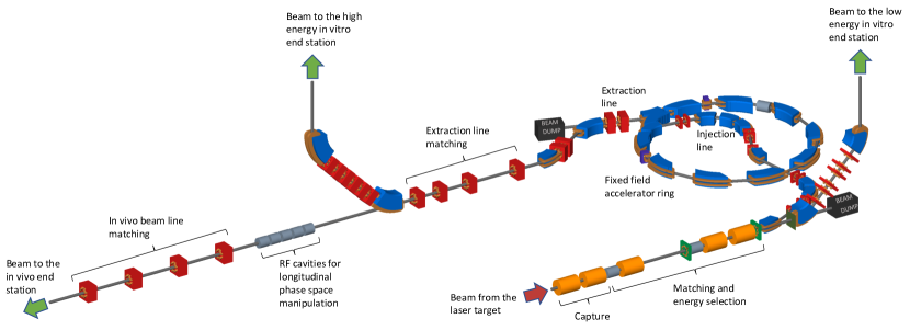
The LhARA facility, shown schematically in figure 1, has been designed to serve two end stations for in vitro radiobiology and one end station for in vivo studies. The principle components of the LhARA accelerator are: the laser-driven proton and ion source; the matching and energy selection section; beam delivery to the low-energy in vitro end station; the low-energy abort line; the injection line for the fixed-field alternating-gradient accelerator (FFA); the FFA; the extraction line; the high-energy abort line; beam delivery to the high-energy in vitro end station; and the transfer line to the in vivo end station. Proton beams with energies of between 12 MeV and 15 MeV will be delivered directly from the laser-driven source to the low-energy in vitro end station via a transfer line. The high-energy in vitro end station and the in vivo end station will be served by proton beams with energy between 15 MeV and 127 MeV and by ion beams, including C6+ with energies up to 33.4 MeV/u. This configuration makes it natural to propose that LhARA be constructed in two stages; Stage 1 providing beam to the low-energy in vitro end station and Stage 2 delivering the full functionality of the facility. The development of LhARA Stage 1 will include machine performance and optimisation studies designed to allow in vitro experiments to begin as soon as possible.
The design parameters for the various components of LhARA are given in tables 1 and 2. The design of the LhARA facility is described in the sections that follow.
| Parameter | Value or range | Unit |
| Laser driven proton and ion source | ||
| Laser power | 100 | TW |
| Laser Energy | 2.5 | J |
| Laser pulse length | 25 | fs |
| Laser rep. rate | 10 | Hz |
| Required maximum proton energy | 15 | MeV |
| Proton and ion capture | ||
| Beam divergence to be captured | 50 | mrad |
| Gabor lens effective length | 0.857 | m |
| Gabor lens length (end-flange to end-flange) | 1.157 | m |
| Gabor lens cathode radius | 0.0365 | m |
| Gabor lens maximum voltage | 65 | kV |
| Number of Gabor lenses | 2 | |
| Alternative technology: solenoid length | 1.157 | m |
| Alternative technology: solenoid max field strength | 1.3 | T |
| Stage 1 beam transport: matching & energy selection, beam delivery to low-energy end station | ||
| Number of Gabor lenses | 3 | |
| Number of re–bunching cavities | 2 | |
| Number of collimators for energy selection | 1 | |
| Arc bending angle | 90 | Degrees |
| Number of bending magnets | 2 | |
| Number of quadrupoles in the arc | 6 | |
| Alternative technology: solenoid length | 1.157 | m |
| a Alternative technology: solenoid max field strength (to serve the injection line to the Stage 2) | 0.8 (1.4) | T |
| Parameter | Value or range | Unit |
| Stage 2 beam transport: FFA, transfer line, beam delivery to high-energy end stations | ||
| Number of bending magnets in the injection line | 7 | |
| Number of quadrupoles in the injection line | 10 | |
| FFA: Machine type | single spiral scaling FFA | |
| FFA: Extraction energy | 15–127 | MeV |
| FFA: Number of cells | 10 | |
| FFA: Orbit Rmin | 2.92 | m |
| FFA: Orbit Rmax | 3.48 | m |
| FFA: Orbit excursion | 0.56 | m |
| FFA: External R | 4 | m |
| FFA: Number of RF cavities | 2 | |
| FFA: RF frequency | 1.46–6.48 | MHz |
| FFA: harmonic number | 1, 2 or 4 | |
| FFA: RF voltage (for 2 cavities) | 4 | kV |
| FFA: spiral angle | 48.7 | Degrees |
| FFA: Max B field | 1.4 | T |
| FFA: k | 5.33 | |
| FFA: Magnet packing factor | 0.34 | |
| FFA: Magnet opening angle | 12.24 | degrees |
| FFA: Magnet gap | 0.047 | m |
| FFA: Ring tune (x,y) | (2.83,1.22) | |
| FFA: | 2.516 | |
| FFA: Number of kickers | 2 | |
| FFA: Number of septa | 2 | |
| Number of bending magnets in the extraction line | 2 | |
| Number of quadrupoles in the extraction line | 8 | |
| Vertical arc bending angle | 90 | Degrees |
| Number of bending magnets in the vertical arc | 2 | |
| Number of quadrupoles in the vertical arc | 6 | |
| Number of cavities for longitudinal phase space manipulation | 5 | |
| Number of quadrupoles in the in vivo beam line | 4 | |
| In vitro biological end stations | ||
| Maximum input beam diameter | 1-3 | cm |
| Beam energy spread (full width) | Low-energy end station: | % |
| High-energy end station: | % | |
| Input beam uniformity | % | |
| Scintillating fibre layer thickness | 0.25 | mm |
| Air gap length | 5 | mm |
| Cell culture plate thickness | 1.3 | mm |
| Cell layer thickness | 0.03 | mm |
| Number of end stations | 2 | |
| In vivo biological end station | ||
| Maximum input beam diameter | 1-3 | cm |
| Beam energy spread (full width) | % | |
| Input beam uniformity | % | |
| Beam options | Spot-scanning, passive scattering, micro-beam | |
3.1 Laser-driven proton and ion source
Laser-driven ions have been posited as a source for radiobiological studies for a number of years [27, 41, 42]. Until now, the achievable ion energies, energy spreads, and reproducibility of such beams have meant that such sources are not suitable for a full radiobiological laboratory setting. While a number of cell irradiation experiments have been conducted with laser-accelerated ions [29, 30, 43, 36], these have been limited in scope to a single-shot configuration. In addition, most of these experiments have been performed on high-power laser facilities with rapidly shifting priorities, where the time to install dedicated diagnostic systems has not been available. At present, a dedicated ion beam for radiobiology, based on a laser-driven source, is not available anywhere in the world. Therefore, LhARA will be a unique, state-of-the-art system, able to explore the radiobiological benefits of a laser-accelerated ion source.
A novel solution for ion-acceleration is to use a compact, flexible laser-driven source coupled to a state-of-the-art beam-transport line. This allows an accelerating gradient of GV/m to be exploited at the laser-driven source. We propose to operate in a laser-driven sheath-acceleration regime [44, 45, 46] for ion generation. An intense, short laser pulse will be focused onto a target. The intense electric field generated on the front surface of the target accelerates the surface electrons, driving them into the material. Electrons which gain sufficient energy traverse the target, ionising the material as they go. A strong space-charge electric field, the ‘sheath’, is created as the accelerated electrons exit the rear surface of the target. This field in turn accelerates surface-contaminant ions. The sheath-acceleration scheme has been shown to produce ion energies greater than 40 MeV/u at the highest laser intensities. The maximum proton energy () scales with laser intensity () as, . The laser required to deliver a significant proton flux at 15 MeV can be compact, relatively inexpensive, and is commercially available.
The distribution of proton and ion energies observed in laser-driven beams exhibits a sharp cut off at the maximum energy and, historically, the flux of laser-accelerated ion beams has varied significantly shot-to-shot. To reduce the impact of the shot-to-shot variations the choice has been made to select particles from the plateau of the two-temperature energy spectrum of the laser-accelerated ion beam. This choice should enhance ion-beam stability and allow reproducible measurements to be carried out at ultra-high dose rates using a small number of fractions. To create the flux required in the plateau region it is proposed that a 100 TW laser system is used. A number of commercial lasers are available that are capable of delivering J in pulses of duration fs, at 10 Hz with contrast better than . Shot-to-shot stability of % is promised, an important feature for stable ion-beam production.
Key to the operation of this configuration is a system that refreshes the target material at high-repetition rate in a reproducible manner. A number of schemes have been proposed for such studies, from high-pressure gases [47, 48, 49], cryogenic hydrogen ribbons [50, 51, 52], liquid sheets [53] and tape drives [54]. For the LhARA facility, a tape drive based on the system developed at Imperial College London is proposed. This system is capable of reliable operation at target thicknesses down to 5 m, using both aluminium and steel foils, and down to 18 m using plastic tapes. Such tape-drive targets allow operation at high charge (up to pC at MeV, i.e. protons per shot) and of delivering high-quality proton and ion fluxes at repetition rates of up to 10 Hz or greater.
The unique features of the laser-driven ion source proposed for LhARA offer a number of opportunities to push the frontiers in the fields of sustained high-frequency ion generation, advanced targetry solutions and active, high-repetition rate diagnostics. The successful development and execution of LhARA will provide a leap forward in terms of capability and open up exciting new opportunities for applications not just in radiobiology. While pushing these new frontiers, the radiobiological-capabilities of LhARA are based on relatively low-energy ion beams, mitigating the risks that operating at the energy-frontier of the field would imply.
High repetition-rate operation of laser-driven radiation sources is a relatively new area of interest [54, 55, 56, 57, 58]. Such operating schemes pose a number of engineering challenges. It is proposed to apply machine-learning and genetic algorithms to the optimisation of the laser-target interaction to optimise the beam charge, peak energy, energy spread, and divergence of the ion flux produced [55]. These techniques will require appropriate R&D effort. The first experiments of this kind will be possible using the existing laser capabilities at Imperial College London, the Central Laser Facility at the Rutherford Appleton Laboratory, and elsewhere.
The careful control of the tension on the tape in a tape-drive target is critical for reproducible operation. The tape must be stretched to flatten the surface, without stretching it to its plastic response. Surface flatness is important for a number of reasons. Rippling of the front surface modifies the laser absorption dramatically; uncharacterised rippling can make shot-to-shot variations significant and unpredictable [54]. Similarly, rear surface perturbations can modify the sheath field, resulting in spatial non-uniformities of the proton beam or suppression of the achievable peak energies. Tape drives with torsion control and monitoring to maintain a high-quality tape surface have been designed and operated in experiments at Imperial College London. The development of these targets continues with a view to the production of new, thinner tapes for improved ion generation and the creation of ion species other than proton and carbon. This is an active area of R&D that will continue with the development of LhARA.
High repetition-rate ion-beam diagnostics will also need to be developed. Such diagnostics will need to measure both the energy spectrum and the spatial profile of the beams. Current methods are destructive and are often limited to low-repetition rate. Passive detectors have not been demonstrated in the conditions that will pertain at LhARA. Technologies being evaluated to address the issues raised by ion-source diagnostics for LhARA are discussed in section 3.5.
3.2 Proton and ion capture
The use of an electron cloud as a focusing element for charged-particle beams was first proposed by Gabor in 1947 [59]. Gabor noted that a cloud of electrons uniformly distributed about the axis of a cylindrical vessel would produce an ideal focusing force on a beam of positively charged particles. The focal length of such a lens scales with the energy of the incoming particle beam allowing such lenses to provide strong focussing of high-energy beams. Confinement conditions in the radial and axial directions can be determined [60]. In the radial direction, where there is magnetic confinement and Brillouin flow, the number density of electrons, , that can be contained is given by:
| (1) |
where is the magnetic field, the mass of the electron, and the permittivity of free space. In the longitudinal direction there is electrostatic confinement for which is given by:
| (2) |
where the magnitude of the charge on the electron and is the radius of the cylindrical anode which is held at the positive potential . For the electron densities of interest for LhARA the required anode voltage is of the order of 50 kV.
In the thin lens approximation, the focal length, , of a Gabor lens can be expressed in terms of the magnetic field and the particle velocity, [61]:
| (3) |
where is the mass of the particles in the beam. The focal length of the Gabor lens is therefore proportional to the kinetic energy or, equivalently, the square of the momentum, of the incoming beam. By comparison, the focal length for a solenoid is proportional to the square of the momentum and that of a quadrupole is proportional to momentum. At the particle energies relevant to LhARA the Gabor lens, or the solenoid, is therefore preferred.
An expression for the focal length as a function of electron number density can be derived by substituting equation (1) into equation (3) to give:
| (4) |
where is the kinetic energy of the particle beam. The focal length of the Gabor lens is inversely proportional to the number density of electrons trapped in the cloud. The focal lengths desired to capture the proton and ion beams at LhARA have been chosen such that the required electron number densities are conservative and lie within the range covered in published experiments.
For a given focal length, the magnetic field required in the Gabor lens is reduced compared to that of a solenoid that would give equivalent focusing. In the non-relativistic approximation the relationship between the magnetic field in the Gabor lens, , and the equivalent solenoid, , is given by [60]:
| (5) |
where is the mass of the ions being focused, and is the charge state of the ions. In the case of a proton beam the reduction factor is 43. Thus, for example, where a 2 T superconducting solenoid would be required, the magnetic field required for a Gabor lens would only be 47 mT. This means the cost of the solenoid for a Gabor lens can be significantly lower than the cost for a solenoid of equivalent focusing strength.
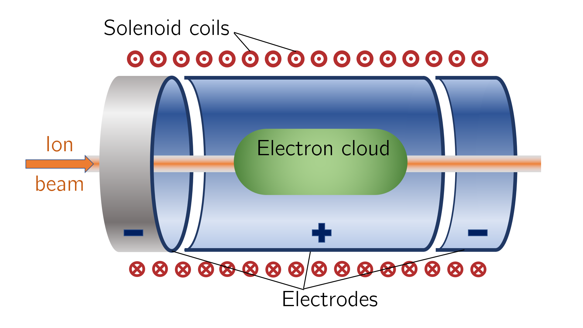
The plasma-confinement system described above is commonly known as a ‘Penning trap’ and has found wide application in many fields [62]. Variations on the Penning trap where axial apertures in the cathodes are introduced, such as the Penning-Malmberg trap [63, 64] are attractive for beam-based applications due to the excellent access provided to the plasma column, see figure 2.
Instability of the electron cloud is a concern in the experimental operation of Gabor lens; azimuthal beam disruption due to the diocotron instability has been observed and described theoretically [65]. Theory indicates that the diocotron instability is most problematic under well-defined geometric conditions. The reliable operation of a Gabor lens in a regime free from this instability has yet to be demonstrated. Gabor lenses promise very strong focusing, simple construction, and low magnetic field, all attractive features for LhARA. However, these attractive features come at the cost of relatively high voltage operation ( kV) and possible vulnerability to instability.
With reliable operation of Gabor lenses as yet unproven, we plan a two-part experimental and theoretical programme of research to prove Gabor-lens suitability. Initial work will include: theoretical investigation of lens stability in a full 3D particle-in-cell code such as VSIM [66]; and the development of electron-density diagnostics based on interferometric measurement of the refractive-index change. These activities will be applied to a time-invariant electron cloud. A test Gabor lens will be constructed to allow validation of both the simulation results and a new diagnostic using an alpha emitter as a proxy for the LhARA beam. In addition, the initial investigation will include the design of an electron beam to fill the lens. This last objective will enable the second part of the experimental project; the operation of the Gabor lens in short pulses. It is attractive to match the timing of the establishment of the electron cloud within the Gabor lens to that of the beam and thereby limit instability growth. The research project is time limited such that, should it not prove possible to produce a suitable Gabor lens, there will remain time sufficient to procure conventional solenoids in their place.
3.3 Beam transport and delivery to the low-energy in vitro end station
Beam-transport from the laser-driven ion source and delivery to the low-energy in vitro end station is required to deliver a uniform dose distribution at the cell layer. Beam losses must be minimised for radiation safety and to maximise the dose that can be delivered in a single shot. The transport line has been designed to minimise regions in which the beam is brought to a focus to reduce the impact of space-charge forces on the beam phase-space. An optical solution was initially developed using Beamoptics [67] and MADX [68]. Accurate estimation of the performance of the beam line requires the inclusion of space-charge forces and particle-matter interactions. Therefore, performance estimation was performed using Monte Carlo particle-tracking from the ion source to the end station. BDSIM [69], which is based on the Geant4 toolkit was used for the simulation of energy deposition arising from beam interactions with the material in the accelerator and the end station. GPT [70] was used for evaluating the full 3D impact of space-charge.
An idealised Gaussian beam was generated with a spot size of 4 m FWHM, an angular divergence of 50 mrad, 35 fs FWHM bunch length, and an energy spread of MeV. The maximum estimated bunch charge is protons. The presence of a substantial electron flux produced from the laser target compensates the high proton charge density in the vicinity of the ion-production point. Therefore, the first 5 cm of beam propagation was simulated without space-charge. Beyond this, the proton beam will have separated from the lower energy electrons sufficiently for space-charge to become a prominent effect and cause an emittance growth. Therefore, a further 5 cm drift was simulated including space-charge forces. At a distance of 10 cm from the ion source the beam is at the exit of the laser-target vessel. The kinematic distributions of ions in the beam were stored at this point and passed to the relevant BDSIM and GPT simulations of the downstream beam line.
The beam line, shown schematically in figure 3, is composed of five sections: beam capture; matching and energy selection; beam shaping; vertical arc matching; and an abort line. The capture section uses two Gabor lenses to minimise the transverse momentum of particles in the beam. Beyond the capture section, an RF cavity permits control of the bunch length and manipulation of the longitudinal phase-space. A third Gabor lens then focuses the bunch to a small spot size after which a second RF cavity is located to provide further longitudinal phase-space manipulation. Two further Gabor lenses bring the beam parallel once more in preparation for the vertical 90∘ arc. All Gabor lenses have an inner radius of 3.65 cm and an effective length of 0.857 m. All lenses operate below the maximum cathode voltage of 65 kV.
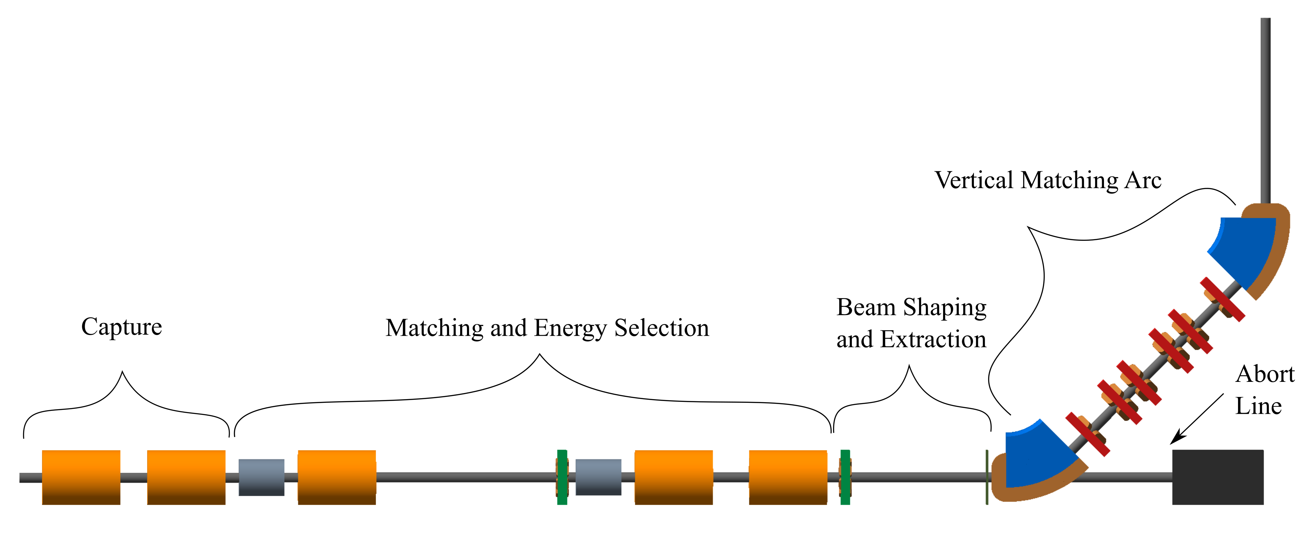
A parallel beam emerges from the final Gabor lens, providing significant flexibility for the inclusion of beam shaping and extraction systems. Beam uniformity will be achieved using octupole magnets to provide third-order focusing to perturb the first-order focusing from the Gabor lenses. Such schemes have been demonstrated in a number of facilities [71, 72, 73]. A suitable position for the first octupole was identified to be after the final Gabor lens where the beam is large; its effect on the beam is expected to be significant. Octupoles were only modelled in BDSIM as GPT does not have a standard component with an octupolar field. The typical rectangular transverse distribution resulting from octupolar focusing requires collimation to match the circular aperture through which the beam enters the end station. A collimator is therefore positioned at the start of the vertical arc. Further simulations are required to determine the optimum position of the second octupole and to evaluate the performance of the octopoles. The switching dipole which directs the beam to the injection line of the FFA in Stage 2 will be located between the second octupole and the collimator, requiring the octupole to be ramped down for Stage 2 operation.
The vertical arc uses transparent optics in an achromat matching section to ensure that the first-order transfer map through the arc is equivalent to the identity transformation and that any dispersive effects are cancelled. A 2 m drift tube is added after the arc to penetrate the concrete shielding of the end station floor and to bring the beam to bench height. The abort line consists of a drift followed by a beam dump and requires the first vertical dipole to ramp down, preventing charged-particle transportation to the end station.
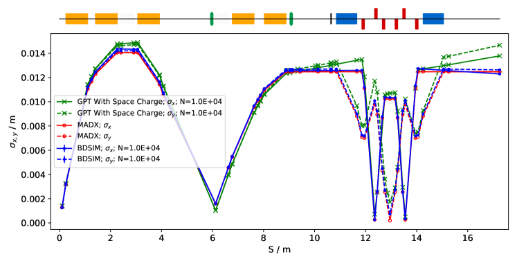
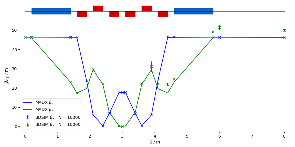
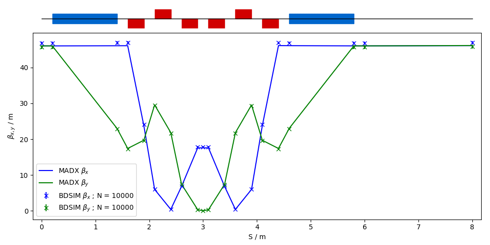
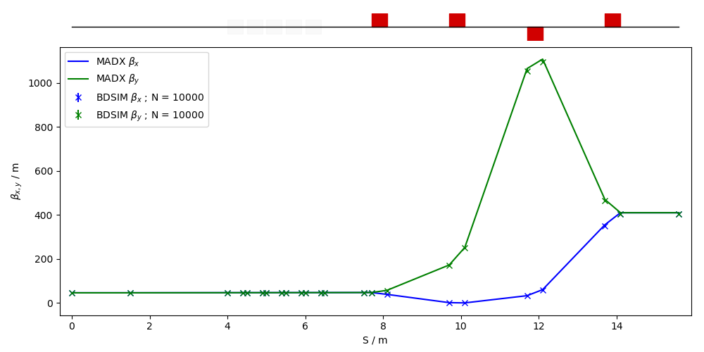
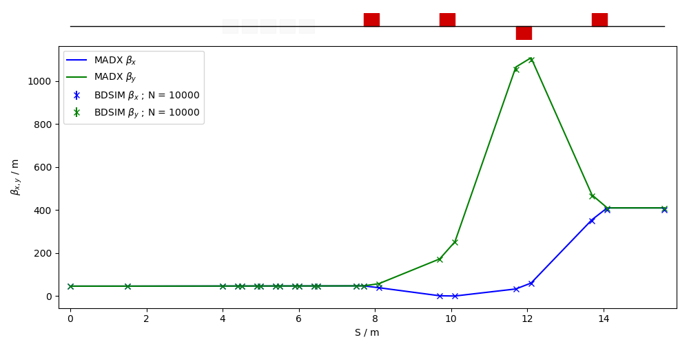
The underlying physics of plasma-lens operation cannot be simulated in BDSIM or GPT, however it can be approximated using solenoid magnets of equivalent strength. RF cavity fields were not simulated. 10 000 particles were simulated corresponding to the estimated maximum bunch charge of protons. Figure 4 shows excellent agreement between horizontal and vertical transverse beam sizes in BDSIM and MADX, verifying the beam line’s performance in the absence of space-charge effects. Reasonable agreement between BDSIM and GPT is also seen when space-charge forces are included in GPT. Emittance growth is observed prior to the first solenoid, affecting the optical parameters throughout the machine. However, the resulting beam dimensions at the cell layer of 1.38 cm horizontally and 1.47 cm vertically are not significantly different from the ideal beam in BDSIM. Further adjustments of the Gabor lenses and arc-quadrupole strengths may compensate for this. The transmission efficiency of the beam line is approximately 100%.
The small bunch dimensions in both transverse planes at the focus after the third Gabor lens, where the energy selection collimator will be placed, remains a concern if the effect of space-charge has been underestimated. Similar bunch dimensions are achieved in the vertical arc, however, quadrupolar focusing is confined to a single plane mitigating further emittance growth. Further tuning of the Gabor lens voltages in the capture section may compensate space-charge effects, reducing the non-zero transverse momentum seen entering the vertical arc.
To investigate beam uniformity, BDSIM simulations with and without octupoles and collimation for beam shaping were conducted. Both octupoles were arbitrarily set to a strength of with a magnetic length of 0.1 m and pole-tip radius of 5 cm, which, for a 15 MeV beam corresponds to pole-tip field of 0.42 T. A 2 cm thick iron collimator with a 40 mm diameter aperture was positioned 1.5 m downstream of the octupole. Figure 5 shows the beam phase-space and particle distributions at the end station for the transverse and longitudinal axes with and without beam shaping. Without octupoles the spatial profile is Gaussian as expected, however, beam uniformity is improved with octupoles and collimation. The total beam width is 3.58 cm horizontally and 3.46 cm vertically which is sufficient to irradiate one well in a six-well cell-culture plate. Further optimisation is required to improve uniformity whilst optimising beam-line transmission, which is approximately 70% for the results presented in figure 5. An aberration can be seen in both transverse planes with and without beam shaping; this effect originates upstream of the octupoles in the solenoids, and persists through to the end station. These aberrations are a concern, however, future simulation efforts will replace the solenoids with a full electromagnetic simulation of the Gabor lens. This change is likely to change the aberrations. The non-Gaussian energy distribution without beam shaping is a result of space-charge forces at the ion source; the distribution persists to the end station as no components which affect the longitudinal phase space were simulated. The Gaussian distribution seen with beam shaping is due to collimation.
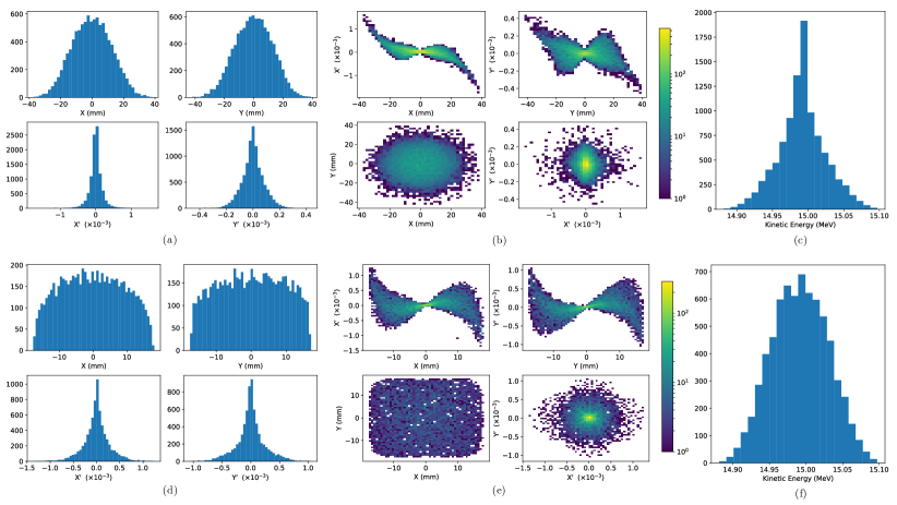
The proposed design is capable of delivering beams of the desired size
to the in vitro end station.
Space-charge effects impact the beam-transport performance but it is
believed that this can be mitigated with minor adjustments to the
Gabor lenses in the capture section.
Initial studies indicate that a uniform beam can be delivered with
further optimisation of the octupoles and collimator.
3.3.1 Alternative Design
To mitigate potential emittance growth from space-charge forces, an alternative beam line design was developed in which the final two Gabor lenses in the matching and energy selection section are replaced by four quadrupoles, limiting any bunch focusing to one plane at a time. The resulting machine is reduced in length to 15.439 m. Without space-charge effects, a beam sigma of 2.5 mm at the end station can be achieved. With space-charge, emittance growth prior to the first solenoid is once again observed leading to an increased beam size at the entrance of the first quadrupole, resulting in a spatially asymmetric and divergent beam at the end station. It is believed that the space-charge effects can be compensated by applying the same Gabor-lens optimisation as in the baseline design and adjusting the quadrupole settings to deliver beam parameters similar to those without achieved in the absence of space charge. The alternative design provides a solution that is more resilient to space-charge effects than the baseline, however, only the lower bound on the desired beam size has been achieved so far. Further optimisation is required not only to optimise optical performance but also to optimise octupole settings and to determine whether a beam with the desired uniformity can be delivered to the end station.
3.4 Post-acceleration and beam delivery to the in vitro and in vivo end stations
A fixed-field alternating-gradient accelerator (FFA), based on the spiral scaling principle [74, 75, 76, 77], will be used to accelerate the beam in LhARA Stage 2 to obtain energies greater than the 15 MeV protons and 4 MeV/u carbon (C6+) ions delivered by the laser-driven source. FFAs have many advantages for both medical and radiobiological applications such as: the capability to deliver high and variable dose; rapid cycling with repetition rates ranging from 10 Hz to 100 Hz or beyond; and the ability to deliver various beam energies without the use of energy degraders. An FFA is relatively compact due to the use of combined function magnets, which lowers the overall cost compared to conventional accelerators capable of delivering beams at a variety of energies such as synchrotrons. Extraction can be both simple and efficient and it is possible for multiple extraction ports to be provided. Furthermore, FFAs can accelerate multiple ion species, which is very important for radiobiological experiments and typically very difficult to achieve with cyclotrons.
A typical FFA is able to increase the beam momentum by a factor of three, though a greater factor may be achieved. For LhARA, this translates to a maximum proton-beam energy of 127 MeV from an injected beam of 15 MeV. For carbon ions (C6+) with the same rigidity, a maximum energy of approximately 33.4 MeV/u can be produced.
The energy at injection into the FFA determines the beam energy at extraction. The injection energy will be changed by varying the focusing strengths in the Stage 1 beam line from the capture section through to the extraction line and the FFA ring. This will allow the appropriate energy slice from the broad energy spectrum produced at the laser-driven source to be captured and transported to the FFA. The FFA will then accelerate the beam, acting as a three-fold momentum multiplier. This scheme simplifies the injection and extraction systems since their geometry and location can be kept constant.
A second, ‘high-energy’, in vitro end station will be served by proton beams with a kinetic energy in the range 15–127 MeV and carbon-ion beams with energies up to 33.4 MeV/u. The extraction line from the FFA leads to a 90∘ vertical arc to send the beam to the high-energy in vitro end station. If the first dipole of the arc is not energised, beam will be sent to the in vivo end station. The extraction line of the FFA includes a switching dipole that will send the beam to the high-energy-beam dump if it is not energised. The detailed design of the high-energy abort line, taking into account the requirement that stray radiation does not enter the end stations, will be performed as part of the LhARA R&D programme.
3.4.1 Injection line
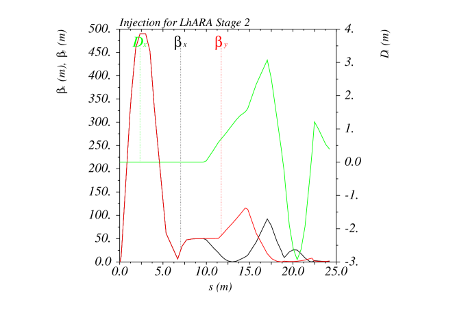
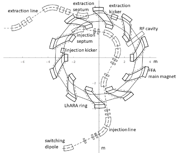
The settings of the Stage 1 beam line need to be adjusted to reduce the Twiss function propagating through the injection line to allow beam to be injected into the FFA ring. The optical parameters in the Stage 1 beam line after adjustment are shown in figure 6. The beam is diverted by a switching dipole into the injection line which transports the beam to the injection septum magnet. The injection line matches the Twiss functions in both transverse planes and the dispersion of the beam to the values dictated by the periodic conditions in the FFA cell (figure 6). The presence of dispersion in the injection line allows a collimator to be installed for momentum selection before injection. The beam is injected from the inside of the ring, which requires the injection line to cross one of the straight sections between the FFA magnets, see figure 7.
3.4.2 FFA ring
The magnetic field, , in the median plane of a scaling spiral FFA is given by [74, 75, 76]:
| (6) |
where is the magnetic field at radius , is the field index, corresponds to the spiral angle and is the ‘flutter function’. This field law defines a zero-chromaticity condition, which means the working point of the machine is independent of energy up to field errors and alignment imperfections. This avoids crossing any resonances, which would reduce the beam quality and may lead to beam loss.
Table 2 gives the main design parameters of the FFA ring. The ring consists of ten symmetric cells each containing a single combined-function spiral magnet. The choice of the number of cells is a compromise between the size of the orbit excursion, which dictates the radial extent of the magnet, and the length of the straight sections required to accommodate the injection and extraction systems.
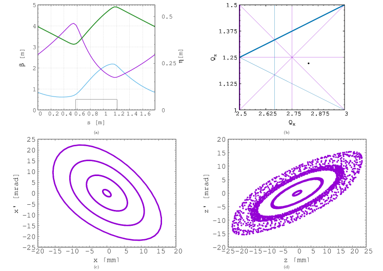
The betatron functions and dispersion in one lattice cell at injection are shown in figure 8a. The tune diagram, showing the position of the working point of the machine in relation to the main resonance lines, is shown in figure 8b. Tracking studies were performed using a step-wise tracking code in which the magnetic field is integrated using a Runge-Kutta algorithm [78]. The magnetic field in the median plane was obtained using the ideal scaling law (equation 6) and using using Enge functions to give the fringe fields. The field out of the median plane was obtained using Maxwell’s equations and a -order Taylor expansion of the field. The dynamic acceptance for 100 turns, shown for the horizontal and vertical planes in figures 8c and 8d respectively, are significantly larger than the beam emittance. This statement holds even when the most pessimistic scenario, in which the emittance is assumed to be ten times larger than nominal, is used. These results confirm that a good machine working point has been chosen.
A full aperture, fast injection of the beam will be performed using a magnetic septum, installed on the inside of the ring, followed by a kicker magnet situated in a consecutive lattice cell, as shown in figure 7. The specifications of the injection system are dictated by the parameters of the beam at injection, which are summarised for the nominal proton beam in table 3. The beam at injection has a relatively small emittance and short bunch length, which limits the intensity accepted by the ring due to the space-charge effect. An intensity of approximately protons will be accepted by the ring assuming the nominal beam parameters. Space-charge effects will be severe immediately after injection, but will quickly be reduced due to the debunching of the beam. Fast extraction of the beam over the full aperture will be performed using a kicker magnet followed by a magnetic septum installed in a consecutive lattice cell close to the extraction orbit.
| Parameter | Unit | Value |
|---|---|---|
| Beam energy | MeV | 15 |
| Total relative energy spread | % | |
| Nominal physical RMS emittance (both planes) | m rad | |
| Incoherent space charge tune shift | -0.8 | |
| Bunching factor | 0.023 | |
| Total bunch length | ns | 8.1 |
| Bunch intensity |
Acceleration of the beam to 127 MeV will be done using an RF system operating at harmonic number with an RF frequency range from 2.89 MHz to 6.48 MHz. The RF voltage required for 10 Hz operation is 0.5 kV. However, at such a low voltage the energy acceptance at injection will be limited to % so a voltage of 4 kV is required to increase the energy acceptance to %. This voltage can be achieved with one cavity [79], two cavities are assumed to provide greater operational stability. Normal conducting spiral-scaling FFA magnets, similar to the ones needed for LhARA, have been constructed successfully [77, 80] using either distributed, individually-powered coils on a flat pole piece or using a conventional gap-shaping technique. For the LhARA FFA, we propose a variation of the coil-dominated design recently proposed at the Rutherford Appleton Laboratory in R&D studies for the upgrade of the ISIS neutron and muon source. In this case, the nominal scaling field is achieved using a distribution of single-powered windings on a flat pole piece. The parameter can then be tuned using up to three additional independently-powered windings. The extent of the fringe field across the radius of the magnet must be carefully controlled using a ‘field clamp’ to achieve zero-chromaticity. An active clamp, in which additional windings are placed around one end of the magnet, may be used to control the flutter function and thereby vary independently the vertical tune of the FFA ring. The FFA is required to deliver beams over a range of energy; each energy requiring a particular setting for the ring magnets. Therefore, a laminated magnet design may be required to reduce the time required to change the field. The magnet gap of 4.7 cm given in table 2 is estimated assuming a flat-pole design for the magnet. The details of the design will be addressed in as part of the LhARA R&D programme.
3.4.3 Extraction Line
Substantial margins in the beam parameters were assumed in the design of the extraction line from the FFA due to uncertainties in the beam distributions originating from: the Stage 1 beam transport; the FFA injection line; and potential distortions introduced by the presence of space-charge effects during acceleration in the ring. Therefore, the beam emittance was allowed, pessimistically, to be as large as a factor of ten greater than in the nominal value, which was derived assuming that the normalised emittance is conserved from the source, through the Stage 1 beam line, and in the FFA ring. In the nominal case, the physical emittance of the beam is affected by adiabatic damping only. Substantial flexibility in the optics of the extraction line is required, as the extraction line must accommodate a wide spectrum of beam conditions to serve the in vitro and in vivo end-stations.
Detailed studies were carried out for proton beams with kinetic energies of 40 MeV and 127 MeV. Table 4 gives the Twiss values for different beam sizes for the 40 MeV and 127 MeV proton-beam scenarios assuming a Gaussian beam distribution. The optics and geometric acceptance of the system is approximately the same for the 40 MeV and 127 MeV beams. This justified the working hypothesis that beam emittance is approximately the same for both beam energies. This assumption will be revised as soon as space-charge simulations for the entire system are available.
| 40 MeV protons | 127 MeV protons | 127 MeV protons | |
| (Nominal) | (Nominal) | (Pessimistic) | |
| RMS Emittance (, ) [ mm mrad] | 0.137 | 0.137 | 1.37 |
| [m] for a 1 mm spot size | 0.46 | 0.46 | 0.039 |
| [m] for a 10 mm spot size | 46 | 46 | 4.5 |
| [m] for a 30 mm spot size | 410 | 410 | 40 |
The first two dipoles and four quadrupoles of the extraction line bend the beam coming from the extraction septum of the FFA such that it is parallel to the low-energy beam line while ensuring that dispersion is closed. Closing the dispersion is critical as off-momentum particles will follow trajectories different to those followed by particles with the design momentum and therefore impact the size and shape of the beam downstream. The second part of the extraction line consists of four quadrupoles which transport the beam either to the first dipole of the vertical arc that serves the high-energy in vitro end station or to the in vivo end-station if this dipole is not energised. These quadrupoles provide the flexibility required to produce the different beam sizes for the in vitro end station as specified in table 4.
3.4.4 High-energy in vitro beam line
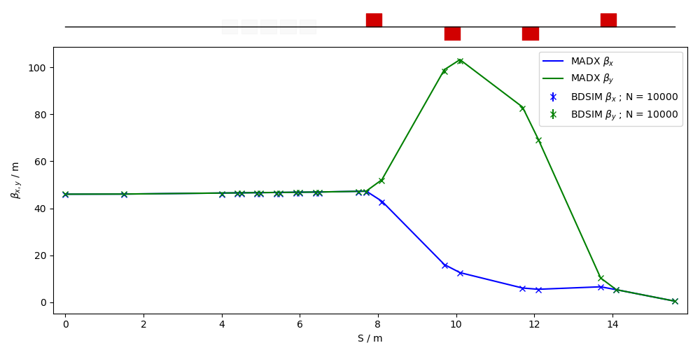
The high-energy in vitro beam line transports the beam from the exit of the extraction line and delivers it to the high-energy in vitro end station. The 90∘ vertical bend is a scaled version of the low-energy vertical arc, following the same design principles, and also consists of two bending dipole magnets and six quadrupole magnets. To accommodate the higher beam energies, the lengths of the magnets were scaled in order to ensure that peak magnetic fields were below the saturation limits of normal conducting magnets. The bending dipole magnet lengths were increased to 1.2 m each and the quadrupole lengths were tripled to 0.3 m each. The overall length of the arc then becomes 6 m, compared to 4.6 m for the low energy in vitro arc. This difference in arc length means the high-energy in vitro arc finishes about 0.9 m higher than the low-energy one. This difference can easily be accommodated by adjusting the final drift lengths.
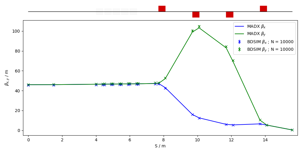
The quadrupole strengths for the scaled high-energy in vitro arc were
obtained using MAD-X and tracking simulations using BDSIM show good
agreement, see figure 9.
The input beam distribution used in BDSIM was assumed to be Gaussian
with Twiss , which gives a beam size of about 10 mm.
GPT simulations were performed which show small discrepancies due to
space-charge effects.
It may be possible to compensate for this by adjusting the strengths
of the quadrupoles in the arc and the matching section in the
extraction line.
3.4.5 In vivo beam line
If the first dipole of the high-energy in vitro arc is not energised then beam is sent to the in vivo end station. From the end of the extraction line, 7.7 m of drift is necessary to clear the first bending dipole of the in vitro arc, to provide space for the five RF cavities needed for longitudinal phase-space manipulation and to allow space for diagnostic devices. Following this drift is a further 6.6 m of beam line that includes four quadrupoles, each of length 0.4 m, which are used to perform the final focusing adjustments of the beam delivered to the in vivo end station. A final 1.5 m drift at the end is reserved for scanning magnets to be installed to perform spot scanning and to penetrate the shielding of the in vivo end station. In total the in vivo beam line is 15.6 m in length.
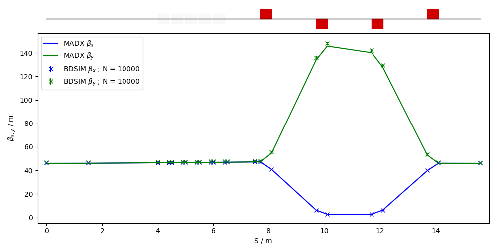
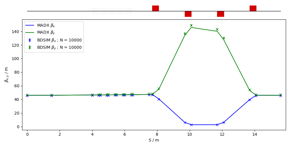
The design is flexible in matching the various values given in table 4, but is not able to match the smallest target value of m for the pessimistic scenario, which is very challenging. To verify that the optics design could provide the required beam sizes, simulations were performed with BDSIM using an input Gaussian beam generated with the Twiss values given in tables 4. Figure 10 shows the results of simulations for a 40 MeV proton beam and a nominal emittance 127 MeV proton beam matched in order to obtain beam sizes of 1 mm, 10 mm and 30 mm. GPT was used to investigate the effects of space-charge. These simulations show discrepancies compared to the BDSIM simulations. These discrepancies can be compensated for by adjusting the strengths of the quadrupoles in the matching section in the extraction line.
3.5 Instrumentation
Commercial off-the-shelf (COTS) instrumentation will be used for
Stages 1 and 2 of LhARA wherever possible.
However, the characteristics of the beam (e.g. very high
charge-per-bunch, low-to-moderate energy) will require some custom
solutions to be developed.
The authors are developing two concepts, termed SciWire and
SmartPhantom, for the low- and high-energy in vitro end
stations respectively.
These detectors can also be used for beam diagnostics.
This new instrumentation may find application at other facilities.
Instrumentation for the detection of secondary particles arising from the
interaction of the beam with tissue is not discussed here but is an
important area that will be studied in the future.
3.5.1 SciWire
For the Stage 1 beam, the maximum proton energy is 15 MeV.
Shot-to-shot characterisation of the beam is essential and requires
the use of a very thin detector with a fast response.
The SciWire [81] is being developed to provide energy and intensity profile
measurements for low-energy ion beams. A single SciWire plane consists of two layers of 250 m
square-section scintillating fibres, with the fibre directions in the two
layers orthogonal to each other.
A series of back-to-back planes provides a homogeneous volume of scintillator.
If there are enough planes to stop the beam, the depth of penetration will
allow the beam energy to be inferred.
This is obviously a destructive measurement so it is envisaged that this type of measurement
would only be used when experiments are not running. A single plane, however, can be used for
2D beam-profile measurements at the same time that beam is delivered for experiments.
Detection of the light from SciWire fibres may be by CMOS camera, or
using photodiodes.
If the instrumentation is sufficiently fast, the SciWire can be used to
derive feedback signals for beam tuning.
3.5.2 SmartPhantom
To study in real time the dose profile of Stage 2 beams, the
SmartPhantom [82] is being developed.
This is a water-filled phantom, which is instrumented with planes of
scintillating fibres, by which to infer the dose distribution with
distance.
The detection elements of the SmartPhantom are 250 m diameter,
round scintillating fibres.
Each fibre station consist of two planes of fibres, in which the fibre
directions are orthogonal.
Five fibre stations are arranged in the phantom in front of the
cell-culture flask.
The fibres may be coupled to photodiodes, or a CMOS camera.
Simulations in GEANT4 are being used to develop analysis techniques by
which to predict the position of the Bragg peak shot-by-shot.
The beam profile and dose delivered can then be calculated in real
time.
The key emphasis is to be able to derive these parameters from
shot-by-shot data, and not purely from simulations.
3.5.3 Beam line Instrumentation
The instrumentation requirement begins with the Ti:Sapphire laser. The laser focal spot will be characterised using a camera-based system and high-speed wavefront measurements [83] from COTS vendors.
For the Stage 1 beam line, beam position monitors (BPMs) will be needed for beam steering. Because of the low beam energy, non-intercepting BPMs using capacitive pickup buttons will be used. Custom pickups will be needed to match the beam pipe geometry but COTS electronics are available. The beam current will be monitored near the end of each beam line, using integrating current toroids (ICT), backed up with the option of insertable multi-layer Faraday cups (MLFC) to give absolute beam current and energy measurements. Beam profiles could be measured by SEM grids on both Stage 1 and Stage 2 beam lines. For Stage 1, these monitors will be mounted on pneumatic actuators to avoid scattering. Each end station could be equipped with insertable “pepper-pot” emittance monitors and a transverse deflection cavity with fluorescent screen could be provided for bunch shape measurements.
The BPMs on the FFA will require pickup designs suitable for the unusual, wide and shallow, vacuum vessel. The FFA at the KURNS facility in Kyoto is of a similar layout [84] and uses a kicker and capacitive pickup to perform tune measurements in each transverse direction. A minimum of one BPM every second cell will be used in the FFA so that the beam orbit can be measured. BPMs will also be required close to the injection and extraction septa. The BPM system may be able to use COTS electronics, but the pickups will be based on the KURNS design of multiple electrodes arranged across the vacuum vessel width.
The DAQ needs to be able to store calibration data and apply corrections in real time. It is necessary to be able to find the beam centre from a profile, even when the profile may be non-Gaussian and possibly asymmetric. FPGAs can be used to perform fast fitting and pattern recognition of beam profiles. The instrumentation will be integrated with the accelerator control system to be able to provide fast feedback and adjustment of the beam parameters in real time.
3.6 Biological end stations
In order to deliver a successful radiobiological research programme, high-end and fully equipped in vitro and in vivo end-stations will be housed within the LhARA facility. The two in vitro end-stations (high and low energy) will contain vertically-delivered beam lines which will be used for the irradiation of 2D monolayer and 3D-cell systems (spheroids and patient-derived organoids) in culture. The beam line within the end-stations will be housed in sealed units that will be directly sourced with appropriate gases (carbon dioxide and nitrogen), allowing for the cells within culture plates to be incubated for a short time in stable conditions prior to and during irradiation. This will also enable the chamber to act, where necessary, as a hypoxia unit (0.1%–5% oxygen concentration). Furthermore, these sealed units will contain robotics to enable simple movement of the numerous cell culture plates housed within to be placed into and taken away from the beam.
The in vitro end-stations will be located within a research laboratory equipped with up-to-date and state-of-the-art facilities. This, coupled with two separate end-stations and multiple workspaces, will enable multiple groups of researchers to perform productive and high-quality biological research. The laboratory will include all the vital equipment for bench-top science, sample processing and analysis (e.g. refrigerated centrifuges and light/fluorescent microscopes), along with the equipment required for contaminant-free cell culture (e.g. humidified CO2 cell culture incubators, Class II biological safety cabinets), and for the storage of biological samples and specimens (e.g. C and C freezers and fridges). The laboratory will also house an X-ray irradiator (allowing direct RBE comparisons between conventional photon irradiation, and the proton and carbon ions delivered by the accelerator), hypoxia chamber (for long-term hypoxia studies), a robotic workstation (handling and processing of large sample numbers, assisting in high-throughput screening experiments), and an ultra-pure-water delivery system. These facilities will enable a myriad of biological end-points to be investigated in both normal- and tumour-cell models not only from routine clonogenic survival and growth assays, but will expand significantly on more complex end-points (e.g. inflammation, angiogenesis, senescence and autophagy) as these experiments are difficult to perform at current clinical research beams due to limited time and facilities.
The in vivo end-station will be served with high-energy proton and carbon ions capable of penetrating deeper into tissues allowing the irradiation of whole animals. The ability to perform in vivo pre-clinical studies is vital for the future effective translation of the research into human cancer patients where optimum treatment strategies and reduction of side-effects can be defined. The in vivo end-station will allow the irradiation of a number of small-animal models (e.g. xenograft mouse and rat models) which can further promote an examination of particular ions on the appropriate biological end-points (e.g. tumour growth and normal tissue responses). The end-station will contain a small-animal handling area which will allow for the anaesthetisation of animals prior to irradiation. To enable the irradiation of small target volumes with a high level of precision and accuracy, an image guidance system (e.g. computed tomography) will be available. The animals will subsequently be placed in temperature-controlled holder tubes enabling the correct positioning of the relevant irradiation area in front of the beam line. The beam size is sufficient to give flexibility in the different irradiation conditions, in particular through passive scattering, pencil-beam scanning, and micro-beam irradiation, to be investigated at both conventional and FLASH dose rates. It is envisaged that the animals will be taken off-site post-irradiation to a nearby animal-holding facility for a follow-up period where biological measurements will be conducted.
3.7 Infrastructure and integration
The LhARA facility will encompass two floors of roughly 42 m in length and 18 m wide. The ground floor will contain the laser, accelerator, and in vivo end station while the first floor will house the laboratory area and the two in vitro end stations. The entire facility will require radiation protection in the form of concrete shielding, which will delineate the facility into three principal areas: a radiation-controlled access area, a laser controlled access area, and a laboratory limited-access area.
It is envisaged that LhARA will be built at an STFC National Laboratory or equivalent research institute which has an established safety-management system and culture in place. At STFC, a comprehensive set of Safety Codes has been developed to cover the hazards associated with working in such an environment. STFC Safety Codes applicable to LhARA include: risk management, construction, biological safety, working with lasers, working with time-varying electro-magnetic fields, management of ionising radiation, and electrical safety. In practice at STFC, these codes are backed-up by the knowledge, skills and experience of staff, and by appointed responsible persons such as Radiation Protection Advisors, Laser Responsible Officers, and Authorising Engineers. In addition, STFC operates many facilities that encompass the same hazards as LhARA, which, for lasers, include the Gemini Target Areas 2 and 3 [85] as well as the new EPAC (Extreme Photonics Application Centre) [86] and for accelerators include FETS (Front End Test Stand) [87], and the ISIS Neutron and Muon Source [88]. Safety systems and equipment will be required for LhARA, which will include Class II biological safety cabinets for contaminant-free cell culture for in vitro radiobiological experiments.
For a facility such as LhARA, radiation safety is a primary concern and all work will be completed under Regulation 8 of the Ionising Radiations Regulations 2017 (IRR17) [89], which requires a radiation risk assessment before commencing a new work activity involving ionising radiation.
The infrastructure and integration of the LhARA facility will require R&D in four key areas: risk analysis (project risks), risk assessments (safety risks), radiation simulations, and controls development. The risk analysis will cover all aspects of the facility, such as funding and resource availability, not just technical risks. A safety-risk assessment will be performed to describe and control all potential safety risks in the facility. The safety-risk assessment will, to a reasonable degree, identify all pieces of equipment that require safety mitigations and identify control measures that must be put in place. Coupled closely with the safety-risk assessment, radiation simulations will be developed to characterise the radiation hazards in and around the LhARA facility. The last area to require R&D will be the control systems. It is expected that the facility will use the Experimental Physics and Industrial Control System (EPICS), which can be further developed at this stage.
4 Performance
The dose distributions delivered to the end stations were evaluated using BDSIM. Figure 11 shows the energy lost by the beam as it enters the low-energy in vitro end station. The beam passes through the vacuum window, a layer of scintillating fibre, and a 5 mm air gap. The beam then enters the cell-sample container, assumed to be polystyrene, which supports a 30 m thick layer of cells, modelled using the Geant4 material “G4_SKIN_ICRP” [90]. The transverse momentum of protons in the beam was assumed to be Gaussian distributed, with a lateral spread small enough for the beam to be fully contained within the required spot size of 3 cm. Figure 11 shows that a proton beam with 10 MeV kinetic energy does not reach the cell. The Bragg peak of a 12 MeV proton beam is located close to the cell layer, while a 15 MeV beam, the maximum energy specified for delivery to the low-energy in vitro end station, has a Bragg peak located beyond the cell layer. LhARA’s ability to deliver various energies will allow the investigation of radiobiological effects for irradiations using different parts of the Bragg peak, effectively varying the LET across the sample.
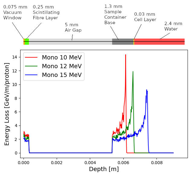
The maximum dose that can be delivered was evaluated for a variety of beam energies. The dose was estimated from simulations by calculating the energy deposited in a volume of water corresponding in size to the sensitive volume of a PTW 23343 Markus ion chamber [91] placed at the position of the Bragg peak in each case. The cylindrical chamber has a radius of 2.65 mm and a depth of 2 mm, giving a volume of about m3. The total energy deposited within the chamber was recorded and converted into dose in units of Gray.
For the low-energy in vitro end station the minimum spot size is specified to have a diameter of 10 mm, which is larger than the area of the chamber. A single shot of protons at 12 MeV with the minimum design spot size deposits J in the chamber volume, corresponding to a dose of Gy. For this simulation, the thickness of the sample container was reduced so that the Bragg peak could be positioned within the chamber volume. For the bunch length of ns the maximum instantaneous dose rate is Gy/s and the average dose rate is Gy/s assuming a repetition rate of 10 Hz. A single shot of protons at 15 MeV deposits J in the chamber volume corresponding to a dose of Gy. This gives an instantaneous dose rate of Gy/s and an average dose rate of Gy/s assuming the same bunch length and repetition rate as for the 12 MeV case.
For the high-energy in vitro end station a different setup was used for high energy proton beams. A similar design to the low-energy end station was used but with the air gap increased from 5 mm to 5 cm and a water phantom was placed at the end of the air gap instead of a cell culture plate. The water phantom used in the simulation was based upon the PTC T41023 water phantom [92]. In addition, the smaller minimum design beam size of 1 mm was used. A single shot of protons at 127 MeV deposits J in the chamber at the pristine Bragg peak depth corresponding to a dose of Gy, an instantaneous dose rate of Gy/s and an average dose rate of Gy/s. The end-station design assumed for a 33.4 MeV/u carbon beam was the same as that used for the low-energy in vitro end station due to the limited range in water of the carbon beam. The intensity of the beam is a factor of 12 less than for protons in order to preserve the same strength of the space-charge effect at injection into the FFA with the same beam parameters, as the incoherent space charge tune shift is proportional to and inversely proportional to , where corresponds to the particle charge, its mass number and , its relativistic parameters. A single pulse of ions, deposits J at the depth of the pristine Bragg peak, leading to an instantaneous dose rate of Gy/s and a maximum average dose rate of Gy/s.
The expected maximum dose rates are summarised in table 5. The instantaneous dose rates depend on the bunch length which differs depending on the energies. For the low-energy in vitro line a 7 ns bunch length is assumed here for all energies. While for the higher energies, a 127 MeV proton beam is delivered with a bunch length of 41.5 ns, and a bunch length of 75.2 ns for a 33.4 MeV/u carbon beam. The same repetition rate of 10 Hz was used for all energies. The minimum beam size at the start of the end station for the 12 MeV and 15 MeV proton-beam simulations was 1 cm. A 1 mm beam size was used for the 127 MeV proton beam and 33.4 MeV/u carbon-ion beam simulations.
| 12 MeV Protons | 15 MeV Protons | 127 MeV Protons | 33.4 MeV/u Carbon | |
|---|---|---|---|---|
| Dose per pulse | Gy | Gy | Gy | Gy |
| Instantaneous dose rate | Gy/s | Gy/s | Gy/s | Gy/s |
| Average dose rate | Gy/s | Gy/s | Gy/s | Gy/s |
5 Conclusions
The initial conceptual design of LhARA, the Laser-hybrid Accelerator for Radiobiological Applications, has been described and its performance evaluated in simulations that take into account the key features of the facility. LhARA combines a laser-driven source to create a large flux of protons or light ions which are captured and formed into a beam by strong-focusing plasma lenses thus evading the current space-charge limit on the instantaneous dose rate that can be delivered. Acceleration, performed using an fixed-field alternating-gradient accelerator, preserves the unique flexibility in the time, spectral, and spatial structure of the beam afforded by the laser-driven source. The ability to trigger the laser pulse that initiates the production of protons or ions at LhARA will allow the time structure of the beam to be varied to interrupt the chemical and biological pathways that determine the biological response to ionising radiation. In addition, the almost parallel beam that LhARA will deliver can be varied to illuminate a circular area with a maximum diameter of between 1 cm and 3 cm with an almost uniform dose or focused to a spot with diameter of mm. These features make LhARA the ideally flexible tool for the systematic study of the radiobiology of proton and ion beams.
The laser-hybrid approach, therefore, will allow radiobiological studies and eventually radiotherapy to be carried out in completely new regimes, delivering a variety of ion species in a broad range of time structures and spatial configurations at instantaneous dose rates up to and potentially significantly beyond the current ultra-high dose-rate “FLASH” regime. By demonstrating a triggerable system that incorporates dose-deposition imaging in the fast feedback-and-control system, LhARA has the potential to lay the foundations for “best in class” treatments to be made available to the many by reducing the footprint of future particle-beam therapy systems.
LhARA has the potential to drive a change in clinical practice in the medium term by increasing the wealth of radiobiological knowledge. This enhanced understanding in turn may be used to devise new approaches to decrease radio-toxicity on normal tissue while maintaining, or even enhancing, the tumour-kill probability. The radiobiology programme in combination with the demonstration in operation of the laser-hybrid technique means that the execution of the LhARA programme has the potential to drive a step-change in the clinical practice of proton- and ion-beam therapy.
Acknowledgements
The work described here was made possible by a grant from the Science and Technology Facilities Council (ST/T002638/1, ST/P002021/1). Additional support was provided by the STFC Rutherford Appleton and Daresbury Laboratories and members of the LhARA consortium. We gratefully acknowledge all sources of support. A pre-publication review of the pre-CDR for LhARA was carried out by P. Bolton (LMU, Munich), M. Lamont (CERN), Y. Prezado (Institut Curie), and F. Romano (INFN-LNS and the National Physical Laboratory). We are grateful to the review panel for their support and detailed feedback on the draft pre-CDR.
References
- [1] The World Health Organisation, “Cancer,” 2020. https://www.who.int/news-room/fact-sheets/detail/cancer.
- [2] F. Bray, J. Ferlay, I. Soerjomataram, R. L. Siegel, L. A. Torre, and A. Jemal, “Global cancer statistics 2018: GLOBOCAN estimates of incidence and mortality worldwide for 36 cancers in 185 countries,” CA: A Cancer Journal for Clinicians 68 no. 6, (Nov, 2018) 394–424. http://www.ncbi.nlm.nih.gov/pubmed/30207593http://doi.wiley.com/10.3322/caac.21492.
- [3] C. Fitzmaurice, T. F. Akinyemiju, F. H. Al Lami, T. Alam, R. Alizadeh-Navaei, C. Allen, U. Alsharif, N. Alvis-Guzman, E. Amini, B. O. Anderson, O. Aremu, A. Artaman, S. W. Asgedom, R. Assadi, T. M. Atey, L. Avila-Burgos, A. Awasthi, H. O. Ba Saleem, A. Barac, J. R. Bennett, I. M. Bensenor, N. Bhakta, H. Brenner, L. Cahuana-Hurtado, C. A. Castañeda-Orjuela, F. Catalá-López, J.-Y. J. Choi, D. J. Christopher, S.-C. Chung, M. P. Curado, L. Dandona, R. Dandona, J. das Neves, S. Dey, S. D. Dharmaratne, D. T. Doku, T. R. Driscoll, M. Dubey, H. Ebrahimi, D. Edessa, Z. El-Khatib, A. Y. Endries, F. Fischer, L. M. Force, K. J. Foreman, S. W. Gebrehiwot, S. V. Gopalani, G. Grosso, R. Gupta, B. Gyawali, R. R. Hamadeh, S. Hamidi, J. Harvey, H. Y. Hassen, R. J. Hay, S. I. Hay, B. Heibati, M. K. Hiluf, N. Horita, H. D. Hosgood, O. S. Ilesanmi, K. Innos, F. Islami, M. B. Jakovljevic, S. C. Johnson, J. B. Jonas, A. Kasaeian, T. D. Kassa, Y. S. Khader, E. A. Khan, G. Khan, Y.-H. Khang, M. H. Khosravi, J. Khubchandani, J. A. Kopec, G. A. Kumar, M. Kutz, D. P. Lad, A. Lafranconi, Q. Lan, Y. Legesse, J. Leigh, S. Linn, R. Lunevicius, A. Majeed, R. Malekzadeh, D. C. Malta, L. G. Mantovani, B. J. McMahon, T. Meier, Y. A. Melaku, M. Melku, P. Memiah, W. Mendoza, T. J. Meretoja, H. B. Mezgebe, T. R. Miller, S. Mohammed, A. H. Mokdad, M. Moosazadeh, P. Moraga, S. M. Mousavi, V. Nangia, C. T. Nguyen, V. M. Nong, F. A. Ogbo, A. T. Olagunju, M. PA, E.-K. Park, T. Patel, D. M. Pereira, F. Pishgar, M. J. Postma, F. Pourmalek, M. Qorbani, A. Rafay, S. Rawaf, D. L. Rawaf, G. Roshandel, S. Safiri, H. Salimzadeh, J. R. Sanabria, M. M. Santric Milicevic, B. Sartorius, M. Satpathy, S. G. Sepanlou, K. A. Shackelford, M. A. Shaikh, M. Sharif-Alhoseini, J. She, M.-J. Shin, I. Shiue, M. G. Shrime, A. H. Sinke, M. Sisay, A. Sligar, M. B. Sufiyan, B. L. Sykes, R. Tabarés-Seisdedos, G. A. Tessema, R. Topor-Madry, T. T. Tran, B. X. Tran, K. N. Ukwaja, V. V. Vlassov, S. E. Vollset, E. Weiderpass, H. C. Williams, N. B. Yimer, N. Yonemoto, M. Z. Younis, C. J. L. Murray, M. Naghavi, and M. Naghavi, “Global, Regional, and National Cancer Incidence, Mortality, Years of Life Lost, Years Lived With Disability, and Disability-Adjusted Life-Years for 29 Cancer Groups, 1990 to 2016,” JAMA Oncology 4 no. 11, (Nov, 2018) 1553. http://www.ncbi.nlm.nih.gov/pubmed/29860482http://www.pubmedcentral.nih.gov/articlerender.fcgi?artid=PMC6248091http://oncology.jamanetwork.com/article.aspx?doi=10.1001/jamaoncol.2018.2706.
- [4] R. Atun, D. A. Jaffray, M. B. Barton, F. Bray, M. Baumann, B. Vikram, T. P. Hanna, F. M. Knaul, Y. Lievens, T. Y. M. Lui, M. Milosevic, B. O’Sullivan, D. L. Rodin, E. Rosenblatt, J. V. Dyk, M. L. Yap, E. Zubizarreta, and M. Gospodarowicz, “Expanding global access to radiotherapy,” The Lancet Oncology 16 no. 10, (2015) 1153 – 1186. http://www.sciencedirect.com/science/article/pii/S1470204515002223.
- [5] N. R. Datta, S. Rogers, and S. Bodis, “Challenges and Opportunities to Realize “The 2030 Agenda for Sustainable Development” by the United Nations: Implications for Radiation Therapy Infrastructure in Low- and Middle-Income Countries,” International Journal of Radiation Oncology*Biology*Physics 105 no. 5, (2019) 918–933. http://www.sciencedirect.com/science/article/pii/S0360301619306972.
- [6] V. Favaudon, L. Caplier, V. Monceau, F. Pouzoulet, M. Sayarath, C. Fouillade, M.-F. Poupon, I. Brito, P. Hupé, J. Bourhis, J. Hall, J.-J. Fontaine, and M.-C. Vozenin, “Ultrahigh dose-rate flash irradiation increases the differential response between normal and tumor tissue in mice,” Science Translational Medicine 6 no. 245, (2014) 245ra93–245ra93. https://stm.sciencemag.org/content/6/245/245ra93.
- [7] M. C. Vozenin, P. De Fornel, K. Petersson, V. Favaudon, M. Jaccard, J. F. Germond, B. Petit, M. Burki, G. Ferrand, D. Patin, H. Bouchaab, M. Ozsahin, F. Bochud, C. Bailat, P. Devauchelle, and J. Bourhis, “The Advantage of FLASH Radiotherapy Confirmed in Mini–pig and Cat–cancer Patients,” Clin. Cancer Res. 25 no. 1, (Jan, 2019) 35–42.
- [8] Y. Prezado, G. Jouvion, D. Hardy, A. Patriarca, C. Nauraye, J. Bergs, W. González, C. Guardiola, M. Juchaux, D. Labiod, R. Dendale, L. Jourdain, C. Sebrie, and F. Pouzoulet, “Proton minibeam radiation therapy spares normal rat brain: Long-Term Clinical, Radiological and Histopathological Analysis,” Scientific Reports 7 no. 1, (2017) 14403. https://doi.org/10.1038/s41598-017-14786-y.
- [9] The LhARA consortium, “The laser-hybrid accelerator for radiobiological applications,” Tech. Rep. CCAP-TN-01, 2020. https://ccap.hep.ph.ic.ac.uk/trac/raw-attachment/wiki/Research/DesignStudy/PreCDR/Review/2020-03-31-LhARA_pre_CDR-d2.0.pdf.
- [10] J. S. Loeffler and M. Durante, “Charged particle therapy—optimization, challenges and future directions,” Nature Reviews Clinical Oncology 10 no. 7, (2013) 411–424. https://doi.org/10.1038/nrclinonc.2013.79.
- [11] PTCOG, “Particle Therapy Co-Operative Group.” https://www.ptcog.ch/index.php/patient-statistics, 2020.
- [12] H. Paganetti and P. van Luijk, “Biological considerations when comparing proton therapy with photon therapy,” Seminars in Radiation Oncology 23 no. 2, (2013) 77 – 87. http://www.sciencedirect.com/science/article/pii/S1053429612001051. Controversies in Proton Therapy.
- [13] H. Paganetti, “Relative biological effectiveness (RBE) values for proton beam therapy. Variations as a function of biological endpoint, dose, and linear energy transfer,” Phys. Med. Biol. 59 no. 22, (2014) R419. http://stacks.iop.org/0031-9155/59/i=22/a=R419.
- [14] B. Jones, S. J. McMahon, and K. M. Prise, “The Radiobiology of Proton Therapy: Challenges and Opportunities Around Relative Biological Effectiveness,” Clinical Oncology 30 no. 5, (2018) 285–292.
- [15] G. Giovannini, T. Böhlen, G. Cabal, J. Bauer, T. Tessonnier, K. Frey, J. Debus, A. Mairani, and K. Parodi, “Variable RBE in proton therapy: comparison of different model predictions and their influence on clinical-like scenarios,” Radiation Oncology 11 no. 1, (May, 2016) 68. https://doi.org/10.1186/s13014-016-0642-6.
- [16] A. Lühr, C. von Neubeck, M. Krause, and E. G. C. Troost, “Relative biological effectiveness in proton beam therapy – Current knowledge and future challenges,” Clinical and Translational Radiation Oncology 9 (2018) 35–41.
- [17] P. Chaudhary, T. I. Marshall, F. M. Perozziello, L. Manti, F. J. Currell, F. Hanton, S. J. McMahon, J. N. Kavanagh, G. A. P. Cirrone, F. Romano, K. M. Prise, and G. Schettino, “Relative Biological Effectiveness Variation Along Monoenergetic and Modulated Bragg Peaks of a 62-MeV Therapeutic Proton Beam: A Preclinical Assessment,” International Journal of Radiation Oncology • Biology • Physics 90 no. 1, (Sep, 2014) 27–35. https://doi.org/10.1016/j.ijrobp.2014.05.010.
- [18] J. J. Wilkens and U. Oelfke, “A phenomenological model for the relative biological effectiveness in therapeutic proton beams,” Physics in Medicine and Biology 49 no. 13, (Jun, 2004) 2811–2825. https://doi.org/10.1088%2F0031-9155%2F49%2F13%2F004.
- [19] C. P. Karger and P. Peschke, “RBE and related modeling in carbon-ion therapy,” Physics in Medicine & Biology 63 no. 1, (Dec, 2017) 01TR02. https://doi.org/10.1088%2F1361-6560%2Faa9102.
- [20] E. T. Vitti and J. L. Parsons, “The radiobiological effects of proton beam therapy: Impact on dna damage and repair,” Cancers 11 no. 7, (2019) . https://www.mdpi.com/2072-6694/11/7/946.
- [21] R. J. Carter, C. M. Nickson, J. M. Thompson, A. Kacperek, M. A. Hill, and J. L. Parsons, “Complex dna damage induced by high linear energy transfer alpha-particles and protons triggers a specific cellular dna damage response,” International Journal of Radiation Oncology*Biology*Physics 100 no. 3, (2018) 776 – 784. http://www.sciencedirect.com/science/article/pii/S0360301617341007.
- [22] V. M. Systems, “Flashforward consortium,”. https://www.varian.com/about-varian/research/flashforward-consortium.
- [23] IBA, “Flash irradiation delivered in a clinical treatment room,”. https://iba-worldwide.com/content/pt/proton-flash-irradiation-delivered-clinical-treatment-room.
- [24] S. Bulanov, T. Esirkepov, V. Khoroshkov, A. Kuznetsov, and F. Pegoraro, “Oncological hadrontherapy with laser ion accelerators,” Physics Letters A 299 no. 2, (2002) 240–247. http://www.sciencedirect.com/science/article/pii/S0375960102005212.
- [25] E. Fourkal, J. S. Li, M. Ding, T. Tajima, and C. M. Ma, “Particle selection for laser-accelerated proton therapy feasibility study,” Medical Physics 30 no. 7, (2003) 1660–1670, https://aapm.onlinelibrary.wiley.com/doi/pdf/10.1118/1.1586268. https://aapm.onlinelibrary.wiley.com/doi/abs/10.1118/1.1586268.
- [26] V. Malka, S. Fritzler, E. Lefebvre, E. d’Humières, R. Ferrand, G. Grillon, C. Albaret, S. Meyroneinc, J.-P. Chambaret, A. Antonetti, and D. Hulin, “Practicability of proton therapy using compact laser systems,” Medical Physics 31 no. 6, (2004) 1587–1592, https://aapm.onlinelibrary.wiley.com/doi/pdf/10.1118/1.1747751. https://aapm.onlinelibrary.wiley.com/doi/abs/10.1118/1.1747751.
- [27] S. D. Kraft, C. Richter, K. Zeil, M. Baumann, E. Beyreuther, S. Bock, M. Bussmann, T. E. Cowan, Y. Dammene, W. Enghardt, U. Helbig, L. Karsch, T. Kluge, L. Laschinsky, E. Lessmann, J. Metzkes, D. Naumburger, R. Sauerbrey, M. Schürer, M. Sobiella, J. Woithe, U. Schramm, and J. Pawelke, “Dose-dependent biological damage of tumour cells by laser-accelerated proton beams,” New Journal of Physics 12 no. 8, (Aug, 2010) 85003. https://doi.org/10.1088{%}2F1367-2630{%}2F12{%}2F8{%}2F085003.
- [28] F. Fiorini, D. Kirby, M. Borghesi, D. Doria, J. C. Jeynes, K. F. Kakolee, S. Kar, S. Kaur, K. J. Kirby, M. J. Merchant, and S. Green, “Dosimetry and spectral analysis of a radiobiological experiment using laser-driven proton beams,” Phys Med Biol 56 no. 21, (Nov, 2011) 6969–6982.
- [29] D. Doria, K. F. Kakolee, S. Kar, S. K. Litt, F. Fiorini, H. Ahmed, S. Green, J. C. G. Jeynes, J. Kavanagh, D. Kirby, K. J. Kirkby, C. L. Lewis, M. J. Merchant, G. Nersisyan, R. Prasad, K. M. Prise, G. Schettino, M. Zepf, and M. Borghesi, “Biological effectiveness on live cells of laser driven protons at dose rates exceeding Gy/s,” AIP Advances 2 no. 1, (2012) 011209, https://doi.org/10.1063/1.3699063. https://doi.org/10.1063/1.3699063.
- [30] K. Zeil, M. Baumann, E. Beyreuther, T. Burris-Mog, T. E. Cowan, W. Enghardt, L. Karsch, S. D. Kraft, L. Laschinsky, J. Metzkes, D. Naumburger, M. Oppelt, C. Richter, R. Sauerbrey, M. Schürer, U. Schramm, and J. Pawelke, “Dose-controlled irradiation of cancer cells with laser-accelerated proton pulses,” Applied Physics B 110 no. 4, (2013) 437–444. https://doi.org/10.1007/s00340-012-5275-3.
- [31] U. Masood, M. Bussmann, T. E. Cowan, W. Enghardt, L. Karsch, F. Kroll, U. Schramm, and J. Pawelke, “A compact solution for ion beam therapy with laser accelerated protons,” Applied Physics B 117 no. 1, (2014) 41–52.
- [32] O. Zlobinskaya, C. Siebenwirth, C. Greubel, V. Hable, R. Hertenberger, N. Humble, S. Reinhardt, D. Michalski, B. Röper, G. Multhoff, G. Dollinger, J. J. Wilkens, and T. E. Schmid, “The effects of ultra–high dose rate proton irradiation on growth delay in the treatment of human tumor xenografts in nude mice,” Radiation Research 181 no. 2, (2014) 177–183. https://doi.org/10.1667/RR13464.1.
- [33] A-SAIL Project, “A-sail project,” 2020. https://www.qub.ac.uk/research-centres/A-SAILProject/.
- [34] G. A. P. Cirrone, D. Margarone, M. Maggiore, A. Anzalone, M. Borghesi, S. B. Jia, S. S. Bulanov, S. Bulanov, M. Carpinelli, S. Cavallaro, M. Cutroneo, G. Cuttone, M. Favetta, S. Gammino, O. Klimo, L. Manti, G. Korn, G. L. Malfa, J. Limpouch, A. Musumarra, I. Petrovic, J. Prokupek, J. Psikal, A. Ristic-Fira, M. Renis, F. P. Romano, F. Romano, G. Schettino, F. Schillaci, V. Scuderi, C. Stancampiano, A. Tramontana, S. Ter-Avetisyan, B. Tomasello, L. Torrisi, S. Tudisco, and A. Velyhan, “ELIMED: a new hadron therapy concept based on laser driven ion beams,” in Laser Acceleration of Electrons, Protons, and Ions II; and Medical Applications of Laser-Generated Beams of Particles II; and Harnessing Relativistic Plasma Waves III, E. Esarey, C. B. Schroeder, W. P. Leemans, K. W. D. Ledingham, and D. A. Jaroszynski, eds., vol. 8779, pp. 216 – 225, International Society for Optics and Photonics. SPIE, 2013. https://doi.org/10.1117/12.2026530.
- [35] S. M. Wiggins, M. Boyd, E. Brunetti, N. M. H. Butler, J. S. Feehan, R. J. Gray, B. Hidding, D. G. Ireland, W. Li, A. Maitrallain, G. G. Manahan, P. McKenna, D. O’Donnell, M. Scheck, M. Shahzad, Z.-M. Sheng, R. Spesyvtsev, G. Vieux, D. P. Watts, G. H. Welsh, R. Wilson, N. Zachariou, and D. A. Jaroszynski, “Application programmes at the Scottish Centre for the Application of Plasma-based Accelerators (SCAPA),” in Relativistic Plasma Waves and Particle Beams as Coherent and Incoherent Radiation Sources III, D. A. Jaroszynski and M. Hur, eds., vol. 11036, pp. 93 – 103, International Society for Optics and Photonics. SPIE, 2019. https://doi.org/10.1117/12.2520717.
- [36] L. Manti, F. M. Perozziello, M. Borghesi, G. Candiano, P. Chaudhary, G. A. Cirrone, D. Doria, D. Gwynne, R. Leanza, K. M. Prise, L. Romagnani, F. Romano, V. Scuderi, and A. Tramontana, “The radiobiology of laser-driven particle beams: Focus on sub-lethal responses of normal human cells,” Journal of Instrumentation 12 no. 3, (2017) .
- [37] F. Romano, F. Schillaci, G. Cirrone, G. Cuttone, V. Scuderi, L. Allegra, A. Amato, A. Amico, G. Candiano, G. D. Luca, G. Gallo, S. Giordanengo, L. F. Guarachi, G. Korn, G. Larosa, R. Leanza, R. Manna, V. Marchese, F. Marchetto, D. Margarone, G. Milluzzo, G. Petringa, J. Pipek, S. Pulvirenti, D. Rizzo, R. Sacchi, S. Salamone, M. Sedita, and A. Vignati, “The elimed transport and dosimetry beamline for laser-driven ion beams,” Nuclear Instruments and Methods in Physics Research Section A: Accelerators, Spectrometers, Detectors and Associated Equipment 829 (2016) 153–158. http://www.sciencedirect.com/science/article/pii/S0168900216000929. 2nd European Advanced Accelerator Concepts Workshop – EAAC 2015.
- [38] U. Masood, T. E. Cowan, W. Enghardt, K. M. Hofmann, L. Karsch, F. Kroll, U. Schramm, J. J. Wilkens, and J. Pawelke, “A light-weight compact proton gantry design with a novel dose delivery system for broad-energetic laser-accelerated beams,” Physics in Medicine & Biology 62 no. 13, (Jun, 2017) 5531–5555. https://doi.org/10.1088%2F1361-6560%2Faa7124.
- [39] P. Chaudhary, D. Gwynne, D. Doria, L. Romagnani, C. Maiorino, H. Padda, A. Alejo, N. Booth, D. Carroll, S. Kar, P. McKenna, G. Schettino, M. Borghesi, and K. M. Prise, “Effectiveness of laser accelerated ultra high dose rate protons in DNA DSB damage induction under hypoxic conditions,” in 44th EPS Conference on Plasma Physics, EPS 2017, vol. 44F, p. P1.217. European Physical Society (EPS), January, 2017. https://strathprints.strath.ac.uk/67067/.
- [40] D. Margarone, G. A. P. Cirrone, G. Cuttone, A. Amico, L. Andò, M. Borghesi, S. S. Bulanov, S. V. Bulanov, D. Chatain, A. Fajstavr, L. Giuffrida, F. Grepl, S. Kar, J. Krasa, D. Kramer, G. Larosa, R. Leanza, T. Levato, M. Maggiore, L. Manti, G. Milluzzo, B. Odlozilik, V. Olsovcova, J.-P. Perin, J. Pipek, J. Psikal, G. Petringa, J. Ridky, F. Romano, B. Rus, A. Russo, F. Schillaci, V. Scuderi, A. Velyhan, R. Versaci, T. Wiste, M. Zakova, and G. Korn, “Elimaia: A laser–driven ion accelerator for multidisciplinary applications,” Quantum Beam Science 2 no. 2, (2018) . http://www.mdpi.com/2412-382X/2/2/8.
- [41] A. Yogo, T. Maeda, T. Hori, H. Sakaki, K. Ogura, M. Nishiuchi, A. Sagisaka, H. Kiriyama, H. Okada, S. Kanazawa, T. Shimomura, Y. Nakai, M. Tanoue, F. Sasao, P. R. Bolton, M. Murakami, T. Nomura, S. Kawanishi, and K. Kondo, “Measurement of relative biological effectiveness of protons in human cancer cells using a laser-driven quasimonoenergetic proton beamline,” Applied Physics Letters 98 no. 5, (2011) 053701. https://doi.org/10.1063/1.3551623.
- [42] J. Bin, K. Allinger, W. Assmann, G. Dollinger, G. A. Drexler, A. A. Friedl, D. Habs, P. Hilz, R. Hoerlein, N. Humble, S. Karsch, K. Khrennikov, D. Kiefer, F. Krausz, W. Ma, D. Michalski, M. Molls, S. Raith, S. Reinhardt, B. Röper, T. E. Schmid, T. Tajima, J. Wenz, O. Zlobinskaya, J. Schreiber, and J. J. Wilkens, “A laser-driven nanosecond proton source for radiobiological studies,” Applied Physics Letters 101 no. 24, (2012) 243701. https://doi.org/10.1063/1.4769372.
- [43] L. Pommarel, B. Vauzour, F. Mégnin-Chanet, E. Bayart, O. Delmas, F. Goudjil, C. Nauraye, V. Letellier, F. Pouzoulet, F. Schillaci, F. Romano, V. Scuderi, G. A. Cirrone, E. Deutsch, A. Flacco, and V. Malka, “Spectral and spatial shaping of a laser-produced ion beam for radiation-biology experiments,” Physical Review Accelerators and Beams 20 no. 3, (2017) 1–10.
- [44] E. L. Clark, K. Krushelnick, J. R. Davies, M. Zepf, M. Tatarakis, F. N. Beg, A. Machacek, P. A. Norreys, M. I. K. Santala, I. Watts, and A. E. Dangor, “Measurements of energetic proton transport through magnetized plasma from intense laser interactions with solids,” Phys. Rev. Lett. 84 (Jan, 2000) 670–673. https://link.aps.org/doi/10.1103/PhysRevLett.84.670.
- [45] R. A. Snavely, M. H. Key, S. P. Hatchett, T. E. Cowan, M. Roth, T. W. Phillips, M. A. Stoyer, E. A. Henry, T. C. Sangster, M. S. Singh, S. C. Wilks, A. MacKinnon, A. Offenberger, D. M. Pennington, K. Yasuike, A. B. Langdon, B. F. Lasinski, J. Johnson, M. D. Perry, and E. M. Campbell, “Intense high-energy proton beams from petawatt-laser irradiation of solids,” Phys. Rev. Lett. 85 (Oct, 2000) 2945–2948. https://link.aps.org/doi/10.1103/PhysRevLett.85.2945.
- [46] H. Daido, M. Nishiuchi, and A. S. Pirozhkov, “Review of laser-driven ion sources and their applications,” Reports on Progress in Physics 75 no. 5, (Apr, 2012) 56401. https://doi.org/10.1088{%}2F0034-4885{%}2F75{%}2F5{%}2F056401.
- [47] L. Willingale, S. R. Nagel, A. G. R. Thomas, C. Bellei, R. J. Clarke, A. E. Dangor, R. Heathcote, M. C. Kaluza, C. Kamperidis, S. Kneip, K. Krushelnick, N. Lopes, S. P. D. Mangles, W. Nazarov, P. M. Nilson, and Z. Najmudin, “Characterization of High-Intensity Laser Propagation in the Relativistic Transparent Regime through Measurements of Energetic Proton Beams,” Physical Review Letters 102 no. 12, (Mar, 2009) 125002. https://link.aps.org/doi/10.1103/PhysRevLett.102.125002.
- [48] J. Bin, W. Ma, H. Wang, M. Streeter, C. Kreuzer, D. Kiefer, M. Yeung, S. Cousens, P. Foster, B. Dromey, X. Yan, R. Ramis, J. Meyer-ter Vehn, M. Zepf, and J. Schreiber, “Ion Acceleration Using Relativistic Pulse Shaping in Near-Critical-Density Plasmas,” Physical Review Letters 115 no. 6, (Aug, 2015) 064801. https://link.aps.org/doi/10.1103/PhysRevLett.115.064801.
- [49] S. N. Chen, M. Vranic, T. Gangolf, E. Boella, P. Antici, M. Bailly-Grandvaux, P. Loiseau, H. Pépin, G. Revet, J. J. Santos, A. M. Schroer, M. Starodubtsev, O. Willi, L. O. Silva, E. D’Humières, and J. Fuchs, “Collimated protons accelerated from an overdense gas jet irradiated by a 1 m wavelength high-intensity short-pulse laser,” Scientific Reports 7 no. 1, (Dec, 2017) 13505. http://www.nature.com/articles/s41598-017-12910-6.
- [50] D. Margarone, A. Velyhan, J. Dostal, J. Ullschmied, J. P. Perin, D. Chatain, S. Garcia, P. Bonnay, T. Pisarczyk, R. Dudzak, M. Rosinski, J. Krasa, L. Giuffrida, J. Prokupek, V. Scuderi, J. Psikal, M. Kucharik, M. De Marco, J. Cikhardt, E. Krousky, Z. Kalinowska, T. Chodukowski, G. A. P. Cirrone, and G. Korn, “Proton acceleration driven by a nanosecond laser from a cryogenic thin solid-hydrogen ribbon,” Phys. Rev. X 6 (Nov, 2016) 041030. https://link.aps.org/doi/10.1103/PhysRevX.6.041030.
- [51] M. Gauthier, C. B. Curry, S. Göde, F.-E. Brack, J. B. Kim, M. J. MacDonald, J. Metzkes, L. Obst, M. Rehwald, C. Rödel, H.-P. Schlenvoigt, W. Schumaker, U. Schramm, K. Zeil, and S. H. Glenzer, “High repetition rate, multi-mev proton source from cryogenic hydrogen jets,” Applied Physics Letters 111 no. 11, (2017) 114102, https://doi.org/10.1063/1.4990487. https://doi.org/10.1063/1.4990487.
- [52] L. Obst, S. Göde, M. Rehwald, F.-E. Brack, J. Branco, S. Bock, M. Bussmann, T. E. Cowan, C. B. Curry, F. Fiuza, M. Gauthier, R. Gebhardt, U. Helbig, A. Huebl, U. Hübner, A. Irman, L. Kazak, J. B. Kim, T. Kluge, S. Kraft, M. Loeser, J. Metzkes, R. Mishra, C. Rödel, H.-P. Schlenvoigt, M. Siebold, J. Tiggesbäumker, S. Wolter, T. Ziegler, U. Schramm, S. H. Glenzer, and K. Zeil, “Efficient laser-driven proton acceleration from cylindrical and planar cryogenic hydrogen jets,” Scientific Reports 7 no. 1, (2017) 10248. https://doi.org/10.1038/s41598-017-10589-3.
- [53] J. T. Morrison, S. Feister, K. D. Frische, D. R. Austin, G. K. Ngirmang, N. R. Murphy, C. Orban, E. A. Chowdhury, and W. M. Roquemore, “MeV proton acceleration at kHz repetition rate from ultra-intense laser liquid interaction,” New Journal of Physics 20 no. 2, (Feb, 2018) 22001. https://doi.org/10.1088{%}2F1367-2630{%}2Faaa8d1.
- [54] M. Noaman-ul Haq, H. Ahmed, T. Sokollik, L. Yu, Z. Liu, X. Yuan, F. Yuan, M. Mirzaie, X. Ge, L. Chen, and J. Zhang, “Statistical analysis of laser driven protons using a high-repetition-rate tape drive target system,” Phys. Rev. Accel. Beams 20 (Apr, 2017) 041301. https://link.aps.org/doi/10.1103/PhysRevAccelBeams.20.041301.
- [55] B. Aurand, S. Grieser, T. Toncian, E. Aktan, M. Cerchez, L. Lessmann, R. Prasad, A. Khoukaz, and O. Willi, “A multihertz, kiloelectronvolt pulsed proton source from a laser irradiated continuous hydrogen cluster target,” Physics of Plasmas 26 no. 7, (2019) 073102. https://doi.org/10.1063/1.5093287.
- [56] M. J. V. Streeter, S. J. D. Dann, J. D. E. Scott, C. D. Baird, C. D. Murphy, S. Eardley, R. A. Smith, S. Rozario, J.-N. Gruse, S. P. D. Mangles, et al., “Temporal feedback control of high-intensity laser pulses to optimize ultrafast heating of atomic clusters,” Applied Physics Letters 112 no. 24, (Jun, 2018) 244101. http://dx.doi.org/10.1063/1.5027297.
- [57] S. J. D. Dann, C. D. Baird, N. Bourgeois, O. Chekhlov, S. Eardley, C. D. Gregory, J.-N. Gruse, J. Hah, D. Hazra, S. J. Hawkes, C. J. Hooker, K. Krushelnick, S. P. D. Mangles, V. A. Marshall, C. D. Murphy, Z. Najmudin, J. A. Nees, J. Osterhoff, B. Parry, P. Pourmoussavi, S. V. Rahul, P. P. Rajeev, S. Rozario, J. D. E. Scott, R. A. Smith, E. Springate, Y. Tang, S. Tata, A. G. R. Thomas, C. Thornton, D. R. Symes, and M. J. V. Streeter, “Laser wakefield acceleration with active feedback at 5 hz,” Phys. Rev. Accel. Beams 22 (Apr, 2019) 041303. https://link.aps.org/doi/10.1103/PhysRevAccelBeams.22.041303.
- [58] J. Kirschner, M. Mutný, N. Hiller, R. Ischebeck, and A. Krause, “Adaptive and safe bayesian optimization in high dimensions via one-dimensional subspaces,” 2019.
- [59] D. Gabor, “A Space-Charge Lens for the Focusing of Ion Beams,” Nature 160 no. 4055, (1947) 89–90. https://doi.org/10.1038/160089b0.
- [60] J. Pozimski and M. Aslaninejad, “Gabor lenses for capture and energy selection of laser driven ion beams in cancer treatment,” Laser and Particle Beams 31 no. 4, (2013) 723––733.
- [61] M. Reiser, “Comparison of gabor lens, gas focusing, and electrostatic quadrupole focusing for low-energy ion beams,” in Proceedings of the 1989 IEEE Particle Accelerator Conference, . ’Accelerator Science and Technology, pp. 1744–1747 vol.3. 1989.
- [62] R. C. Thompson, “PENNING TRAPS,” in Trapped Charged Particles, Advanced Textbooks in Physics, pp. 1–33. WORLD SCIENTIFIC (EUROPE), Sep, 2015. https://doi.org/10.1142/9781786340139{_}0001.
- [63] J. S. deGrassie and J. H. Malmberg, “Waves and transport in the pure electron plasma,” The Physics of Fluids 23 no. 1, (1980) 63–81. https://aip.scitation.org/doi/abs/10.1063/1.862864.
- [64] J. H. Malmberg, C. F. Driscoll, B. Beck, D. L. Eggleston, J. Fajans, K. Fine, X. P. Huang, and A. W. Hyatt, “Experiments with pure electron plasmas,” AIP Conference Proceedings 175 no. 1, (1988) 28–74. https://aip.scitation.org/doi/abs/10.1063/1.37613.
- [65] O. Meusel, M. Droba, B. Glaeser, and K. Schulte, “Experimental studies of stable confined electron clouds using Gabor lenses,” Conf. Proc. C 1206051 (2013) 157–160, arXiv:1309.4654 [physics.acc-ph].
- [66] “Vsim for plasma,” 2020. https://www.txcorp.com/vsim.
- [67] B. Autin, C. Carli, T. D’Amico, O. Gröbner, M. Martini, and E. Wildner, “Beamoptics: A program for analytical beam optics,” Tech. Rep. CERN–98-06, European Organization for Nuclear Research (CERN), 1998. http://inis.iaea.org/search/search.aspx?orig_q=RN:30052986.
- [68] H. Grote and F. Schmidt, “MAD-X: An upgrade from MAD8,” Conf. Proc. C 030512 (2003) 3497.
- [69] L. J. Nevay et al., “Bdsim: An accelerator tracking code with particle-matter interactions,” Computer Physics Communications (2020) 107200.
- [70] M. J. De Loos and S. B. Van der Geer, “General Particle Tracer: A New 3D Code for Accelerator and Beamline Design,”. https://cds.cern.ch/record/860825.
- [71] N. Tsoupas et al., “Uniform beam distributions using octupoles,” Proceedings of PAC 1991 (1991) 1695–1697.
- [72] E. Urakabe et al., “Beam-profile control using an octupole magnet,” Jpn. J. Appl. Phys. 38 (1999) 6145–6149.
- [73] T. Amin, R. Barlow, S. Ghithan, G. Royb, and S. Schuhb, “Formation of a uniform ion beam using octupole magnets for bioleir facility at cern,” JINST 13 (2018) P04016.
- [74] D. Krest, L. Laslett, L. W. Jones, K. Symon, and K. Terwilliger, “Fixed field alternating gradient particle accelerators,” Tech. Rep. MURA-109, MURA-DWK-KRS-LJL-LWJ-KMT-3, Midwestern Universities Research Association (MURA), 1956.
- [75] K. R. Symon, D. W. Kerst, L. W. Jones, L. J. Laslett, and K. M. Terwilliger, “Fixed-field alternating-gradient particle accelerators,” Phys. Rev. 103 (Sep, 1956) 1837–1859. https://link.aps.org/doi/10.1103/PhysRev.103.1837.
- [76] J. Fourrier, F. Martinache, F. Meot, and J. Pasternak, “Spiral ffag lattice design tools. application to 6-d tracking in a proton-therapy class lattice,” Nucl. Instrum. Meth. A589 (2008) 133–142.
- [77] M. Tanigaki, Y. Mori, M. Inoue, K. Mishima, S. Shiroya, Y. Ishi, and S. Fukumoto, “Present status of the ffag accelerators in kurri for ads study,” in EPAC 2006 - Contributions to the Proceedings. 2006.
- [78] J. B. Lagrange, R. B. Appleby, J. M. Garland, J. Pasternak, and S. Tygier, “Racetrack FFAG muon decay ring for nuSTORM with triplet focusing,” JINST 13 no. 09, (2018) P09013, arXiv:1806.02172 [physics.acc-ph].
- [79] Y. Yonemura, H. Arima, N. Ikeda, K. Ishibashi, K. Maehata, T. Noro, T. Okai, K. Sagara, N. Shigyo, Y. Uozumi, G. Wakabayashi, H. Ishikawa, and Kyushu, “Status of center for accelerator and beam applied science of kyushu university,” EPAC 2008 - Contributions to the Proceedings (01, 2008) .
- [80] T. Planche, J. Fourrier, J. L. Lancelot, F. Meot, D. Neuveglise, and J. Pasternak, “Design of a prototype gap shaping spiral dipole for a variable energy protontherapy FFAG,” Nucl. Instrum. Meth. A604 (2009) 435–442.
- [81] A. Kurup, “Diagnostics for LhARA,” Low energy ion beam diagnostics workshop, Imperial College (2019) .
- [82] G. Barber, “Outline design and cost estimate for the SmartPhantom,” Unpublished note (2018) .
- [83] H. Wang, “Wavefront measurement techniques used in high power lasers,” High Power Laser Science and Engineering 2 no. e25, (2014) .
- [84] T. Uesugi, “Betatron Tune Measurement ,” FFA School, Osaka (2018) .
- [85] STFC, “The astra gemini facility,” 2019. https://www.clf.stfc.ac.uk/Pages/The-Astra-Gemini-Facility.aspx.
- [86] STFC, “Introducing the extreme photonics applications centre,” 2019. https://www.clf.stfc.ac.uk/Pages/EPAC-introduction-page.aspx.
- [87] A. Letchford et al., “Status of the ral front end test stand,” in IPAC. 2015.
- [88] STFC, “Isis neutron and muon source,” 2019. https://stfc.ukri.org/research/our-science-facilities/isis-neutron-and-muon-source/.
- [89] HSE, Work with ionising radiation - Ionising Radiations Regulations 2017. Crown, 2018.
- [90] NIST, NIST Standard Reference Database 124. National Institute of Standards and Technology, 2017.
- [91] PTW-Freiburg Physikalisch-Technische Werkstatten Dr. Pychlau GmbH, Ionizing Radiation Detectors, 2019/2020.
- [92] PTW-Freiburg Physikalisch-Technische Werkstatten Dr. Pychlau GmbH, User Manual Water Phantom T41023, d738.131.00/02 en ed., 9, 2009.