On the fluidic behavior of an over-expanded planar plug nozzle under lateral confinement
Abstract
The present work aims to study the fluidic behavior on lateral confinement by placing side-walls on the planar plug nozzle through experiments. The study involves two cases of nozzle pressure ratio (NPR=3, 6), which correspond to over-expanded nozzle operating conditions. Steady-state pressure measurements, together with schlieren and surface oil flow visualization, reveal the presence of over-expansion shock and subsequent interaction and modification of the flow field on the plug surface. The flow remains attached to the plug surface for NPR=3; whereas, for NPR=6, a separated flow field with a recirculation bubble is observed. Spectral analysis of the unsteady pressure signals illustrates a clear difference between the attached and the separated flow. Besides, other flow features with a distinct temporal mode associated with and without lateral confinement are observed. The absence of lateral confinement reduces the intensity of low-frequency unsteadiness; however, on the contrary, the interaction region is relatively reduced under lateral confinement.
I Introduction
A conventional convergent-divergent (C-D) nozzle, though successfully used in propulsion systems of rockets and launch vehicles, undergoes performance losses when operating at highly over-expanded conditions. These fixed geometry nozzles are generally designed for a particular Mach number (), hence giving optimal efficiency at a particular nozzle pressure ratio (). However, the pressure changes continuously with the altitude as the vehicle ascends through the atmosphere, thereby making the nozzle to operate at both over-expanded and under-expanded regime. To overcome the losses encountered in the over-expanded regime and to enhance the efficiency of the propulsion system, the nozzle should be altitude adaptable. Variable throat C-D nozzle is one option; however, they are costly and difficult to manufacture. Besides, it requires constant control for its operation at varying altitudes. The factors mentioned above eventually led the researchers to explore the feasibility of using plug nozzles for rocket/missile applications.
Plug nozzles were used in earlier turbojets and for airplane applications before the Second World War [1, 2]. The concept of plug nozzles and its performance characteristics for rocket propulsion was first suggested by Griffith [3]. Plug nozzle provides altitude compensation with improved nozzle efficiency both at low altitude and high altitude conditions as compared to conventional bell nozzle [4, 5]. Different groups studied the overall flow features of plug nozzle across the globe in the past and provided in-depth insight into the performance of plug nozzle [6, 7]. Full-length plug nozzle usually adds significant weight to the vehicle, so truncated plug nozzle is usually incorporated to gain net performance as the only first quarter of plug nozzle produces significant thrust. This loss of thrust is compensated by the nozzle base pressure that acts on the truncated base area [5, 8].
One of the major problems of conventional C-D nozzle is the over-expanded nozzle operation at a pressure ratio below its design point[9, 10] (low altitude). Such an operation forms a shock wave inside the nozzle, and the flow downstream gets separated from the nozzle wall[11]. The flow separation makes the flow severely unsteady, leading to the origin of fluctuating side loads and structural vibration[12]. In internal flows like the jet in confinement or shrouded jet [13, 14], these features are observed to be beneficial in reducing jet noise, minimizing thermal signature of the jet, and enhancing fluid mixing. Some of the researchers[15, 16, 17] exploit the off-design behavior using active or passive methods to further control the jet. However, the flow-induced vibrations can reduce the overall performance of the nozzle and may even result in engine failure in extreme conditions [18, 19, 20, 21]. Researchers [22, 23, 24, 25, 26, 27] had performed a large number of experimental studies to explore the cause of flow unsteadiness, and some of the investigations are still in process.
Planar plug nozzles are also subjected to over-expansion conditions when operated at nozzle pressure ratio (NPR) lower than the value corresponding to the designed condition (). In these cases, shock waves occur on the plug surface leading to flow unsteadiness. Unlike the annular plug nozzles, where the flow expands axisymmetrically, the planar plug nozzles have flow expansion in the streamwise direction. The process of expansion can also occur in the spanwise direction in the absence of side-walls. Such lateral expansion of the flow leads to thrust losses. Miyamoto et al.[28] studied the effects of side-wall and side-wall edge angle and reported thrust loss in the absence of the side-wall. Also, the side-wall edge angle neither affects the flow field nor the thrust performance, primarily. Other researchers [29, 30] report similar effects on the thrust performance due to side-wall in a linear plug nozzle. Verma and Viji [31] assessed the effect of the side-wall and free stream flow on the base pressure measurement for 40% truncated contoured and conical plug nozzle. The complex interaction of over-expansion and recompression shocks on the plug surface causes flow unsteadiness. Researchers perceive such events as a potential source for structural damage. They also attempted to identify the source of unsteadiness in the exit flow and the parameters governing the base pressure unsteadiness through quantification of shock oscillation frequency. Chutkey et al.[32] also reported unsteadiness associated with the flow field of the linear plug nozzle and the effect of clustering. However, a proper understanding of the unsteady flow events occurring on the plug surface due to over-expansion shock-induced flow separation, and the effects of adding side-wall to the plug nozzle on the gross flow field is not clear till date.
Therefore, in the purview of the literature, it raises few questions as: What happens to the flow field when the strength of the over-expansion shock increases by increasing NPR? Will the unsteadiness and temporal characteristics remain the same or differ? How does the side-wall change/influence the flow field characteristics on the plug surface? These queries are addressed in the present work with the help of both qualitative and quantitative measurements.
Experiments are carried out on a half planar plug nozzle configuration at two different NPR’s, for two different types of flows, an attached and a separated flow, corresponding to the over-expanded case of nozzle operation. The effect of lateral confinement is studied by attaching side plates until the full length of the plug nozzle. The influence of side-wall and the effect of NPR’s on the nozzle flow field are visualized using schlieren and oil flow visualization techniques to extract qualitative features of the flow. Detailed flow dynamics are studied by measuring time-averaged static pressure on the plug surface at both the center-line and close to the side end of the nozzle. Furthermore, unsteady pressure measurements are carried out to identify the dominant temporal characteristics.
The paper is organized as follows. In Section II and III, the experimental and numerical methodology is discussed. In Section IV, qualitative results from the schlieren and the oil flow are presented first. Steady and unsteady pressure measurements are used later to make quantitative remarks. Computational results are used as supplements in each of the sections to understand the flow physics. In Section V, vital conclusions from the present study are listed.
II Experimental Methodology
II.1 Free jet facility
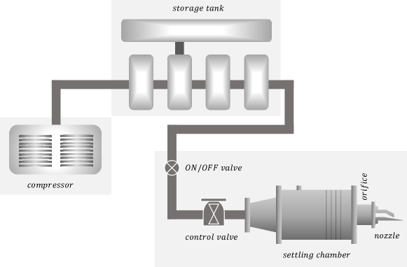
Experiments are conducted in the free jet facility at High-Speed Aerodynamics Laboratory, Indian Institute of Technology Kanpur, India [33]. A schematic of the setup is shown in Figure 1. The facility consists of a multi-stage reciprocating compressor to charge the decontaminated compressed air in the multiple storage tanks. The maximum storage pressure in these tanks is 3.5 MPa. Later, the compressed air from the storage tanks is supplied to the settling chamber through the control valves. Various mesh-screens and honeycombs are positioned inside the settling chamber for flow straightening and conditioning. The designed plug nozzle is connected to the orifice at the end of the stagnation chamber, as shown in Figure 1.
| (m/s) | (m2/s) | (mm) | |||
|---|---|---|---|---|---|
| 3 | 402.95 | 0.89 | 6.01 | 1.36 | 2.69 |
| 6 | 491.41 | 0.62 | 8.09 | 1.83 | 6.42 |
II.2 Experimental Model
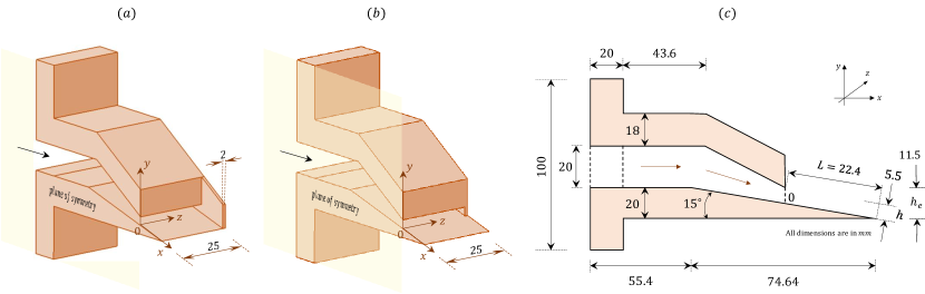
A schematic of the plug nozzle with and without side-walls are shown in Figure 2. The model has a throat height mm, slant length mm, width mm and plug half-angle of . Two different lengths of side plates are used for studying the effect of the side-wall, with one side plate running up to the throat and another side plate till the full-length plug. In total, seven wall-static pressure sensors were placed along the streamwise direction with an axial offset of 3 mm between and . A linear array of the sensors, as mentioned above, is available along the center-line and also close to the side-wall of the planar plug nozzle to compare the effect of the side-wall on the flow field. Typical flow conditions realized during the nozzle run are summarized in Table 1.
II.3 Flow Visualization (Schlieren and oil flow)
In the present work, flow visualization is carried out through a ‘Z-type’ schlieren system [34] for the case without the side-wall as the other case offer challenges in terms of optical access. Schlieren system employs a 3W white LED light source with a power supply (Model: HO-HBL-3W, Holmarc), and a high-speed camera (Model: CH14-1.0-32C, Chronos) for capturing the images along with the appropriate optics. Schlieren mirrors are 200 mm in diameter with a focal length of 1.5 m. The images are captured at a sampling frequency of Hz with a light/frame exposure time of . The frame resolution is 600300 pixels at a spatial resolution of 0.1618 mm/pixel. Spatial fields are scaled using the slant length of the plug surface . Surface flow visualization is also performed with the help of an oil flow visualization technique to compare the flow features of the plug nozzle with and without a side-wall. A mixture of titanium dioxide, oleic acid, and vacuum oil is used for oil flow visualization. A black acrylic sheet of 0.1 mm thickness is pasted on the nozzle plug surface, and the mixture is sprayed on the plug surface to get an insight on the flow feature during the test time. A Nikon® D70 DSLR camera with 16 mega-pixel resolution is used to capture the flow field with a spatial resolution of 0.082 mm/pixel.
II.4 Data acquisition system and pressure measurements (steady and unsteady)
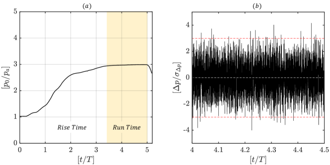
Steady pressure measurements are acquired on the center and side-line of the plug surface using a 16-channel steady pressure scanner (Pressure Systems, Inc., Model-9016). One channel of the pressure scanner is used to measure the stagnation chamber pressure, and others are used to measure the wall-static pressure on the plug surface. A data acquisition system is used to acquire the data at a sampling rate of 50 Hz over a period of 1 s. Unsteady pressure measurements on the plug surface are carried out using PCB® piezotronics pressure sensors (Model-113B24) mounted on the center-line and side-line of the plug surface at selected locations of interest. The data are acquired at a sampling rate of 100 kHz for a duration of 1 s. A typical steady and unsteady pressure signal achieved during the experiments is shown in Figure 3, where the experimental run-time is marked.
II.5 Uncertainty
The sources of uncertainty in the measured and the derived quantities are calculated as per the procedures mentioned in the book of Coleman and Steele [35]. Uncertainty in the measured quantities for the steady and unsteady pressure sensors is calculated to be 3% and 10% about the measured values. Spatial uncertainty in imaging the flow features equals the pixel resolution itself. Thereby, schlieren and oil flow visualization comprises features having a spatial variation of 0.2 mm and 0.1 mm, respectively. The spectral resolution from the unsteady measurements is about 49 Hz.
III Numerical Methodology
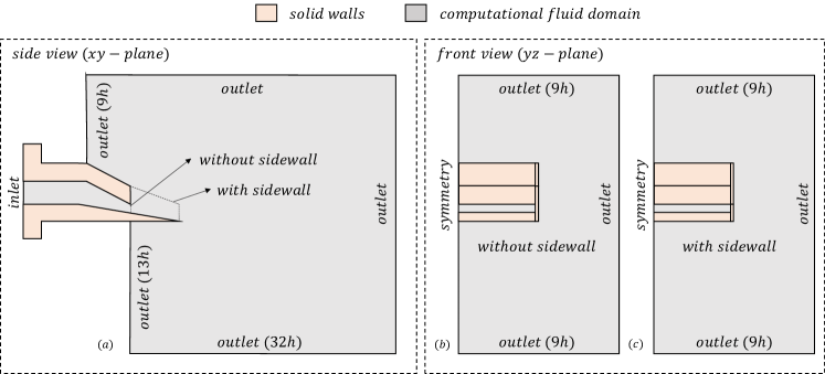
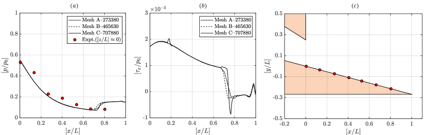
Numerical simulations are carried out using a commercial computational fluid dynamics (CFD) solver Ansys-Fluent® to solve the Reynolds Averaged Navier-Stokes (RANS) equations [36, 37]. The present work involves both two-dimensional and three-dimensional RANS simulations. The CFD domain boundary conditions (wall, symmetry, pressure inlet, and pressure outlet) used in the simulations are also shown in Figure 4. The spatial grids are generated using the Ansys-ICEM® module. The computational cells are of structured quadrilateral types, while an equisize skewness values are contained well below 0.2 for 95% of the cells. A turbulence model of ‘-SST’ (shear stress transport) is used with compressibility corrections and standard wall function as it is known to predict the flow separations in the jet flow field [38, 37]. Near the wall, values are maintained less than 5 [39] with a cell spacing progression being maintained not larger than 1.2 normal to the wall. Grid independence studies are carried out and the results are shown in Figure 5. A final grid (Mesh-C) of million for 2D-RANS and million for 3D-RANS are found to be sufficient for the present analysis. In the coupled pressure-based solver, we use air as the ideal gas. While performing spatial discretization, Green-Gauss node-based method is used to resolve the gradients, and a second-order scheme is used to resolve pressure, density, momentum, turbulent kinetic energy, specific dissipation rate, and energy. A pseudo-transient solution steering methodology, along with hybrid initialization, is adopted for rapid convergence of the solution, and convergence of is achieved in the continuity equation in all the performed computations.
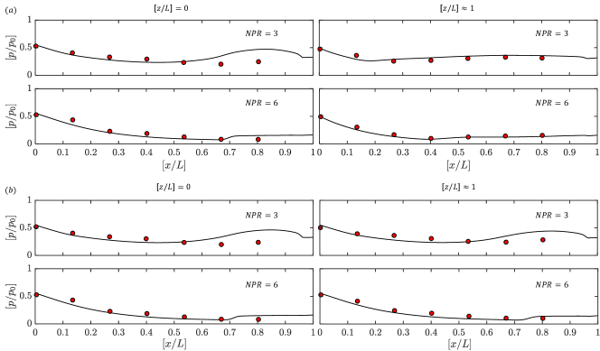
Computations are validated against the present experiments through the wall-static pressure measurements on the planar plug surface, as shown in Figure 6. Measurements along the center-line and close to the side-wall are plotted for both the operating conditions with and without lateral confinement. The numerical results are found to be in good agreement with measurements. The deviation seen closer to the end of the planar-plug surface is attributed to the poor spatial resolution in sensor placement and the inherent size of the sensor itself.
IV Result and Discussions
The effect of the side-wall on the flow dynamics occurring on the planar plug nozzle surface is studied at two different NPR’s (3 and 6), and the jet parameters are tabulated in Table 1. The two conditions are selected as the flow remains attached to the plug surface at NPR=3 and detaches at NPR=6. Qualitative and quantitative comparisons from the flow visualization through schlieren and oil flow technique together with pressure measurements (both steady and unsteady) on the plug surface shed valuable information. Tandem findings from computational results give a clear understanding of the flow field, and the overall results are explained in the following sections.
IV.1 Schlieren imaging at different NPR’s without side-walls
Figure 7 shows the wave structure prevailing in the plug nozzle jet obtained using the schlieren technique. Images on the left side show instantaneous flow field obtained from experiments, whereas, images on the right side show time-averaged flow field generated numerically by calculating the gradients of the density field along the streamwise direction. The comparison is made only for the case without the side-walls presence since it is not possible to obtain experimental schlieren images with the presence of side-wall. A striking similarity between the experimental and the numerical results, especially near the plug surface, is achieved. The pressure distribution on the planar plug nozzle depends on the evolution of the fluid on the plug surface, which is primarily governed by the NPR. The fluid coming from the settling chamber expands internally to sonic state as it reaches the cowl exit. Since the cowl is designed to have a minimum cross-sectional area at the exit, the fluid is choked right at the cowl lip. As the fluid leaves the cowl, it undergoes supersonic expansion on the plug surface. This expansion occurs externally since the jet plume on the ramp surface is exposed. The upper jet boundary is free to adjust to the outer atmosphere. Therefore, external expansion nozzles are capable of adapting to the changing ambient conditions resulting in better off-design performance as compared to conventional nozzles.
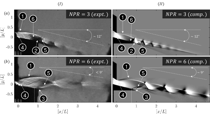
In Figure 7a, flow field for NPR=3 is shown where fluid expands near the cowl through an expansion fan that is centered on the cow lip. In Table 1, the fully expanded jet height () and the apparent jet exit height () are given, where for both the NPR’s. From the free/confined jet nomenclature [14, 40], the farther the values of from , the higher the degree of over-expansion, and it is vice versa if approaches . All the NPR cases are identified to be over-expanded, with the degree of over-expansion being higher for NPR=3 than NPR=6. The nozzle at NPR=3 is highly over-expanded because of which the expansion waves (the white region near the cowl-lip) are confined to a small region of the ramp surface near the cowl exit. These expansion waves are reflected from the ramp towards the outer shear layer. These expansion waves then are reflected from the shear layer as weak compression waves and result in the formation of an over-expansion shock wave on the ramp, as shown in Figure 7a.
The formation of over-expansion shock wave causes a sudden rise in the static pressure distribution on the ramp surface, as evident from Figure 6. The shock wave interacts with the upper shear (white) layer and is reflected as expansion waves towards the lower shear layer (black). The back and forth a reflection of shocks and expansion waves results in the formation of a shock-cell structure that is confined within the supersonic core of the jet. The supersonic core is bounded by the upper and the lower shear layer, as can be seen from the schlieren image (Figure 7a). The jet remains attached to the ramp surface, and no evidence of flow separation is observed. The boundary of the jet is straight, and the jet itself is aligned with the plug surface with the same inclination of , as shown in Figure 2c. After leaving the plug surface, the jet trajectory is inclined to with the horizontal plane.
As the NPR is increased to 6, as shown in Figure 7b, the jet expands strongly near the cowl lip. The free shear layer opens up to a width more extensive than that of the NPR=3 cases. As the jet width rapidly increases in the free shear layer side, the fully-expanded jet width is realized well before the termination of the plug wall surface. Hence, the flow separates shortly before leaving the plug surface. Because of the separation, the jet boundary turns away from the plug surface through a strong oblique shock, as shown in Figure 7b. The difference in jet inclination angle between the experiments and CFD at NPR=6 in Figure 7b is due to the imaging limitations of the camera, three-dimensional line of sight light integration and the fact that the jet is flapping (unsteady). However, the gross flow features like the separation point on the plug-surface, jet inclination being smaller than the NPR=3 case are still observed in the image.
Since the nozzle plug surface is linear and is not designed for smooth expansion, a strong oblique shock wave is inevitable, and it stands near the tip of the plug surface. Due to the strong oblique shock wave encounter, the boundary layer separates from the ramp wall, and the lower shear layer is turned away from the wall. The interaction of the oblique shock wave with the boundary layer is often responsible for the generation of unsteady pressure fluctuations on the wall, which is discussed in the upcoming section. A more extended supersonic core with bigger shock cells in comparison to NPR=3 is observed for NPR=6. After separation at , the jet trajectory is inclined at even a lesser angle with the horizontal plane than that of the previous.
IV.2 Oil flow visualization
The images obtained from the oil flow visualization technique are processed using MATLAB® and are compared with the computational results. The values of shear stress () along the -direction is calculated using the Equation 1 (where -dynamic viscosity, -velocity components in directions) mentioned below to compare the numerical results with the experiments. Parallel comparison of streaks from the oil flow visualization with the total streamwise shear stress from the computations is given in Figure 8.
| (1) |
As it is evident from Figure 8, flow for NPR=3 is attached, whereas, for NPR=6, it is separated. Lateral confinement keeps the flow features relatively two dimensional (separation line being straight), whereas free lateral expansion forms symmetrical jet distortions about the symmetry plane (separation line being curved). Separation lines are marked using the dotted yellow line in Figure 8-Ia and 8-Ib. The separation line is found to be closer to the throat when there is a free lateral expansion , whereas lateral confinement keeps the separation slightly away from the throat .
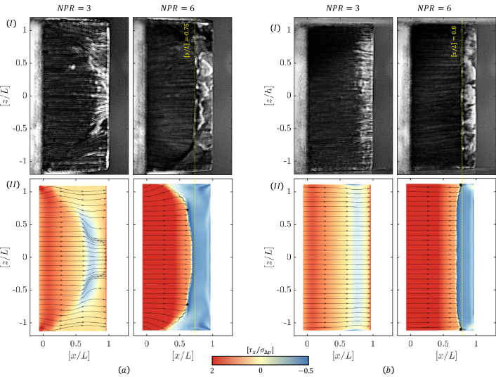
Corresponding computations also reveal almost the same features. Streamlines drawn closer to the wall marks the distorted and separation zones. The separation zones could be readily identified in Figure 8-IIa and 8-IIb for NPR=6 by seeing the absence of streamlines around the trailing edge of the planar plug nozzle . An oblique shock forms at the point of separation as the nozzle flow is supersonic upstream. In the case with no lateral confinement, three-dimensional separation leads to the formation of curved shocks.
For the considered NPR’s, the expansion fan from the nozzle lip and the surface comes in contact with the lateral free shear layer. Upon impinging the free boundary, the expansion fan is reflected as compression waves. The fluid from the jet periphery thus takes a curvilinear profile towards the center-line, leading to the observation of curved shocks. Such a behaviour is well seen through the streamlines drawn from the computational studies in Figure 8-IIa. A similar phenomenon is also documented in the compressible free jet studies on the planar rectangular nozzle jet[41], rectangular nozzle jet with after deck[42, 43, 44], supersonic wall-jet flows[45] and linear cluster plug nozzle jet[46].
The observation from pressure plots shown in Figure 6 strongly suggests that there is a sudden rise in the wall pressure values at locations predicted by qualitative visualization from oil flow experiments and numerical results (shown in Figure 8). The rise in pressure values is mainly due to the presence of over-expansion shockwaves on the pug surface. These shockwaves interact with the growing boundary layer. The interaction results in the thickening of the boundary layer and eventually leads to flow separation and results in the formation of a recirculation bubble on its surface. The portion on the plug surface where the shock interacts with the boundary layer is hereafter called the interaction region.
The oil flow visualizations reveal that the flow remains attached for NPR=3, irrespective of the lateral confinement. On the contrary, for NPR=6, a recirculation bubble can be seen due to separation. The absence of lateral confinement makes the separation further three-dimensional. The shock wave on the plug surface for NPR=3 might not be strong enough to cause the flow separation; instead, the boundary layer thickens due to the presence of an adverse pressure gradient.
The flow Mach number variation along the center-line and side-line of the plug surface was evaluated using isentropic relation until the shock location on the plug surface. An increment in the magnitude of Mach number from 1.38 to 1.83 is observed at the center-line with side-wall as NPR increases from 3 to 6. Due to this increase in Mach number, the shock strength is enhanced, and the interaction with the boundary layer is stronger, thereby resulting in a larger interaction region and a larger recirculation bubble for NPR=6. Additionally, flow acceleration near the side-wall due to the displacement effect of the side-wall boundary layer aids in making the flow more resistant to separation [47, 48].
IV.3 Pressure distribution
IV.3.1 Center-line pressure measurements
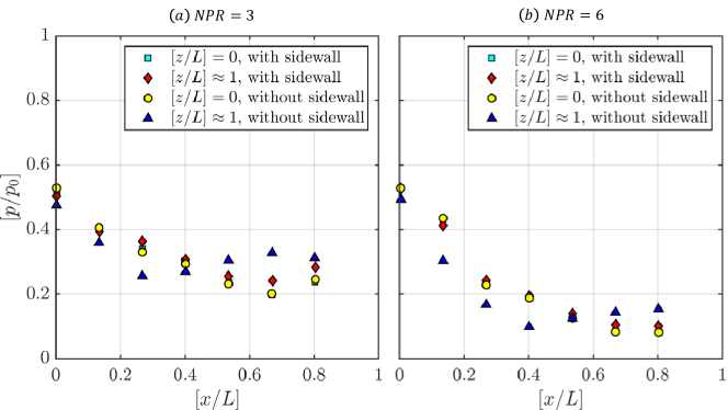
Figure 9 depicts the wall-static pressure measurement over the plug surface in which represents the position of the throat, and the x-axis is non-dimensionalized by the slant-height of the plug surface . Along the center-line of the plug surface, , the normalized wall-static pressure distribution is invariant among the cases with and without side-wall for both the NPR’s under investigation.
Values of decrease along the flow direction due to the expansion of the flow until the location , after which a rise in pressure was observed at , which is the last available port for pressure measurements. Somewhere between and 0.8, there exist a region where a sudden pressure jump should be occurring. Based on the schlieren and oil flow visualization, we observe that this pressure rise is achieved through over-expansion oblique shockwave. This mechanism exists to equalize the expanding gas pressure to the ambient pressure .
Unlike the NPR=3 case, for NPR=6, no significant rise in pressure values were observed along the plug surface; however, schlieren visualization (both experimental and numerical) showed a strong oblique shock wave. As a result of the higher strength of this over-expansion shock, more rise in static pressure was expected; nevertheless, the presence of interaction region (Figure 8) and the characteristic altitude adaptability of the pug nozzle played a vital role in decreasing the degree of increment in pressure, thereby less rise in pressure was perceived as can be seen from Figure 6.
IV.3.2 Sideline pressure measurements
Along the side-line at in the presence of the side-wall, the pressure distribution is different (Figure 9). It is slightly higher when compared to the measurements at , owing to the developing boundary layer on the plug surface and the side-wall. However, the pressure distribution trend and the location of the oblique shock wave on the plug surface are similar to those along the center-line . Such observations also confirm that the separation line formed due to the oblique shock wave along the spanwise direction is straight, suggesting the flow field along the plug surface remains almost two dimensional in the absence of the side-walls at NPR=6. In the absence of a side-wall, there is a rapid expansion of jet in the lateral direction starting from the throat region. This is, in turn, confirmed by the pressure measurements (see Figure 9) along the side-line at , which showed a huge difference in pressure values compared to the case with the side-wall being present. The separation line thus cannot be two-dimensional for the case without the side-wall. The interaction is complex and three-dimensional. Moreover, in the absence of side-wall, along the sideline of the plug surface, the pressure jump is around for NPR=3 and around for NPR=6, in contrary to the pressure rise along the center-line . This intuitively suggests that the separation line due to the oblique shock wave is curved due to lateral expansion.
IV.4 Power spectra
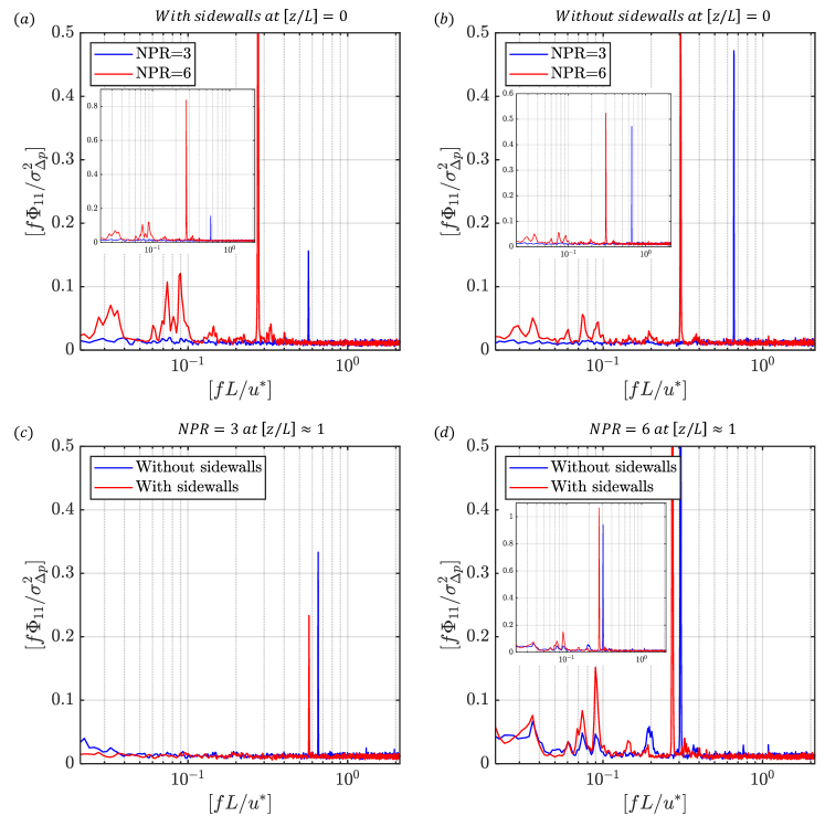
The flow field on the plug surface is observed to be unsteady from both schlieren and oil flow visualization. In order to study the temporal characteristics of the dynamic pressure signal in the interaction region, a spectral analysis is carried out using the pwelch method (Hamming window with 50% overlap between segments) using MATLAB® to deduce the frequency spectrum and the associated Power Spectral Density (PSD). Since the objective of the present investigation is to study the effect of lateral confinement on plug surface flow field, the spectral analysis is carried out only for two locations inside the interaction region: along the center-line and closer to the side-wall at . The pre-multiplied PSD is normalized using a common variance for the comparison of different cases. The obtained spectra for NPR=3 and 6, at the center-line with the lateral confinement, is plotted in Figure 10a.
The spectra show a notable difference, especially in the low-frequency range. The spectra do not show any significant spectral feature except for a dominant peak around 8 kHz for NPR=3, where the flow remains attached to the plug surface. On the other hand, NPR=6, where the flow is separated due to shockwave-boundary layer interaction, has shown several spectral features, Hz (). Two significant broadband spectra were observed, the first one between 0.35 – 0.48 kHz (0.025 - 0.034) with a peak value at 0.45 kHz and the second one between 1 – 1.6 kHz (0.07 - 0.113) with dominant peaks at 1.1 kHz (0.078) and 1.5 kHz (0.106). While the low-frequency large-amplitude fluctuations (0.45 kHz, ) can be attributed to the oscillation of separation shock foot [26], the high-frequency high-amplitude fluctuation (1 – 1.6 kHz) can be due to the motions induced by shock-shear layer interactions [21, 49]. However, the amplitude of the aforementioned spectra is minimal here in comparison with the dominant tone observed around 4 kHz (0.3). The reason is primarily because of the different nozzle configuration (conventional C-D nozzle [21]). The influence of screeching or the production of distinct high-frequency sound pulse/spherical wave-front, occurring outside the nozzle due to jet-flapping, is attenuated considerably due to the bounding walls of the nozzle walls unlike the plug nozzle. However, in a plug nozzle, most of the jet boundary is exposed to the atmosphere which can be subjected to the perturbation of screeching.
Other spectral features observed for NPR=6 are bands centered around 2 kHz (0.141) and 4.5 kHz (0.318); however, their amplitudes are very less when compared to others. In the absence of lateral confinement, the spectral features remained the same for both the NPR’s except that their amplitude is smaller, as shown in Figure 10b. Irrespective of the lateral confinement, a prominent peak of equivalent power is observed at 0.85 kHz (0.0601) for NPR=6. For NPR=3 the strength of the shock is weaker when compared with NPR=6, hence, its intensity or energy level is very minimal when compared with its other dominant spectral feature and those of NPR=6. Earlier works on the plug nozzle also reported a similar peak at the same frequency and have associated it with the over-expansion shock [31, 32]. However, the researchers utilized a linear cluster of plug nozzles which is moderately different in comparison to the one used in our present experiments. Linear clusters offer shielding in a similar way to that of a side-wall where the associated flow physics partially differ from the present one. In addition, the researchers used an extended cowl where part of the jet-expansion had already happened internally. In the present case, flow expansion begins from the throat itself (freely on one side and bounded by the plug nozzle surface on the other side). Besides, the high frequency oscillations[31, 32] are only prominent at NPR 8.8 (Fig 5b) and not at the present operating conditions under discussion. Apart from the different NPR conditions, there was a strong base flow which provides further shielding and additional flow features, especially the reduced percentage of exposed separation zone prone to screech effects at lower NPR.
Similar to NPR=3 having a dominant peak around 8 kHz (), NPR=6 also exhibits a dominant peak, however, it is observed at 3.85 kHz (). Similar observations were also reported in the earlier research works on plug nozzles [31, 32], where they observed dominant frequency at 3.36 kHz (0.2375) for NPR11 and at 3.8 kHz (0.2686) at NPR9. These high frequencies are attributed to the overall unsteadiness on the plug surface, and it is reported that the entire flow was fluctuating at this single frequency. However, from our present studies, we speculate that these frequencies are due to acoustic screech. The acoustic radiation generated downstream of the nozzle exit propagates upstream and interacts with the thin shear layer at the nozzle lip. While doing so, the upstream travelling disturbances intensify the instabilities in the shear layer. The amplified instabilities from the shear layer are further convected downstream and contribute to the production of acoustic radiation. The generated acoustic radiation then again propagates upstream, thereby forming a feedback loop and establishes the basis for discrete frequency generation by the jet flow [50]. Unlike conventional C-D nozzle, this interaction of acoustic radiation with the shear layer occurs at the throat exit, due to the absence of plug on the upper throat-lip, thereby influencing the fluctuations on the plug surface in the bottom throat-lip. This feature of acoustic screech influencing the fluctuation on the plug surface seems to be a characteristic of plug nozzle.
The dominant frequency in Figure 10b is found to decrease from 9.3 kHz (0.6573) to 4.35 kHz (0.3074) with an increase in NPR from 3 to 6. The behavior of lower-shifting of the peak frequency with an increase in NPR is similar to that of the events observed in the free jets [49]. Notably, the screeching frequency is attributed to the Mode-B events observed at higher frequency kHz) (between 4 to 8 kHz) when the NPR is between 3-7.
The spectra from the unsteady pressure signal measured along the side-line , in the presence and absence of side-wall, for different NPR’s are shown in Figure 10c-d. For both the NPR’s, no noticeable changes in the spectral lines are observed due to the lateral confinement in comparison with the spectra seen at the center-line , except a slight power drop. However, the power of the dominant frequency for NPR=6 is increased significantly in the absence of the side-wall. For NPR=6, the spectral features are similar to those observed at the center-line; however, in the absence of side-wall, their amplitudes in the frequency range of 1 – 1.5 kHz (0.071 - 0.106) are noticeably lower owing to the sideways spillage of the separated flow. On the other hand, the spectra had the same amplitude at 0.4 kHz (0.0283) and 0.85 kHz (0.0601) both in the presence and absence of the side-wall.
Another noticeable event includes the influence of the screech on the interaction region. Even though the flow is attached in NPR=3, when the lateral confinement is absent, the flow is forced by the screech frequency. The influence is seen in Figure 10c, where the power is almost twice the case with lateral walls. In addition, a small positive shift in frequency is seen for both the operating conditions. The downstream acoustic forcing of the upstream screech through the subsonic portion of the boundary layer might create such narrow spectra at the point of measurement.
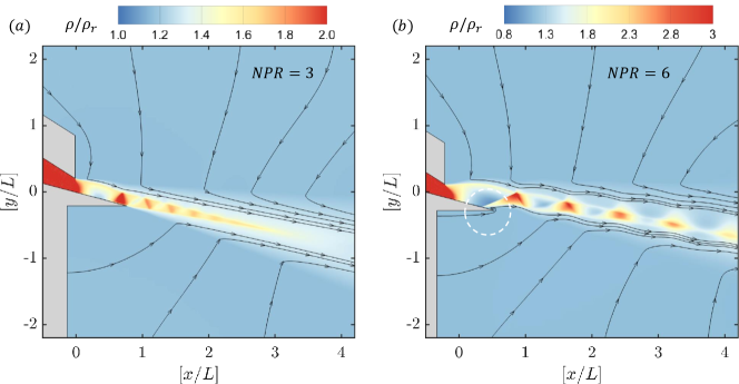
From the computational results in Figure 11, the communication or forcing from the environment back to the interaction region is seen between the two different NPR conditions. At NPR=3, the flow is observed to be attached, and the separated shear layer is comparatively thinner than the NPR=6 case. At NPR=6, due to flow separation on the ramp wall surface, the streamlines from the ambient pass through the separation zone (the region is marked as a dotted white circle). In the absence of lateral confinement for different NPR’s, tonal disturbances from the screech (Mode-B) severely influence the unsteady dynamics around the flow separation zone, which explain the varying power levels observed on the dominant frequency between NPR=6 and NPR=3 at in Figure 10c-d.
IV.5 Three-dimensional effects
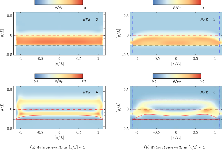
As evident from the previous measurements, three-dimensional events are prominent in the absence of lateral confinement. Computational results from the transverse planes are analyzed to assess the extent of the three-dimensional flow features. Slices are taken at in all the cases, and the normalized density contours are visualized. From Figure 12, the flow seems two-dimensional only for NPR=3 under lateral confinement. For higher NPR, three-dimensional features start to propagate from the walls to the core. The separation is predominant in the core flow, and the jet remains attached closer to the wall. On the contrary, the jet structure is three dimensional for both the NPR’s when there is a free lateral expansion. However, the severity is more for NPR=6 cases. A visible distorted mouth-like structure could be seen with a strong lifted-up vortex closer to the extrema of the nozzle. The effective jet diameter leaving the plug nozzle under such strong three dimensional interactions would be much less as seen in Figure 12b. These changes alter the near and far-field jet characteristics, in addition to the variations observed on the side load characteristics.
V Conclusions
A planar plug nozzle with and without side-walls are analyzed both numerically and experimentally at two different over-expanded nozzle pressure ratio (NPR=3 and 6). Schlieren and oil flow visualization are used as qualitative tools, whereas the steady and unsteady pressure measurements are utilized to extract quantitative information. Computations are identified to replicate results closer to experiments. Experimentally inaccessible flow planes are visualized computationally to extract flow physics. Following are the major conclusions from our study:
-
•
Lateral confinement keeps the separation at higher NPR fairly two-dimensional. Upon free lateral expansion, the separation zones are observed to be larger and three-dimensional.
-
•
At higher NPR’s, unsteady flow separation is severe and observed to be in the low-frequency range.
-
•
The frequency contents prominently shift to higher values due to the presence of confinement irrespective of NPR’s. However, during free lateral expansion when there is no confinement, the power of the spectrum drops drastically.
-
•
Lateral confinement offers shielding from the downstream screech, which reduces the power to almost half of the value.
Author’s Contributions
All authors have contributed equally to this work.
Data Availability
The data that support the findings of this study are available from the corresponding author upon reasonable request.
Acknowledgments
The authors would like to thank Mr. Rohit Panthi, Mr. Shishupal Singh Sachan, and Mr. Suresh Mishra for their help during the experimental work. The financial support from the Department of Aerospace Engineering, Indian Institute of Technology, Kanpur, for carrying out the research work is gratefully acknowledged. The authors also acknowledge the support of Indian Institute of Technology Kanpur (IITK) (www.iitk.ac.in/cc) for providing the resources to carry out the simulation, and data analysis as well. The authors gratefully acknowledge the useful comments of the reviewers in shaping the manuscript.
References
- Aukerman [1991] C. Aukerman, “Plug nozzles - the ultimate customer driven propulsion system,” in 27th Joint Propulsion Conference (American Institute of Aeronautics and Astronautics, 1991).
- Sutton [2006] G. P. Sutton, History of Liquid Propellant Rocket Engines (American Institute of Aeronautics and Astronautics, 2006).
- Griffith [1954] A. A. Griffith, “Jet-propulsion nozzle for use at supersonic jet velocities,” (1954), uS Patent US2683962A.
- Hagemann et al. [1998] G. Hagemann, H. Immich, T. V. Nguyen, and G. E. Dumnov, “Advanced rocket nozzles,” Journal of Propulsion and Power 14, 620–634 (1998).
- Ruf et al. [1997] J. Ruf, P. McConaughey, J. Ruf, and P. McConaughey, “The plume physics behind aerospike nozzle altitude compensation and slipstream effect,” in 33rd Joint Propulsion Conference and Exhibit (American Institute of Aeronautics and Astronautics, 1997).
- Onofri et al. [2002] M. Onofri, M. Calabro, G. Hagemann, H. Immich, P. Sacher, F. Nasuti, and P. Reijasse, “Plug nozzles: summary of flow features and engine performance - overview of RTO/AVT WG 10 subgroup 1,” in 40th AIAA Aerospace Sciences Meeting & Exhibit (American Institute of Aeronautics and Astronautics, 2002).
- Chutkey, Vasudevan, and Balakrishnan [2012] K. Chutkey, B. Vasudevan, and N. Balakrishnan, “Flowfield analysis of linear plug nozzle,” Journal of Spacecraft and Rockets 49, 1109–1119 (2012).
- Tomita, Tamura, and Takahashi [1996] T. Tomita, H. Tamura, and M. Takahashi, “An experimental evaluation of plug nozzle flow field,” in 32nd Joint Propulsion Conference and Exhibit (American Institute of Aeronautics and Astronautics, 1996).
- Romine [1998] G. L. Romine, “Nozzle flow separation,” AIAA Journal 36, 1618–1625 (1998).
- Zebiri et al. [2020] B. Zebiri, A. Piquet, A. Hadjadj, and S. B. Verma, “Shock-induced flow separation in an overexpanded supersonic planar nozzle,” AIAA Journal 58, 2122–2131 (2020).
- Hamed and Vogiatzis [1998] A. Hamed and C. Vogiatzis, “Overexpanded two-dimensional convergent-divergent nozzle performance, effects of three-dimensional flow interactions,” Journal of Propulsion and Power 14, 234–240 (1998).
- O¨stlund and Muhammad-Klingmann [2005] J. O¨stlund and B. Muhammad-Klingmann, “Supersonic flow separation with application to rocket engine nozzles,” Applied Mechanics Reviews 58, 143–177 (2005).
- Gupta, Rao, and Kumar [2019] P. Gupta, S. M. V. Rao, and P. Kumar, “Experimental investigations on mixing characteristics in the critical regime of a low-area ratio supersonic ejector,” Physics of Fluids 31, 026101 (2019).
- Karthick et al. [2016] S. K. Karthick, S. M. V. Rao, G. Jagadeesh, and K. P. J. Reddy, “Parametric experimental studies on mixing characteristics within a low area ratio rectangular supersonic gaseous ejector,” Physics of Fluids 28, 076101 (2016).
- Kumar et al. [2018] P. A. Kumar, S. M. A. Kumar, A. S. Mitra, and E. Rathakrishnan, “Fluidic injectors for supersonic jet control,” Physics of Fluids 30, 126101 (2018).
- Kumar et al. [2019] P. A. Kumar, S. M. A. Kumar, A. S. Mitra, and E. Rathakrishnan, “Empirical scaling analysis of supersonic jet control using steady fluidic injection,” Physics of Fluids 31, 056107 (2019).
- Kumar, Aileni, and Rathakrishnan [2019] P. A. Kumar, M. Aileni, and E. Rathakrishnan, “Impact of tab location relative to the nozzle exit on the shock structure of a supersonic jet,” Physics of Fluids 31, 076104 (2019).
- Frey and Hagemann [1999] M. Frey and G. Hagemann, “Flow separation and side-loads in rocket nozzles,” in 35th Joint Propulsion Conference and Exhibit (American Institute of Aeronautics and Astronautics, 1999).
- Verma [2008] S. B. Verma, “Shock unsteadiness in a thrust optimized parabolic nozzle,” Shock Waves 19, 193–212 (2008).
- Johnson and Papamoschou [2010] A. D. Johnson and D. Papamoschou, “Instability of shock-induced nozzle flow separation,” Physics of Fluids 22, 016102 (2010).
- Olson and Lele [2013] B. J. Olson and S. K. Lele, “A mechanism for unsteady separation in over-expanded nozzle flow,” Physics of Fluids 25, 110809 (2013).
- Lawrence [1967] R. A. Lawrence, “Symmetrical and Unsymmetrical Flow Separation in Supersonic Nozzles,” Tech. Rep. NASA-CR-92587 (Southern Methodist Univ., Dallas, Tex. Inst. of Technology, 1967).
- Reijasse, Corbel, and Soulevant [1999] P. Reijasse, B. Corbel, and D. Soulevant, “Unsteadiness and asymmetry of shock-induced separation in a planar two-dimensional nozzle - a flow description,” in 30th Fluid Dynamics Conference (American Institute of Aeronautics and Astronautics, 1999).
- Bourgoing and Reijasse [2005] A. Bourgoing and P. Reijasse, “Experimental analysis of unsteady separated flows in a supersonic planar nozzle,” Shock Waves 14, 251–258 (2005).
- Papamoschou, Zill, and Johnson [2008] D. Papamoschou, A. Zill, and A. Johnson, “Supersonic flow separation in planar nozzles,” Shock Waves 19, 171–183 (2008).
- Verma and Haidn [2014] S. Verma and O. Haidn, “Unsteady shock motions in an over-expanded parabolic rocket nozzle,” Aerospace Science and Technology 39, 48–71 (2014).
- Verma and Manisankar [2014] S. B. Verma and C. Manisankar, “Origin of flow asymmetry in planar nozzles with separation,” Shock Waves 24, 191–209 (2014).
- Miyamoto, Matsuo, and Kojima [2006] H. Miyamoto, A. Matsuo, and T. Kojima, “Effects of sidewall configurations on rectangular plug nozzle performance,” in 42nd AIAA/ASME/SAE/ASEE Joint Propulsion Conference & Exhibit (American Institute of Aeronautics and Astronautics, 2006).
- Ito, Fujii, and Hagemann [2004] T. Ito, K. Fujii, and G. Hagemann, “Numerical investigations of the side fence effect on linear plug nozzle performance,” in 40th AIAA/ASME/SAE/ASEE Joint Propulsion Conference and Exhibit (American Institute of Aeronautics and Astronautics, 2004).
- Mori et al. [2005] H. Mori, T. Niimi, M. Taniguchi, R. Nishihira, and A. Fukushima, “Experimental analyses of linear-type aerospike nozzles with sidewalls,” in ICIASF 2005 RecordInternational Congress on Instrumentation in Aerospace Simulation Facilities (IEEE, 2005).
- Verma and Viji [2011] S. Verma and M. Viji, “Linear-plug flowfield and base pressure development in freestream flow,” Journal of Propulsion and Power 27, 1247–1258 (2011).
- Chutkey, Viji, and Verma [2017] K. Chutkey, M. Viji, and S. B. Verma, “Effect of clustering on linear plug nozzle flow field for overexpanded internal jet,” Shock Waves 27, 623–633 (2017).
- Khan et al. [2019] A. Khan, R. Panthi, R. Kumar, and S. M. Ibrahim, “Experimental investigation of the effect of extended cowl on the flow field of planar plug nozzles,” Aerospace Science and Technology 88, 208–221 (2019).
- Settles [2001] G. S. Settles, Schlieren and Shadowgraph Techniques (Springer Berlin Heidelberg, 2001).
- Coleman and Steele [2009] H. W. Coleman and W. G. Steele, “Experimentation, errors, and uncertainty,” in Experimentation, Validation, and Uncertainty Analysis for Engineers (John Wiley & Sons, Inc., 2009) pp. 1–27.
- Alam et al. [2016] M. Alam, T. Setoguchi, S. Matsuo, and H. Kim, “Nozzle geometry variations on the discharge coefficient,” Propulsion and Power Research 5, 22–33 (2016).
- Shimshi, Ben-Dor, and Levy [2009] E. Shimshi, G. Ben-Dor, and A. Levy, “Viscous simulation of shock-reflection hysteresis in overexpanded planar nozzles,” Journal of Fluid Mechanics 635, 189–206 (2009).
- Balabel et al. [2011] A. Balabel, A. Hegab, M. Nasr, and S. M. El-Behery, “Assessment of turbulence modeling for gas flow in two-dimensional convergent–divergent rocket nozzle,” Applied Mathematical Modelling 35, 3408–3422 (2011).
- Yu et al. [2012] Y. Yu, M. Shademan, R. M. Barron, and R. Balachandar, “CFD study of effects of geometry variations on flow in a nozzle,” Engineering Applications of Computational Fluid Mechanics 6, 412–425 (2012).
- Tam and Tanna [1982] C. Tam and H. Tanna, “Shock associated noise of supersonic jets from convergent-divergent nozzles,” Journal of Sound and Vibration 81, 337–358 (1982).
- Behrouzi, McGuirk, and Avenell [2018] P. Behrouzi, J. J. McGuirk, and C. Avenell, “Effect of scarfing on rectangular nozzle supersonic jet plume flow characteristics,” AIAA Journal 56, 301–315 (2018).
- Frate and Bridges [2011] F. Frate and J. Bridges, “Extensible rectangular nozzle model system,” in 49th AIAA Aerospace Sciences Meeting including the New Horizons Forum and Aerospace Exposition (American Institute of Aeronautics and Astronautics, 2011).
- Behrouzi and McGuirk [2015] P. Behrouzi and J. J. McGuirk, “Underexpanded jet development from a rectangular nozzle with aft-deck,” AIAA Journal 53, 1287–1298 (2015).
- Stack and Gaitonde [2018] C. M. Stack and D. V. Gaitonde, “Shear layer dynamics in a supersonic rectangular multistream nozzle with an aft-deck,” AIAA Journal 56, 4348–4360 (2018).
- Kwak and Lee [2016] J.-Y. Kwak and Y. Lee, “An experimental study on the characteristics of rectangular supersonic jet on a flat plate,” International Journal of Aeronautical and Space Sciences 17, 324–331 (2016).
- Chutkey, Viji, and Verma [2018] K. Chutkey, M. Viji, and S. B. Verma, “Interaction of external flow with linear cluster plug nozzle jet,” Shock Waves 28, 1207–1221 (2018).
- Sudani et al. [1993] N. Sudani, M. Sato, H. Kanda, and K. Matsuno, “Flow visualization studies on sidewall effects in two dimensional transonic airfoil testing,” in 31st Aerospace Sciences Meeting (American Institute of Aeronautics and Astronautics, 1993).
- Su [1989] Y. Su, “Mechanism of sidewall effect studied with oil flow visualization,” AIAA Journal 27, 1828–1830 (1989).
- Chen et al. [2018] Z. Chen, J.-H. Wu, A.-D. Ren, and X. Chen, “Mode-switching and nonlinear effects in supersonic jet noise,” AIP Advances 8, 015126 (2018).
- Tam [1995] C. K. W. Tam, “Supersonic jet noise,” Annual Review of Fluid Mechanics 27, 17–43 (1995).