Geometric concepts for stellarator permanent magnet arrays
Abstract
The development of stellarators that use permanent magnet arrays to shape their confining magnetic fields has been a topic of recent interest, but the requirements for how such magnets must be shaped, manufactured, and assembled remain to be determined. To address these open questions, we have performed a study of geometric concepts for magnet arrays with the aid of the newly developed Magpie code. A proposed experiment similar to the National Compact Stellarator Experiment (NCSX) is used as a test case. Two classes of magnet geometry are explored: curved bricks that conform to a regular grid in cylindrical coordinates, and hexahedra that conform to the toroidal plasma geometry. In addition, we test constraints on the magnet polarization. While magnet configurations constrained to be polarized normally to a toroidal surface around the plasma are unable to meet the required magnetic field parameters when subject to physical limitations on the strength of present-day magnets, configurations with unconstrained polarizations are shown to satisfy the physics requirements for a targeted plasma.
1 Introduction
The stellarator, a nonaxisymmetric toroidal plasma confinement device, is a potentially attractive concept for a fusion reactor. It offers some inherent advantages over the axisymmetric tokamak, including the ability to run at steady state with little to no plasma current and a lower risk of disruptions. To realize these advantages, the three-dimensional confining magnetic field must be carefully designed to avoid excessive neoclassical losses [1].
For all optimized stellarators constructed to date, the optimized magnetic field properties have been obtained through the design of non-planar coils [2, 3, 4]. One widely-used approach for designing such coils involves defining a toroidal winding surface and computing the surface current distribution required to accommodate a desired plasma contained within the surface [5]. The surface current distribution can then be discretized to determine the geometry of modular stellarator coils. This is the underlying approach of the Nescoil and Regcoil codes [6]. Recently it was shown that an equivalent mathematical approach can be employed to calculate a distribution of magnetization within a toroidal region enclosing the plasma [7]. This magnetized region, in combination with a simple (e.g., planar) coil set to provide a toroidal magnetic field component, can in principle confine a stellarator plasma just as well as the surface current distribution.
While permanent magnet arrays have not been employed in stellarators to date, they have been designed and built to provide high-precision magnetic fields with strengths of up to 1 T or greater in many other applications, including particle accelerators [8, 9, 10], electric motors [11], free-electron lasers [12, 13], and magnetic resonance imaging [14]. The rare-Earth magnets typically used in such arrays can withstand background fields of up to 2.8 T at room temperature and up to 6 T at the temperature of liquid nitrogen without demagnetizing [15]. Recent advances in the synthesis of magnetic material based on iron-nitrogen compounds have attained remanent fields of greater than 2 T [16, 17], nearly twice the level of rare-Earth magnets.
The incorporation of permanent magnets to supplement the magnetic field produced by coils has the potential to simplify the construction and maintenance of stellarator reactors. The contributions of permanent magnets to the three-dimensional field shaping may enable the use of simpler coils or even eliminate the need for non-planar coils, one of the main drivers of the cost and complexity of stellarator construction [18, 19, 20]. Similarly to coils, permanent magnets would require cooling and neutron radiation shielding to prevent degradation [21]. However, the magnets may consist of bulk material and be partitioned into arbitrarily small modules, suggesting lower costs, less-stringent constraints for fabrication and assembly, and easier device access in comparison to coils.
While permanent magnets offer potential benefits in principle, their use in stellarators has not been extensively studied or tested. One central challenge in realizing a permanent magnet-based stellarator will be to develop a magnet arrangement that meets the physical requirements for effective plasma confinement while also being feasible to construct. In a close analogue to traditional coil-based stellarator designs, which must consist of discrete coils with limitations on current density and curvature, permanent magnet-based stellarator designs must be compatible with limitations on magnetization levels in present-day materials. In addition, while arrays of magnets with arbitrary distributions of strength and polarization direction offer many degrees of freedom toward attaining an optimal confining field, they must ultimately be feasible to mount and enable periodic disassembly and reassembly for reactor maintenance.
A number of recent developments have been made toward attaining optimal permanent-magnet distributions with realistic properties. Regcoil-PM111https://doi.org/10.5281/zenodo.3934702 uses an analogous approach to that of Regcoil to compute continuous distributions of magnetization within toroidal volumes [22]. Zhu et al. [23] introduced a linear method to design arrays of magnets with polarizations constrained to be perpendicular to a toroidal winding surface. The Famus code [24], based on the Focus code for stellarator coil design [25], optimizes an arbitrary distribution of magnetic dipoles representing a discrete array of magnets.
Famus offers complete flexibility on the quantity and spatial distribution of the magnets whose dipole moment is to be optimized. The user must therefore supply a geometric arrangement that adequately represents an array of magnets that is feasible to construct and obeys physical limitations on magnetization. As one approach toward meeting this need, we have developed the Magpie (Magnets, piecewise) code. Magpie generates arrays of magnets with simple shapes subject to intuitive geometric constraints. The output can be used both as input to Famus to optimize the distribution of magnet strength, as well as a starting point for engineering design of the magnets once the required strengths are determined. The ability of the code to rapidly ( 30 s on a standard PC) generate feasible magnet arrangements will enable iterations with physics codes to attain plasmas that possess both desirable physics properties and magnetic field requirements that can be met with permanent magnets.
In this paper, we introduce the code and apply it to design and assess magnet arrangements for a small-scale stellarator based on the National Compact Stellarator Experiment (NCSX) [26, 27]. Sec. 2 describes the two geometric concepts for magnet arrays that are investigated in the paper: curved bricks, which conform to a grid in cylindrical coordinates, and quadrilaterally-faced hexahedra, which conform to the geometry of a smooth toroidal surface around the plasma. Sec. 3 describes a study of hexahedral configurations with the simplifying constraint that all magnets must be locally perpendicular to the toroidal limiting surface. The results indicate that such a constraint cannot be achieved with the limitations on magnet strength in present-day materials. Sec. 4 describes studies of hexahedron and brick configurations in which the polarization direction of each magnet is a free optimization parameter. With this additional degree of freedom, it is possible to attain magnet configurations that meet the physics requirements for the target plasma equilibrium. We discuss the differences between solutions employing hexahedral and brick magnets. In Sec. 5, we demonstrate that both geometries admit viable solutions even after removing magnets that would collide with access ports foreseen for NCSX. In addition, the effects of requirements on spacing between magnets for mounting structures are quantified.
2 Geometric concepts
As with stellarator coil design, the problem of specifying a magnet array to confine a three-dimensional plasma is fundamentally ill-posed [6], and any given plasma configuration will admit many possible solutions. In this study, we explore two classes of solutions that represent different approaches to the magnet array design. In one approach, the magnets all conform to a regular grid; in the other, the magnets are are given custom shaping to conform closely to the toroidal plasma geometry.
2.1 Curved bricks
The grid-conforming magnets in considered here have the geometry of curved bricks. The shape of each brick may be fully specified by six parameters, consisting of lower and upper limits on the radial coordinate , vertical coordinate , and azimuthal (toroidal) angle . The arrays of curved bricks studied to date have been further constrained such that each brick in the array has identical dimensions in each coordinate. As such, the arrays of bricks would conform to a regular rectangular grid in the space of the cylindrical coordinates. In real space, the bricks are arc-shaped extrusions whose cross-sections are identical rectangles and whose arc lengths and curvature radii vary linearly with the radial coordinate.
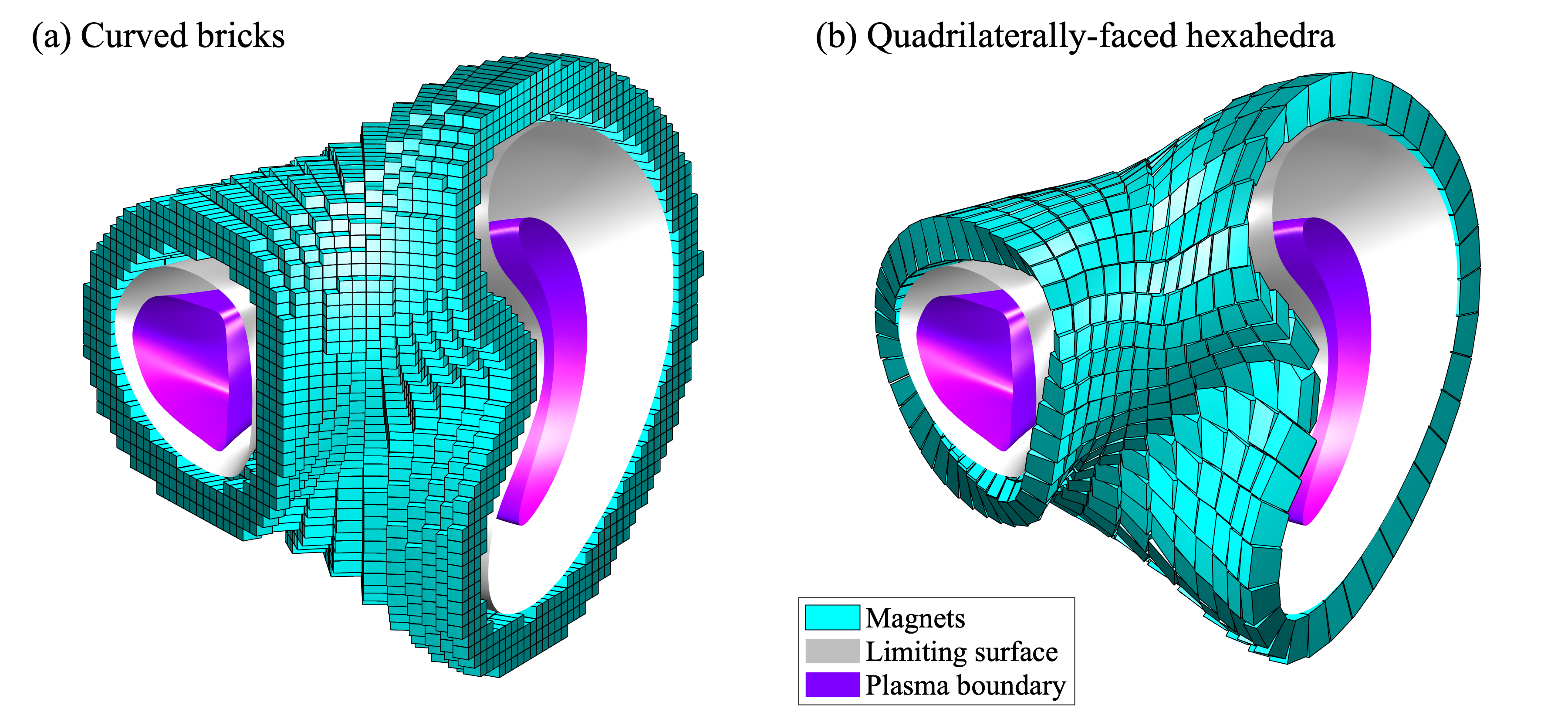
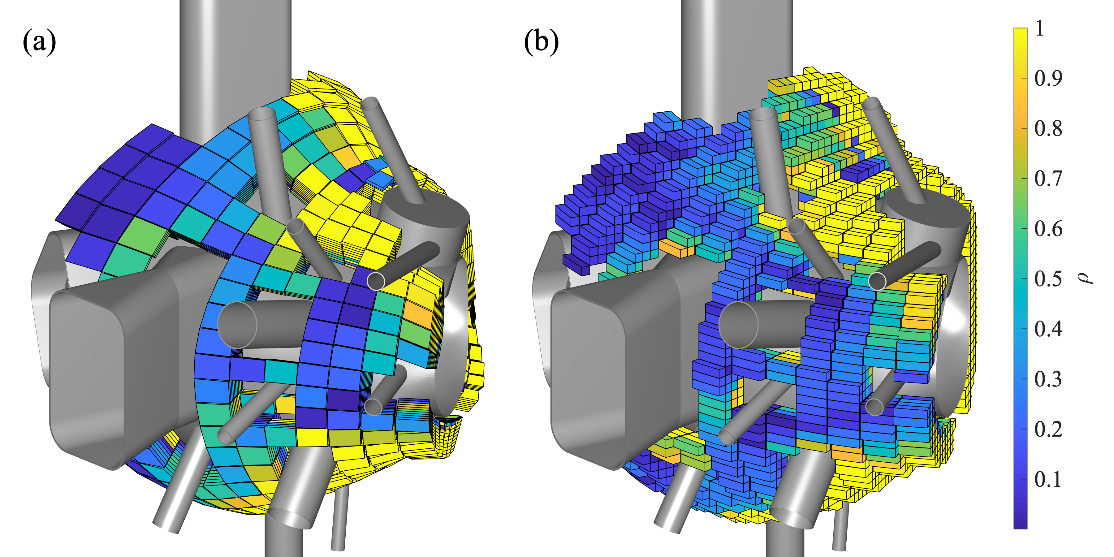
Fig. 1a shows an example configuration of curved bricks built around an NCSX-like plasma equilibrium. To construct a brick array for an experimental configuration, one first defines the brick size, gap spacing, and array bounds for each cylindrical dimension. From this initial grid, all bricks not entirely within a specified permissible volume are eliminated. This volume is defined as the space between two toroidal limiting surfaces: an inner surface that encloses the plasma, and an outer surface that encloses the inner surface. In the configurations we have explored to date, the inner limiting surface has conformed to the experimental vacuum vessel, and the outer limiting surface has been the locus of points whose closest distance to the inner surface in their respective poloidal plane is equal to a given radial extent.
One advantage of the curved-brick concept is its geometric simplicity. Since all bricks at a given radial position have the same shape, configurations of curved bricks will have relatively few unique magnet geometries. We note, however, that magnets of the same shape within an array will likely need to have many different polarization directions, dependent on their location relative to the plasma.
2.2 Quadrilaterally-faced hexahedra
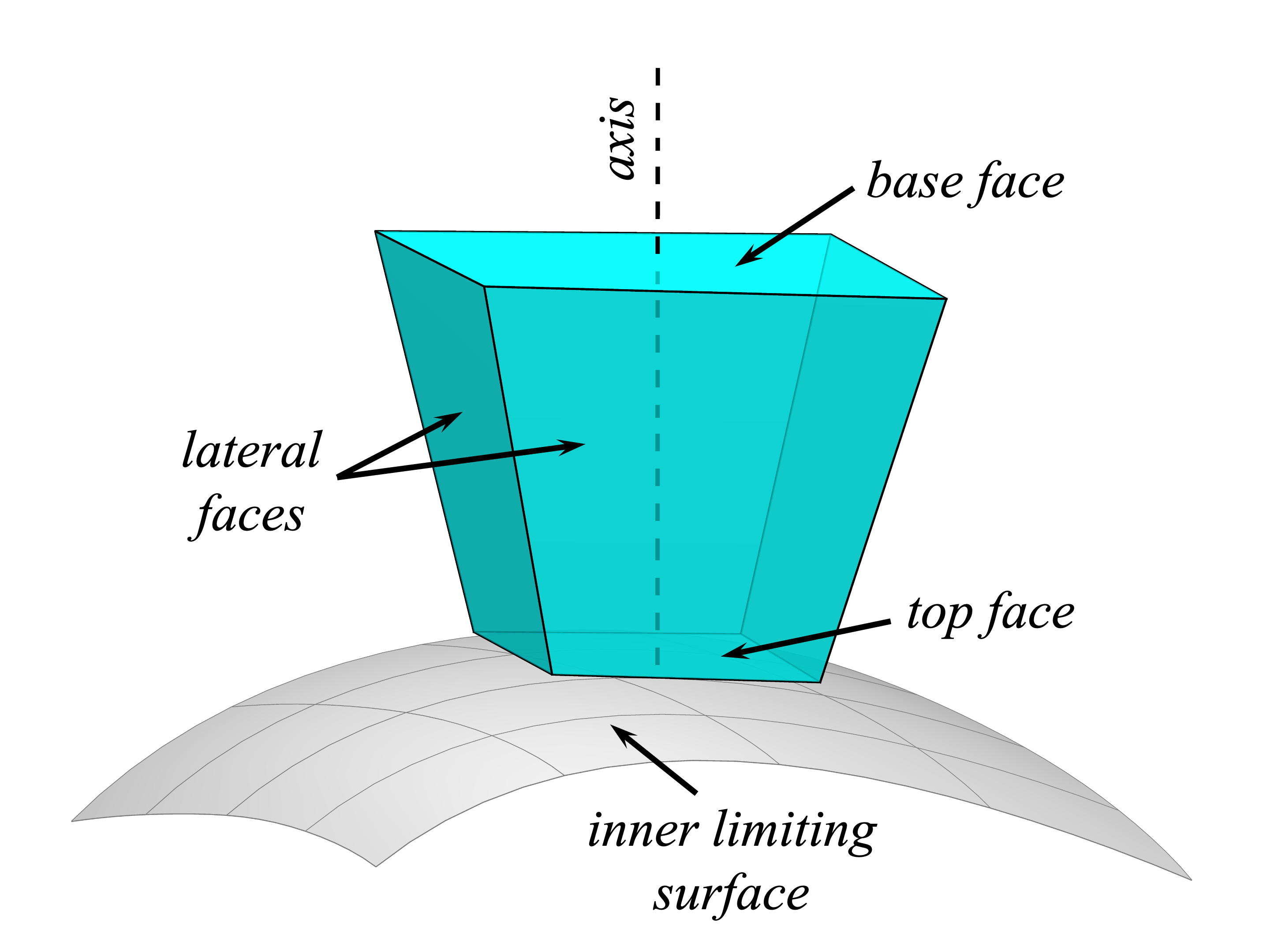
In the second geometric concept explored in this work, the magnets are constructed to conform closely to the plasma geometry. The magnets are placed in an irregular grid that wraps around the inner limiting surface and is partitioned into cells in the poloidal and toroidal dimensions. Each cell contains a magnet in the form of a quadrilaterally-faced hexahedron. A diagram of a hexahedral magnet is shown in Fig. 2. Each of the four lateral faces of a hexahedral magnet are parallel to the faces of the magnets in their respective adjacent grid cells. The top face (closest to the inner limiting surface) and base face (furthest from the inner limiting surface) are constrained to be parallel to one another. Each hexahedron is associated with a characteristic axis, a line that is perpendicular to the base and top faces. The hexahedra are positioned and aligned such that their axes are locally perpendicular to the limiting surface.
An exemplary array of quadrilaterally-faced hexahedra is shown in Fig. 1b. As demonstrated in this layout, the hexahedral geometry allows the magnets to fill the volume between the two limiting surfaces. Specifically, in regions where the inner limiting surface is convex (as is the case, for example, in Fig. 2), the cross-section of the magnet tapers along the axis from the base face to the top face. In regions where the inner limiting surface is concave, on the other hand, the magnet’s cross-section expands along its axis. This geometric concept is, in effect, a three-dimensional generalization of the assemblies of trapezoidal magnets in Halbach cylinders employed in particle accelerators and other applications [28].
In some grid cells in concave regions of the limiting surface, in particular on the inboard side near the “bean-shaped” plasma cross-section on the right of Fig. 1b, additional hexahedra are added to fill gaps between the original magnet layer and the inner limiting surface. A close-up view of a group of these additional hexahedra is shown in Fig. 17.
The concept of an array of magnets with axes oriented perpendicular to a toroidal surface was motivated by the study in Ref. [23], which demonstrated the physical feasibility of plasma confinement with a magnetized layer whose magnetization is locally perpendicular to a toroidal surface surrounding the plasma. The hexahedra are a discrete implementation of such a layer, assuming that the magnets are each polarized along their respective axes.
While the geometry of the hexahedral arrays is more complex than that of the curved bricks, they could in principle offer a degree of simplicity in their polarization requirements. If the magnets are all polarized along their axes (i.e. perpendicular to the base and top faces), they may be cut from slabs of magnetic material with uniform perpendicular polarization, thereby potentially reducing manufacturing complexity. Magnets with arbitrary polarization directions, by contrast, would likely require more time for machining and result in more discarded material.
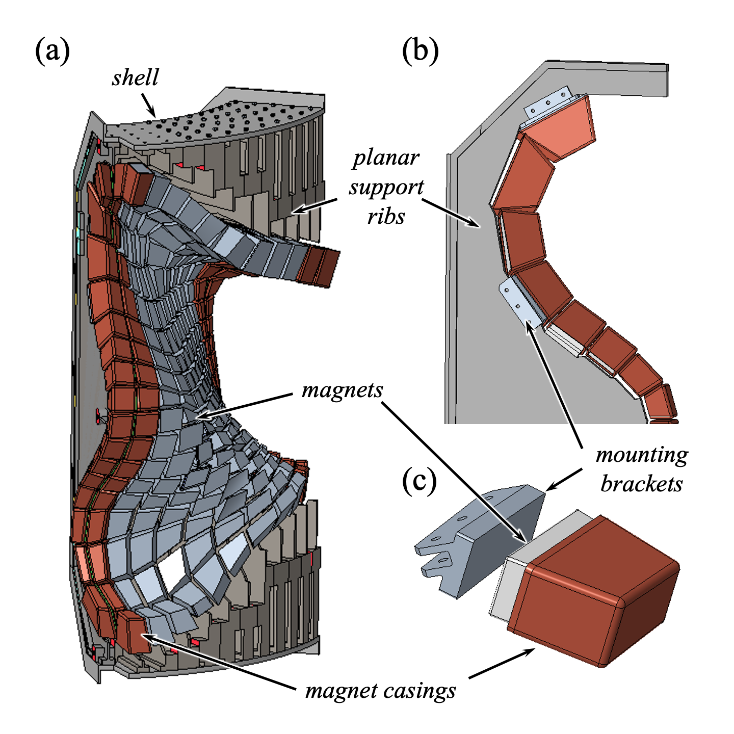
While the magnet axes are constrained to align with normal vectors to the limiting surface, the hexahedral concept still allows some freedom to choose the locations of the bases of the magnets within the grid to be convenient for mounting. In the hexahedral configurations explored to date, the magnet bases have been specified such that the bases in each poloidal row of the grid align to a constant toroidal angle. Thus, while the axes in a given grid row emerge from the bases in different directions dependent on the geometry of the inner limiting surface, the bases may all be mounted on planar external structures as shown in Fig. 3.
Further details on the algorithm for designing the hexahedral arrays are given in Appendix A.
3 Magnet arrays with normal polarization
The two magnet concepts introduced in Sec. 2 will be evaluated for suitability for a proposed variant of the NCSX stellarator. In each case, the magnets will replace the modular, non-planar coils of NCSX. The toroidal field is supplied by planar toroidal field (TF) coils. The target equilibrium is based on an optimized plasma configuration for NCSX. In absence of the modular coils, which would have contributed a substantial portion of the toroidal field, the capabilities of the TF coils alone limit the magnetic field strength 0.5 T. This is about one-third of the originally envisioned field [26]. The major characteristics of the target plasma equilibrium are summarized in Table 1.
| Major radius | 1.44 m |
|---|---|
| Minor radius | 0.32 m |
| (volume average) | 0.50 T |
| Rotational transform on axis | 0.35 |
| (volume average) | 4.1% |
| Toroidal current | 57 kA |
3.1 Optimization procedure
To determine the suitability of a given magnet array for this target plasma, we employed the Famus code, which optimizes the dipole moment of each magnet in order to match the required magnetic field for the target plasma [24]. Geometric magnet arrays were considered usable if a solution with sufficiently low residual field error could be found, subject to constraints on magnetization. For these optimizations, each magnet was represented as an idealized point dipole located at the magnet’s centroid. The maximum allowable dipole moment was capped at the magnet’s volume times a designated maximum bulk magnetization . For these studies, we have used , corresponding to the level presently attainable in rare-Earth magnets [15]. We note that, while the optimization procedure employed here produces arrays with continuous ranges of magnetization strength, an optimized magnet with a magnetization less than would be implemented in practice as a magnet with a magnetization of but with its dimensions reduced in order to preserve the optimized dipole moment.
Optimizations proceeded in two steps, both of which involved the minimization of objective functions with a quasi-Newton method as described in Ref. [24]. In the first step, the magnets, represented as dipoles, were initialized with a dipole moment of zero. The dipole moments were then optimized with the sole objective of minimizing the integral of the squared normal component of the magnetic field, , over the boundary of the target plasma. Here, is the net magnetic field, including contibutions from the magnets, toroidal field coils, and plasma, and is the unit normal vector on the plasma boundary. In the second step, the dipole moments output from the first step were refined in an optimization with two minimization objectives: the integral of and the sum of the squares of the dipole moments of each of the magnets. The goal of this refinement was to concentrate the magnetization within a smaller number of magnets within the arrangement and ultimately reduce the required volume of magnetic material for the array.
3.2 Scan of magnet layer thickness
The first magnet arrays tested for this target plasma consisted of hexahedral magnets (Sec. 2.2) with polarizations normal to the inner limiting surface. As such, the directions of the dipole moments in the Famus optimizations were fixed to be along the axes of the hexahedra, whereas the magnitudes were free to vary within the bounds permitted by . The polarity of the dipoles, i.e. whether their moments were parallel or antiparallel to the hexahedral axes, were also free to vary. The hexahedra were constructed around an inner limiting surface with the dimensions of the NCSX vacuum vessel [27, 29], which we note is not the same as the winding surface used to constrain the NCSX coils [30]. A minimum gap spacing of 2 cm was enforced between the magnets and the limiting surface. The minimum spacing between parallel faces of adjacent hexahedra was 0.5 cm, representing a highly optimistic estimate of the amount of room required between magnets for support infrastructure. In addition, each hexahedron was subdivided into 10 radially-arranged slices to enable greater spatial resolution of the required dipole moment distribution within the volume of the array. This is instructive, as each hexahedron in the array will likely consist of a subassembly of many smaller magnets.
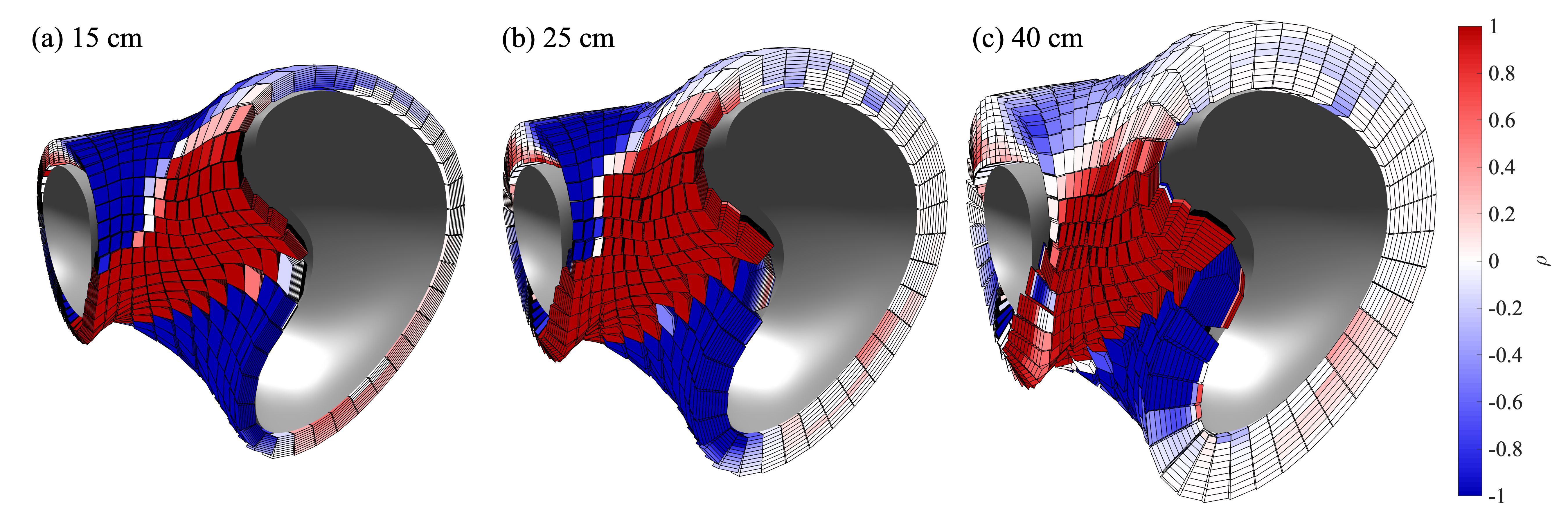
Each of the arrays had a distinct, uniform value of the radial extent parameter, ranging from 15 cm to 40 cm. Three of these arrays, having radial extents of 15 cm, 25 cm, and 40 cm, respectively, are shown in Fig. 4. The magnets are colored according to the optimized value of the density , defined as , where is the optimized dipole moment and is the magnet volume. In this figure, is given a positive sign if the optimized dipole moment points away from the limiting surface and a negative sign if the moment points toward the limiting surface. As indicated in the renderings, magnets on the inboard side tend to require greater strengths regardless of the array thickness. This is consistent with the findings in Ref. [24] and indicates that many of the magnets on the outboard side could be removed in further refinements of the arrays without much loss to the attainable magnetic field accuracy.
The general objective of the scans of magnet thickness was to identify the minimum thickness (correlated with magnet quantity) needed to produce the magnetic field required for the target plasma. The attainable field accuracy for a given magnet set is quantified here by surface average of the fractional normal component of the net magnetic field, . We find that values of tend to produce good agreement with the boundary, rotational transform profile, and effective ripple of the target plasma configuration, as will be shown later. We will therefore adopt this as an empirical criterion for determining whether a magnet arrangement can confine the target plasma.
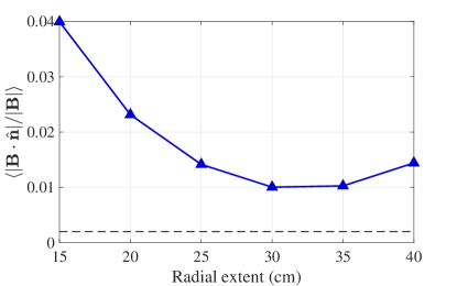
The values of attained for each of the magnet arrays in the thickness scan are shown in Fig. 5. As shown in the plot, none of the arrays tested exhibited , indicating that none were able to produce a sufficiently accurate magnetic field. The highest field error was observed in the thinnest array (radial extent of 15 cm), and the field error decreased substantially for the first few increments of the radial extent. Such a trend indicates that the thinnest arrays did not contain enough magnetic material to counterbalance the normal components of the field on the plasma boundary arising from the toroidal field coils and the plasma. However, simply adding magnets was not sufficient to reduce the field error to acceptable levels. This can be understood from the fact that incrementing the radial extent entails adding magnets that are further and further from the plasma, which therefore have less and less of an effect on the field at the plasma boundary. The increase in field error in the final increment is likely due to the presence of larger gaps between the magnets, which tend to be necessary to prevent overlaps between the corners of nearby magnets in thicker hexahedral arrays.
3.3 Scan of maximum magnetization
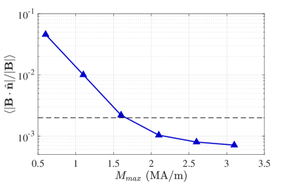
A second parameter scan with normally-polarized hexahedral magnets further supports the above interpretation. In this scan, the radial extent was fixed at 0.3 m, the value at which the smallest value of was attained in the first scan. The varied parameter in this case was , which ranged from 0.6 to 3.1 . As indicated in Fig. 6, the field error diminished substantially as increased, far below the level achievable through increasing the magnet layer thickness with fixed at 1.1 (Fig. 5).
The ability of the different magnet arrays in this scan to meet the physics requirements for plasma confinement was investigated through magnetohydronamic (MHD) equilibrium and neoclassical confinement calculations. We used the VMEC code [31, 32] to calculate free-boundary MHD plasma equilibria using the external fields provided by the NCSX toroidal field coils and each of the optimized magnet arrangements. In addition, the NEO code [33] was used to calculate , a metric of neoclassical confinement.
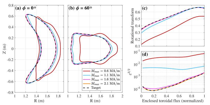
Results from these calculations for selected arrangements are shown in Fig. 7, including the equilibrium plasma boundary, rotational transform profile, and as compared to the corresponding data for the target plasma configuration. The agreement between the attainable and targeted plasma boundaries and parameter profiles for the arrangements with and was poor, particularly for the neoclassical transport. However, all properties converged toward the target as increased, with good agreement at and excellent agreement at . Since those latter two arrangements had values of of and respectively, we have chosen as an empirical criterion for adequate magnetic field accuracy when evaluating subsequent magnet arrangements.
While values of of 2.1 are far above the limitations of present-day materials, these results are instructive for the purposes of magnet array design. While arrays of magnets with normal polarization can in principle confine stellarator plasmas, they require high magnetic concentrations close to the plasma. For the target plasma explored here, normally-polarized magnet arrays cannot generate adequate confining fields—at least if they must be placed outside the NCSX vacuum vessel.
4 Magnet arrays with arbitrary polarizaion
4.1 Hexahedral thickness scan, revisited
The set of hexahedral arrays with varying radial extents first discussed in Sec. 3.2 was subjected to a second set of optimizations, this time allowing for the polarization direction to vary relative to the hexahedrons’ axes. The initial guess for the dipole moment in each case was a vector with magnitude zero parallel to the axis of the corresponding hexahedron. As before, was set at the rare-Earth magnet value of in each case. As shown in Fig. 8, the attainable values of were much lower than in the fixed-axis case. In particular, arrangements with radial extents as low as 17.5 cm were usable in the sense of attaining . Renderings of three arrangements from the scan, indicating the spatial distribution of optimized values, are shown in Fig. 9.
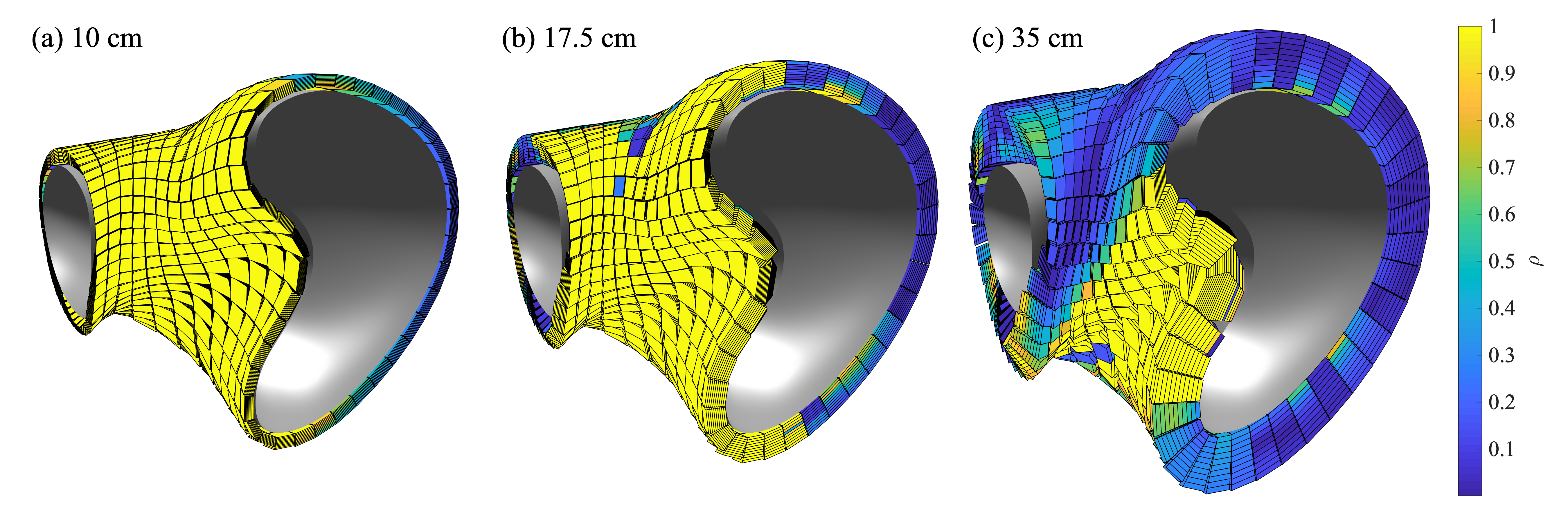
The importance of the freedom to decouple the magnetic moments from the normal direction is illustrated in the distribution of the optimized polarization directions. Fig. 10a shows a histogram of the cumulative dipole moment strength of the magnets, binned according to the angle between the optimized dipole axis and the axis of the corresponding hexahedral magnet body. An angle of corresponds to polarization along the hexahedron’s axis (i.e. locally normal to the limiting surface) in either the positive or negative direction, whereas an angle of corresponds to polarization perpendicular to the hexahedron’s axis (i.e. locally tangential to the limiting surface). The histogram corresponds to the optimized dipole moments of the arrangement with the lowest usable radial extent of 17.5 cm. For this arrangement the angular offset is distributed widely between normal and tangential.
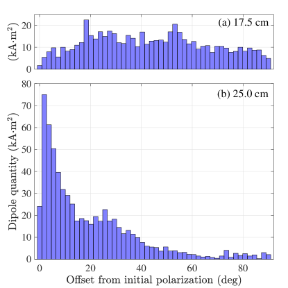
Thicker magnet layers admitted distributions that were more skewed toward the normal () orientation, as shown in Fig. 10b for the arrangement with a radial extent of 25 cm. However, note that this arrangement has a much greater total dipole quantity (exhibited by the sum over all bins), indicating that the array makes less efficient use of its magnet material in generating the required field. Furthermore, the distribution still has a finite spread, indicating the continued necessity for at least some magnets to have tangential components to their polarization despite the increased thickness.
4.2 Arrangements with curved-brick magnets
The results in Sec. 3.2 indicate that hexahedral magnet arrays with the simplifying constraint of normal polarization cannot adequately confine target plasma configuration. Rather, the magnet arrangement must have a tangential polarization in some regions and normal polarization in others. Since the potential simplicity of normally-polarized hexahedral magnets cannot be realized, the curved brick concept introduced in Sec. 2.1 could be preferable to the hexahedra due to its relative geometric simplicity.
Accordingly, a set of curved brick arrangements with differing values of radial extent was performed to identify possible arrangements. For each arrangement, the poloidal cross-section of each brick was a square with side lengths of 4.9 cm in the radial and vertical dimensions. Each brick subtended a toroidal angle of . Gap spacings of 0.1 cm were maintained between adjacent bricks in the radial and vertical dimensions, and in the toroidal dimension.
The geometric orientation of each curved brick is independent of the plasma geometry. As a result, the choice of initial guess for the magnetic polarization direction is not as intuitive as for the hexahedra, which have characteristic axes perpendicular to a toroidal surface around the plasma. In this study, two separate optimizations were performed for each arrangement of curved bricks. For the first optimization, the polarization direction of each brick was initialized to be along the radial unit vector—that is, , where and are unit vectors in the Cartesian and directions and the toroidal angle is evaluated at the brick’s centroid. For the second, the direction was initialized along a line originating from the brick and intersecting the inner limiting surface at a perpendicular angle. In this latter scheme, the spatial distribution of initial polarizations throughout the magnet volume is similar to that of an array of hexahedra initialized along their axes. In all cases, the dipole moment magnitude was initialized at zero and was constrained not to exceed .
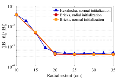
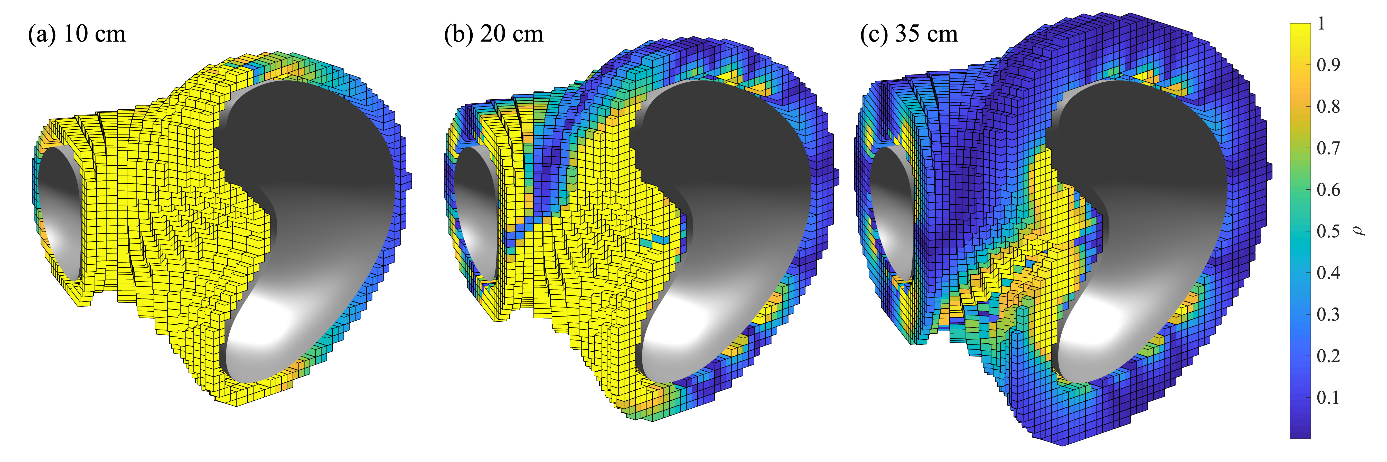
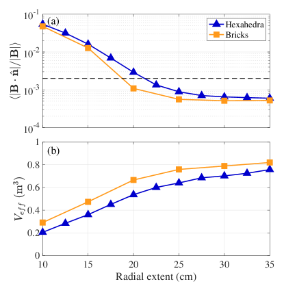
The values of attainable for each arrangement are plotted in Fig. 8. Note that the minimum radial extent required to meet the criterion , approximately 20 cm, was essentially the same for both initialization cases, and also quite similar for the scan of hexahedral arrangements. Three of the arrangements, along with their optimized values, are shown in Fig. 11. As with the hexahedral cases, the optimized dipole moment magnitude in thicker distributions becomes increasingly concentrated near the inboard side of the bean-shaped plasma cross-section.
One point of contrast between the two initialization schemes can be seen in the effective magnet volume, . We define as , where is the total number of magnets in the arrangement and is the optimized dipole moment of each magnet. provides an estimate of the volume of magnet material required to build the arrangement if magnets of low to intermediate optimized densities are substituted for smaller magnets with (i.e. magnetization equal to ). In general, lower values of are desirable and, as mentioned in Sec. 3.1, the second stage of each optimization sought to reduce this quantity (more precisely, ) while still maintaining good magnetic field accuracy.
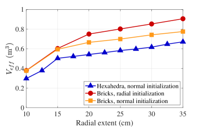
While the attainable appears to be fairly robust against differences in initalization and in the geometry of the individual magnets, this cannot be said for . As shown in Fig. 12, is at least 10% lower for magnets with the normal initialization than for magnets with the radial initialization, at least in the subset with sufficient field accuracy (radial extents of 20 cm or greater). Evidently, the solution obtained through the optimization is sensitive to some initial parameters, perhaps a result of local minima in the optimization space [24]. This sensitivity can have consequences for construction costs—in this case, the required magnet quantity.
Also of note are the values of obtained from the free-axis thickness scan of hexahedral magnet arrangements, also shown in Fig. 12. The hexahedral arrangements were able to obtain similar field accuracy with substantially lower volume than either set of optimizations for the curved bricks. It is hypothesized that this can be explained at least in part by the toroidally-conforming geometry of the hexahedra. Whereas the brick arrangements exhibit many wedge-shaped gaps near the inner limiting surface due to their rectangular cross-sections, the better-aligned hexahedra fill a larger fraction of the volume near the inner limiting surface, where magnetic material would have the most influence on the field at the plasma boundary.
5 Effects of spatial restrictions
5.1 Diagnostic ports
The magnet arrangements studied so far have all fully covered the limiting surface, corresponding to the NCSX plasma vessel. In a real device, of course, some of these magnets will need to be removed in order to make space for access ports for diagnostic, heating, and fueling systems.
To evaluate the impact of ports on magnet arrangements, two more sets of magnet arrangements were optimized, one with hexahedral geometry and the other with curved brick geometry, this time excluding magnets that collide with any of the ports foreseen for NCSX. Most of these ports lie on the outboard side of the plasma vessel. As in the previous parameter scans, each arrangement had a different value of the radial extent. The curved bricks were initialized with normal polarizations.
The attainable values and for the two parameter scans are shown in Fig. 13. The lowest radial extent for which hexahedral arrangements attained was 22.5 cm, 5 cm higher than the case without ports considered. Remarkably, the curved brick arrangements attained at the same radial extent as in the case without ports, although was about a factor of 2 higher. The 22.5 cm hexahedral arrangement had per half-period, whereas the 20 cm curved brick configuration had per half-period; hence, the discrepancy in between the hexahedral and brick arrangements was lower with all NCSX ports considered. Renderings of each of these arrangements are shown in Fig. 14.
5.2 Gaps for containment structures
All magnet configurations considered thus far have exhibited very small gap spacing between adjacent magnets (0.5 cm between the faces of adjacent hexahedra and 1 mm between the faces of adjacent curved bricks). However, the magnet mounting concepts presently under consideration require magnets to be enclosed in stainless-steel casings that are in turn mounted to external structures (Fig. 3). If such designs are ultimately adopted, larger gap spacings between magnets may be necessary in order to leave room for the walls of the casings.
Gap spacing requirements impact the amount of magnet material that can fill a layer of a given thickness. Hence, an increase in the minimum gap spacing would lead to a corresponding increase in the radial extent required for the magnets to produce an adequate confining field. This effect is quantified for the case of hexahedral magnets in Fig. 15, which shows the attainable versus radial extent for arrangements with increasing minimum gap spacings. The smallest value, 0.5 cm, was employed for the hexahedral arrangements studied in Sec. 3 and 4.
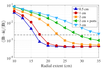
The first increment of the gap spacing, from 0.5 cm to 1 cm, requires a relatively small increase of approximately 2 cm in radial extent to satisfy the criterion for . Subsequent increments in the gap spacing require much larger increases in the radial extent, however: an increase from 1 cm to 2 cm in gap spacing calls for an increase of approximately 5 cm in radial extent, and an increase from 2 cm to 3 cm in gap spacing calls for an increase of more than 10 cm in radial extent. One factor driving the nonlinearity of this relationship is that 3 cm is comparable to the magnet size in some portions of the arrangement.
Also shown in Fig. 15 is a version of the arrangement with 2 cm gap spacing excluding magnets that overlap with the NCSX ports. As with the case explored in Sec. 5.1, the removal of these magnets results in an increase of the required radial extent, this time to 30 cm.
The above study indicates that the hexahedral arrangement under consideration is workable for gap spacings of up to at least 2 cm, which would leave ample room for each hexahedral magnet (or radial stack of magnets) to be enclosed in a casing with a standard wall thickness of 0.25 in (6.35 mm). To accommodate even larger gap spacing, it may be necessary to modify the parameters of the array; for example, by reducing the toroidal and poloidal grid cell resolution in order to boost the filling factor of magnet material between the limiting surfaces.
Although the analysis in this section focused on the case of hexahedral magnets, similar considerations would apply for arrangements of curved-brick magnets. We also note that one need not enforce large spaces between every brick, as multiple bricks may be grouped together within the same casing.
6 Conclusions and future work
In support of efforts to develop stellarators that employ arrays of permanent magnets for plasma confinement, we have developed the Magpie code to enable studies of different geometric concepts for magnets and facilitate rapid fine-tuning of the arrangements according to physics and engineering requirements. To date, two geometric concepts have been developed and studied: curved bricks, which align to an arbitrary cylindrical grid, and quadrilaterally-faced hexahedra, which conform closely to toroidal plasma geometry.
The hexahedral concept was designed as a discrete implementation of a magnetized layer with polarization constrained to be normal to a surface surrounding the plasma. However, it was found that the physical limitations on the strength of present-day rare-Earth magnets make it impossible for normally-polarized hexahedra to attain adequate field accuracy, at least for the targeted NCSX-like plasma configuration.
If the constraint for normal polarization is relaxed, however, both hexahedra and curved bricks are capable of confining the target plasma configuration with rare-Earth magnets. With both concepts, magnet layers conforming to the NCSX plasma vessel with thicknesses on the order of 20 cm were shown to be capable of generating adequate magnetic fields to confine the targeted plasma equilibria. For the hexahedral concept, an increase of 5 cm in radial extent is required if magnets are removed to make space for all of the NCSX ports. If larger gap spacings are required for magnet casings or other support structures, the minimum thickness will increase further. In the case of hexahedral magnets, usable magnet arrays were found for gap spacings of at least 2 cm.
The dipole moment distributions obtained by the optimizer had a noticeable dependence on both the geometric properties of the magnet arrangement and the initial conditions for the optimization procedure. Solutions for curved brick arrangements whose moments were initialized normally to the toroidal limiting surface generally had lower effective magnet volumes than those for which the moments were initialized along the radial unit vector. Furthermore, solutions for hexahedral arrangements tended to have lower effective volumes than solutions for curved brick arrangements. Thus, while brick-shaped magnets have the advantage of geometric simplicity, surface-conforming hexahedral magnets may admit configurations with lower overall magnet quantities.
The immediate application for this work is a stellarator experiment planned to be constructed at PPPL using components from the NCSX experiment, including the vacuum vessel and the toroidal field coils. However, Magpie has been developed to aid in the design of permanent magnet arrays for any stellarator configuration. This study has demonstrated the code’s ability to facilitate conceptual studies of different magnet geometries and to evaluate the trade-offs of different design choices.
The findings presented here represent just the first steps in developing a buildable permanent magnet array for a stellarator. Many critical questions remain to be addressed in determining the overall feasibility of applying permanent magnets to stellarators. This includes developing tolerance criteria for magnet fabrication—both for geometry and magnetization—and assessing the associated costs to maintain adequate field accuracy. In addition, modeling to date has not accounted for corrections to the magnetization of each magnet due to the presence of backgroud fields; prototype studies will be needed to determine the corrections. The mounting structures, of which some early concepts were shown in this paper (Fig. 3), must be qualified to withstand the forces on each magnet—preliminary estimates indicate that a typical hexahedral magnet will experience 5-10 kN due to the background magnetic field. Furthermore, the construction of a large array consisting of multiple metric tons of magnetic material will require the development of suitable tooling and assembly practices. Efforts are currently underway to construct a prototype magnet array in order to address these and other issues.
In support of these efforts, further refinements and additions to the Magpie code and the optimization approach are anticipated. One area of flexibility that we have not yet explored in depth would be to reduce the effective volume by allowing for nonuniformity in the thickness of the magnet layer, with thicker portions in the regions where large magnetic fields are required (particularly the inboard side) and thinner or nonexistent portions in less-critical areas. Additional geometric concepts may be implemented in Magpie depending on further research and development in magnet fabrication. In terms of the optimization, alternative techniques currently under consideration would constrain each magnet to have one of a few discrete polarization directions, rather than leaving the direction completely free as is the case in the continuous quasi-Newton method employed in this work. Such constraints could greatly simplify the fabrication requirements.
Finally, the target plasma configuration studied in this paper required a relatively thick magnet layer for good field accuracy despite its low average field strength of 0.5 T. This may call into question the utility of permanent magnets if the target configuration were to be scaled up to reactor-relevant parameters; in particular, with a much higher magnetic field. However, as discussed in Ref. [23], the target configuration studied here was designed with modular coils in mind, and we expect that it is possible to find alternative plasma configurations that would require less magnetic material for a given level of field strength. To this end, the Magpie code was designed to be relatively simple to include in optimization loops by codes such as Stellopt [34], which could be used to improve both the plasma equilibrium and the magnet array geometry in order to reduce the volume of magnets required for adequate confinement. Furthermore, as proposed in Ref. [7], it would also be worthwhile to investigate reactor concepts that use tilted planar coils or mildly non-planar coils in conjunction with permanent magnets, which may still be simpler to construct than conventional stellarator reactor designs that rely solely upon non-planar coils.
7 Acknowledgments
The authors would like to thank M. Zarnstorff and R. Mercurio for the helpful discussions. This work was supported by the US Department of Energy under contract number DE-AC02-09CH11466. The digital data for this pper may be found at https://dataspace.princeton.edu/jspui/handle/88435/dsp01pz50gz45g.
Appendix A Details on the design of hexahedral arrays
A.1 Base grid generation
The procedure for designing a hexahedral array in Magpie begins with the definition of the volume in which magnets are permitted, specified as the region between an outer toroidal limiting surface and an inner toroidal limiting surface. The outer surface must enclose the inner surface, and both are assumed to enclose the target plasma. To date, the inner surface has been supplied as a set of Fourier harmonics for the and coordinates as functions of poloidal angle and toroidal angle , and the outer surface has been implied through the definition of a uniform radial extent.
With the magnet volume thus defined, the magnet design proceeds by generating a base grid. The base grid consists of a two-dimensional array of vertices arranged on the outer limiting surface. Each set of four adjacent vertices defines a cell in which a magnet is to be placed. The base faces of each magnet are constrained not to extend behind any of its respective base grid vertices.
The vertices (and, by extension, the bases of the magnets) may be arranged to interface in a convenient way with their respective mounting structures. For the configuration shown in Fig. 1b, each poloidal row of magnets was intended to be mounted onto a planar support structure as shown in Fig. 3. In order for the bases of the magnets to line up along these planar structures, the vertex points in each poloidal row of the base grid were chosen to have the same azimuthal (toroidal) angle .
A.2 Definition of the bounding planes
Once the base grid is defined, the next step is to determine the bounding planes between adjacent magnets. Since the magnets are ultimately oriented such that their axes are perpendicular to the inner limiting surface, the bounding planes should also intersect this surface at a near-perpendicular angle. To ensure this, the base grid vertices are first projected onto the inner limiting surface such that each projection line intersects the surface normally. This is accomplished by solving the system of three nonlinear equations,
| (1) |
for , , and . Here, and are the poloidal and toroidal angles, respectively, of the projected point on the inner limiting surface from which a perpendicular projection line intersects the vertex point . The axis of this line is the unit normal vector to the inner limiting surface , and is the distance along the axis from to . The solution to these equations is not necessarily unique, especially for vertex points near concave regions of the limiting surface, so it is important to supply reasonable initial guesses of , , and to ensure continuity in the projection lines associated with adjacent vertex points.
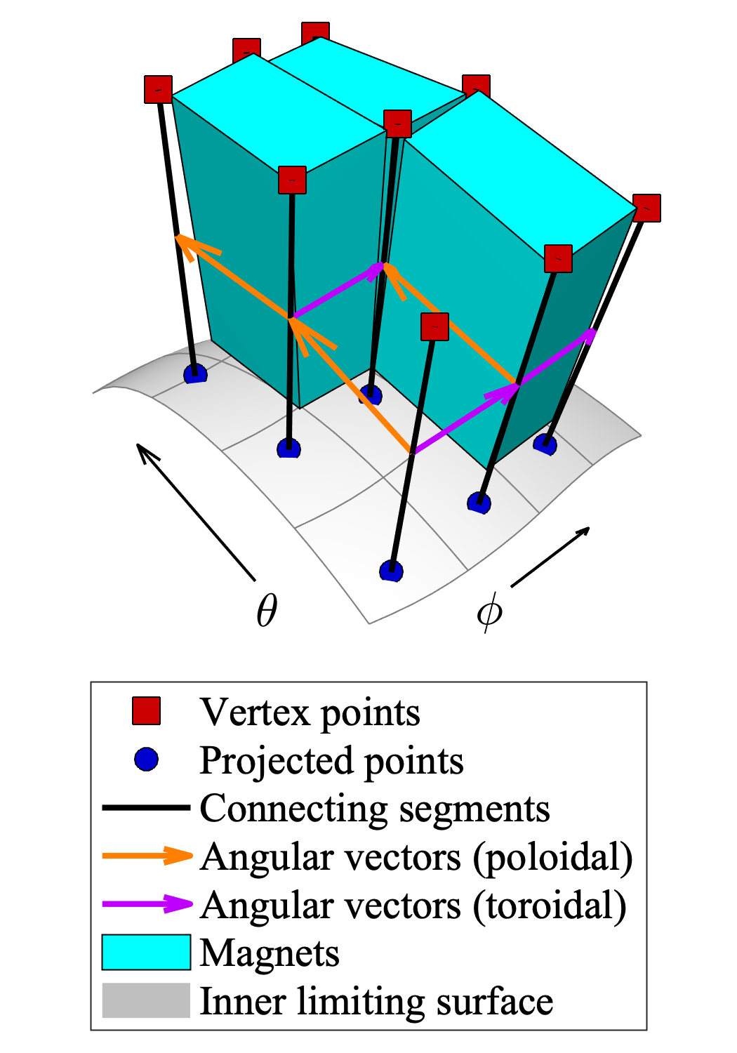
The key reference points and directions for determining the bounding planes are illustrated in Fig. 16. Each pair of vertex points, projected points, and connecting segments demarks a boundary between adjacent grid cells and is thus used to determine the corresponding bounding plane. The normal vector of each bounding plane is derived from the cross-product of an angular vector (a vector between the midpoints of the connecting segments), and the radial vector (derived as an average of the axes of the connecting segments). The plane is fixed to a reference point whose coordinates are calculated by averaging the coordinates of the vertex and projected points. Some boxcar smoothing may be applied to neighboring angular vectors, radial vectors, and plane reference points in order to avoid sharp transitions between adjacent bounding planes.
With the bounding planes between adjacent grid cells defined, the lateral faces of the hexahedral magnets within the grid cells are then determined. The normal vector of each lateral face is that of the nearest bounding plane, and the plane of the face is offset by a specified distance into the grid cell to enforce a finite gap spacing between the (parallel) face of the adjacent magnet. The planes of each of the four lateral faces intersect to form four radial edge lines.
The magnet’s axis is determined from the normal vector of the inner limiting surface at the average poloidal and toroidal angles of the four projected points on the surface at the corners of its grid cell. The axis also defines the normal vectors of the top and base faces. The top face is positioned to maintain a minimum separation distance from the limiting surface. The base face is positioned not to not have a greater elevation than any of the grid cell’s vertex points along the magnet axis.
Following this procedure, each hexahedron will not collide with its four nearest neighbors due to the constraint that adjacent faces be parallel. However, it is still possible for overlaps to occur with other nearby hexahedra, especially those across corners in the grid. If such overlaps are detected, the lateral faces of the overlapping hexahedra are iteratively withdrawn inwards until the overlap is resolved.
Depending on the input settings such as grid resolution, radial thickness, and limiting surface geometry, it is possible for the above procedure to result in over-constrained hexahedra with undesirable or erroneous properties. These could include, for example, opposite faces that intersect one another. Magnets with such undesirable properties are identified and eliminated from the output set. Since this will leave gaps in the magnet grid, it is advisable to adjust the input settings to minimize the number of erroneous hexahedra.
A.3 Concave regions
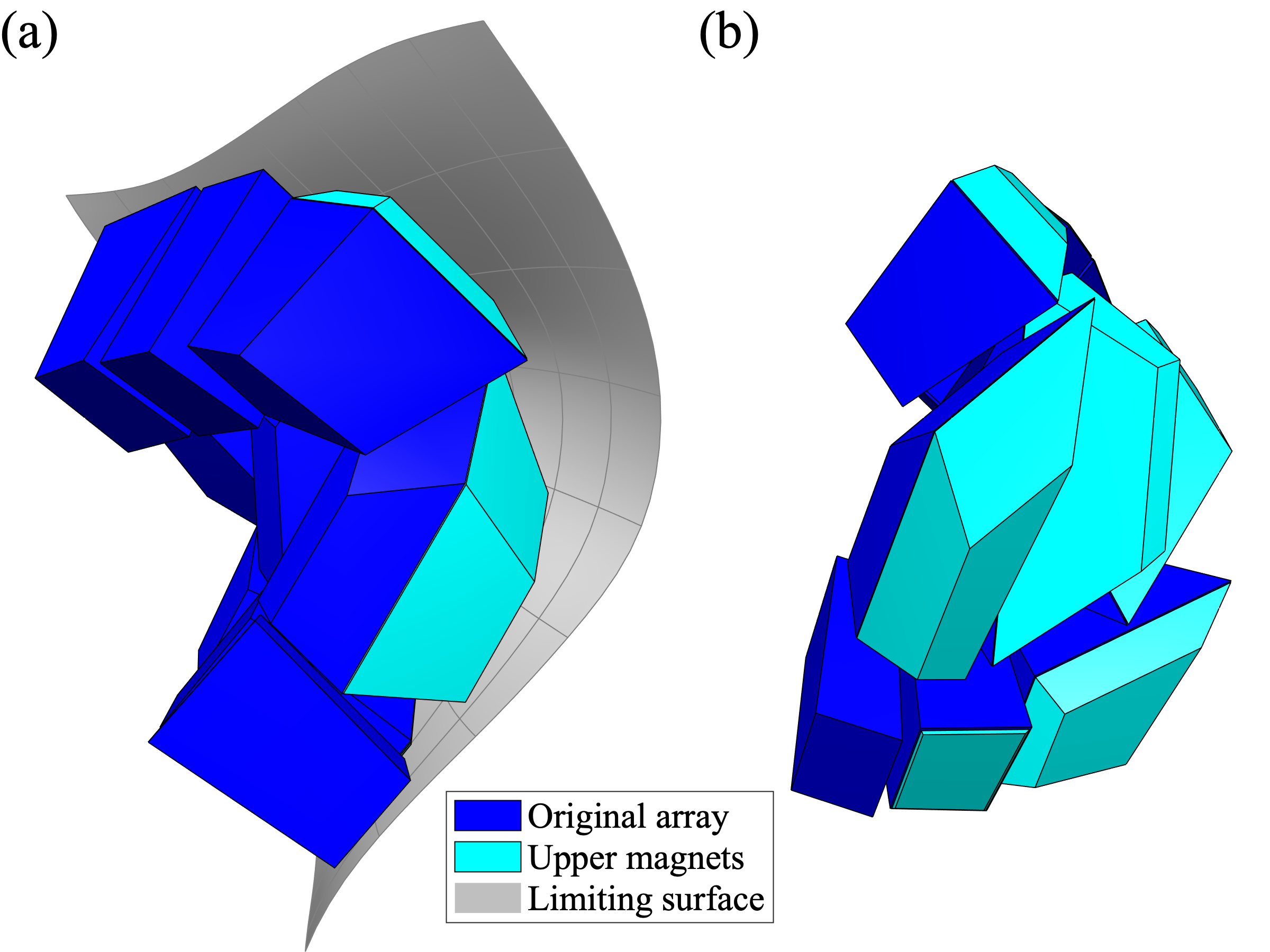
In concave regions of the limiting surface, it is possible that significant gaps could arise between the surface and the top face of the hexahedral magnet. To fill this volume, the code offers the option to add an “upper” hexahedral magnet between the original magnet and the vessel. Examples of such upper magnets are shown in Fig. 17. The upper hexahedron’s base face coincides with the original hexahedron’s top face, and the upper hexahedron tapers along the axis as it expands into the concave region of the limiting surface.
References
- [1] H. E. Mynick. Transport optimization in stellarators. Physics of Plasmas, 13:058102, 2006.
- [2] C. Beidler, G. Grieger, F. Herrnegger, E. Harmeyer, J. Kisslinger, W. Lotz, H. Maassberg, P. Merkel, J. Nührenberg, F. Rau, J. Sapper, F. Sardei, F. Scardovelli, A. Schlüter, and H. Wobig. Physics and engineering design for Wendelstein VII-X. Fusion Technology, 17:148, 1990.
- [3] J. Sapper and H. Renner. Stellarator Wendelstein VII-AS: physics and engineering design. Fusion Technology, 17:62, 1990.
- [4] F. S. B. Anderson, A. F. Almagri, D. T. Anderson, P. G. Matthews, J. N. Talmadge, and J. L. Shohet. The Helically Symmetric Experiment (HSX): goals, design and status. Fusion Technology, 27:273, 1995.
- [5] P. Merkel. Solution of stellarator boundary value problems with external currents. Nuclear Fusion, 27:867, 1987.
- [6] M. Landreman. An improved current potential method for fast computation of stellarator coil shapes. Nuclear Fusion, 57:046003, 2017.
- [7] P. Helander, M. Drevlak, M. Zarnstorff, and S. C. Cowley. Stellarators with permanent magnets. Physical Review Letters, 124:095001, 2020.
- [8] A. Aleksandrov and A. Menshov. Magnet design for the SNS Laser Stripping Experiment. In Proceedings of the 5th International Particle Accelerator Conference, Dresden, Germany, page TUPRO117, 2014.
- [9] P. A. Thonet. Use of permanent magnets in multiple projects at CERN. IEEE Transactions on Applied Superconductivity, 26:4101404, 2016.
- [10] G. Hoffstaetter, D. Trbojevic, and C. Mayes. CBETA Design Report. Technical Report BNL-114549-2017-IR, Brookhaven National Laboratory, 2017.
- [11] Z. Q. Zhu and D. Howe. Halbach permanent magnet machines and applications: a review. IEEE Proceedings - Electric Power Applications, 148:299, 2001.
- [12] C. W. Roberson and P. Sprangle. A review of free-electron lasers. Physics of Fluids B, 1:3, 1989.
- [13] F. H. O’Shea, G. Marcus, J. B. Rosenzweig, M. Scheer, J. Bahrdt, R. Weingartner, A. Gaupp, and F. Grüner. Short period, high field cryogenic undulator for extreme performance x-ray free electron lasers. Physical Review Special Topics - Accelerators and Beams, 13:070702, 2010.
- [14] B. Blümlich, J. Perlo, and F. Casanova. Mobile single-sided NMR. Progress in Nuclear Magnetic Resonance Spectroscopy, 52:197, 2008.
- [15] C. Benabderrahmane, P. Berteaud, M. Valléau, C. Kitegi, K. Tavakoli, N. Béchu, A. Mary, J. M. Filhol, and M. E. Couprie. Nd2Fe14B and Pr2Fe14B magnets characterization and modelling for cryogenic permanent magnet undulator applications. Nuclear Instruments and Methods in Physics Research A, 669:1, 2012.
- [16] J.-P. Wang, N. Ji, X. Liu, Y. Xu, C. Sánchez-Hanke, Y. Wu, F. M. F. de Groot, L. Allard, and E. Lara-Curzio. Fabrication of Fe16N2 films by sputtering process and experimental investigation of origin of giant saturation magnetization in Fe16N2. IEEE Transactions on Magnetics, 48:1710, 2012.
- [17] Y. Jiang, M. Al Mehedi, E. Fu, Y. Wange, L. Allard, and J.-P. Wang. Synthesis of Fe16N2 compound free-standing foils with 20 MGOe magnetic energy product by nitrogen ion-implantation. Scientific Reports, 6:25436, 2016.
- [18] G. H. Nielson, C. O. Gruber, J. H. Harris, D. J. Rej, R. T. Simmons, and R. L. Strykowsky. Lessons learned in risk management on NCSX. IEEE Transactions on Plasma Science, 38:320, 2010.
- [19] T. Rummel, K. Riße, G. Ehrke, K. Rummel, A. John, T. Mönnich, K.-P. Buscher, W. H. Fietz, R. Heller, O. Neubauer, and A. Panin. The superconducting magnet system of the stellarator Wendelstein 7-X. IEEE Transactions on Plasma Science, 40:769, 2012.
- [20] H.-S. Bosch, R. C. Wolf, T. Andreeva, J. Baldzuhn, D. Birus, T. Bluhm, T. Bräuer, H. Braune, V. Bykov, A. Cardella, F. Durodié, M. Endler, V. Erckmann, G. Gantenbein, D. Hartmann, D. Hathiramani, P. Heimann, B. Heinemann, C. Hennig, M. Hirsch, D. Holtum, J. Jagielski, J. Jelonnek, W. Kasparek, T. Klinger, R. König, P. Kornejew, H. Kroiss, J. G. Krom, G. Kühner, H. Laqua, H. P. Laqua, C. Lechte, M. Lewerentz, J. Maier, P. McNeely, A. Messiaen, G. Michel, J. Ongena, A. Peacock, T. S. Pedersen, R. Riedl, H. Riemann, P. Rong, N. Rust, J. Schacht, F. Schauer, R. Schroeder, B. Schweer, A. Spring, A. Stäbler, M. Thumm, Y. Turkin, L. Wegener, A. Werner, D. Zhang, M. Zilker, and et al. Technical challenges in the construction of the steady-state stellarator Wendelstein 7-X. Nuclear Fusion, 53:126001, 2013.
- [21] J. Alderman, P. K. Job, R. C. Martin, C. M. Simmons, and G. D. Owen. Measurement of radiation-induced demagnetization of Nd-Fe-B permanent magnets. Nuclear Instruments and Methods in Physics Research A, 481:9, 2002.
- [22] M. Landreman et al. Calculation of permanent magnet arrangements for stellarators. In preparation.
- [23] C. Zhu, M. Zarnstorff, D. Gates, and A. Brooks. Designing stellarators using perpendicular permanent magnets. Nuclear Fusion, 60:076016, 2020.
- [24] C. Zhu, K. C. Hammond, M. Zarnstorff, T. Brown, D. Gates, K. Corrigan, M. Sibilia, and E. Feibush. Topology optimization of permanent magnets for stellarators. Nuclear Fusion, in press [preprint: https://arxiv.org/abs/2005.05504].
- [25] C. Zhu, S. R. Hudson, Y. Song, and Y. Wan. New method to design stellarator coils without the winding surface. Nuclear Fusion, 58:016008, 2018.
- [26] M. C. Zarnstorff, L. A. Berry, A. Brooks, E. Fredrickson, G.-Y. Fu, S. Hirshman, S. Hudson, L.-P. Ku, E. Lazarus, D. Mikkelsen, D. Monticello, G. H. Neilson, N. Pomphrey, A. Reiman, D. Spong, D. Strickler, A. Boozer, W. A. Coopern, R. Goldston, R. Hatcher, M. Isaev, C. Kessel, J. Lewandowski, J. F. Lyon, P. Merkel, H. Mynick, B. E. Nelson, C. Nührenberg, M. Redi, W. Reiersen, P. Rutherford, R. Sanchez, J. Schmidt, and R. B. White. Physics of the compact advanced stellarator NCSX. Plasma Physics and Controlled Fusion, 43:A237, 2001.
- [27] B. E. Nelson, L. A. Berry, A. B. Brooks, M. J. Cole, J. C. Chrzanowski, H.-M. Fan, P. J. Fogarty, P. L. Goranson, P. J. Heitzenroeder, S. P. Hirshman, G. H. Jones, J. F. Lyon, G. H. Nielson, W. T. Reiersen, D. J. Strickler, and D. E. Williamson. Design of the national compact stellarator experiment (NCSX). Fusion Engineering and Design, 66-68:169, 2003.
- [28] K. Halbach. Design of permanent multipole magnets with oriented rare Earth cobalt material. Nuclear Instruments and Methods, 169:1, 1980.
- [29] F. Dahlgren, P. Goranson, and P. Titus. Structural analysis of the NCSX vacuum vessel. Fusion Science and Technology, 47:926, 2005.
- [30] N. Pomphrey, L. Berry, A. Boozer, A. Brooks, R. E. Hatcher, S. P. Hirshman, L.-P. Ku, W. H. Miner, H. E. Mynick, W. Reiersen, D. J. Strickler, and P. M. Valanju. Innovations in compact stellarator coil design. Nuclear Fusion, 41:339, 2001.
- [31] S. P. Hirshman and J. C. Whitson. Steepest-descent moment method for three-dimensional magnetohydrodynamic equilibria. Physics of Fluids, 26:3553, 1983.
- [32] S. P. Hirshman, W. I. van Rij, and P. Merkel. Three-dimensional free boundary calculations using a spectral Green’s function method. Computer Physics Communications, 43:143, 1986.
- [33] V. V. Nemov, S. V. Kasilov, W. Kernbichler, and M. F. Heyn. Evaluation of 1/ neoclassical transport in stellarators. Physics of Plasmas, 6:4622, 1999.
- [34] S. A. Lazerson, J. Schmitt, C. Zhu, J. Breslau, and STELLOPT Developers. STELLOPT. https://doi.org/10.11578/dc.20180627.6, 2020.