All femtosecond optical pump and X-ray probe: holey-axicon for free electron laser
Abstract
We put forward a co-axial pump(optical)-probe(X-rays) experimental concept and show performance of the optical component. A Bessel beam generator with a central 100 m-diameter hole (on the optical axis) was fabricated using femtosecond (fs) laser structuring inside a silica plate. This flat-axicon optical element produces a needle-like axial intensity distribution which can be used for the optical pump pulse. The fs-X-ray free electron laser (X-FEL) beam of sub-1 m diameter can be introduced through the central hole along the optical axis onto a target as a probe. Different realisations of optical pump are discussed. Such optical elements facilitate alignment of ultra-short fs-pulses in space and time and can be used in light-matter interaction experiments at extreme energy densities on the surface and in the volume of targets. Full advantage of ultra-short 10 fs X-FEL probe pulses with fs-pump(optical) opens an unexplored temporal dimension of phase transitions and the fastest laser-induced rates of material heating and quenching. A wider field of applications of fs-laser-enabled structuring of materials and design of specific optical elements for astrophotonics is presented.
-
17
May 2020
Keywords: X-rays, Free electron laser (FEL), ultra-short phenomena, pump-probe, warm-dense matter, astrophotonics, co-axial volumetric interaction diagnostics
1 Introduction
This is a concept and perspective paper that discusses the readiness of two different technologies for a new era in ultra-fast femtosecond (fs) pump-probe experiments. We highlight the need for new optical elements that can accommodate a simpler handling of fs-pump and fs-probe beams at vastly different wavelengths: an optical fs-pump at visible nm and X-ray fs-probe at 0.12398 nm (10 keV) [1].The temporal and spatial overlap of ultra-short pulses is always a challenge, especially when the focal spot is m, while the axial extent of a fs pulse is only m. This is an even greater challenge when the beams are propagating at an angle to each other towards the interaction region, which makes the effective interaction zone extend only a fraction (projection) of the length of the pulse (along the axis of symmetry) depending on their diameter . A front tilt of the beam can be introduced to have the maximum overlap as it would be for the case [2] for the interfering fs-pulses at large angles using diffractive optical elements (DOEs).
Nonlinear optical interactions are usually used to determine the temporal overlap of the optical pulses. At high intensity and irradiance (the time average flow of energy per unit time per unit area [W/cm2]) of optical or X-ray pulses, when structural modification of the focal region occurs by ablation, phase transition, and/or color center formation in dielectrics, high precision spatial and temporal overlap of pulses is simplified and achieved by optical monitoring of the interaction zone. Transmitted and reflected beams are used for the final optimisation. In the case of hard X-rays ( keV) which have a small absorption cross section within materials, timing with fs-laser pulses (optical) can be achieved by detection of increased transmissivity of GaAs under fs-X-ray pulse [3]. A LiF crystal was used for in situ control of focal position of few-keV X-ray free electron laser (X-FEL) [4] beam and for measurement of a transverse beam intensity profile with a spatial resolution of 1 m [5].
There is an inherent benefit to use axially extended beams such as Bessel-Gauss beams rather those with a Gaussian cross-section. For a co-linear propagation of optical and X-ray pulses their interaction volume can be augmented and spatial-temporal alignment simplified. Obviously, a central hole in an optical element is required for on-axis propagation of the fs-X-ray pulse. Since the focus of a fs-X-ray free electron laser (X-FEL) is tunable by the placement of the sample along the beam with the smallest spot area of m2 (at Spring-8 facility; Spring-8 Angstrom Compact free electron Laser, referred to as SACLA), a hole of 100 m diameter would meet the requirements of alignment tolerances. The optical fs-pump will be delivered onto the target by a flat axicon lens -mm-diameter, which is typical for free-space beam of most of fs-lasers, and is inscribed around the central hole. This concept of an axially elongated Bessel beam intensity delivered by the on-axis converging conical wave can have several realisations using refocusing and demagnification with a 4f-optical system (see discussion further in the text) or reflective optics to facilitate actual optical-pump X-ray-probe experiments. Recent developments in fs-laser fabrication of flat optical elements have produced a mature technology which is utilised for this demonstration of a new optical element inscribed in a typical pure-silica blank of 3 mm thickness.
Here, we show the principle of needle-beam intensity generation by using flat optics by fs-laser inscription, which is a feasible method for fabrication of optical elements. Then a Bessel-beam generator is demonstrated by controlled patterning with nanoscale form-birefringence. The very same fs-laser inscription was used for fabrication of the central hole in the optical element by fs-laser induced breakdown and chemical wet etching [6, 7, 8]. The fabricated optical element is characterised and discussion of its applicability for X-FEL experiments is presented, based on a recent demonstration of ns-pump (optical) and fs-probe (X-FEL) study of laser-induced compression of corundum [9]. We discuss the prospects for probing matter under ”warm-dense” conditions [10, 11] when the potential energy of the interaction between electrons and nuclei and the kinetic energy of electrons are of the same magnitude (as in the interior of planets). Ultra-fast solid-liquid-gas-plasma transitions and subsequent quenching of materials into new exotic phases can be monitored with unprecedented temporal resolution using X-ray diffraction (XRD) [9].
2 Making optics flat for faster laser inscription
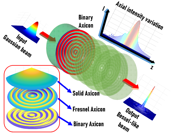
One obvious simplification of lens fabrication and increase in the fabrication throughput is to make optics flat by inscription of the required refractive index pattern for the light-ray bending function (e.g., a curved surface of a lens). Combination of refractive and diffractive functions can be used for specific optical elements, e.g., the function of a conical lens (axicon) can be achieved by a Fresnel axicon [12] or a binary circular grating. The circular grating can convert a Gaussian beam or a uniform illumination into a Bessel-like beam [13]. The conversion of a Gaussian beam into a Bessel-like beam using a circular grating is shown in Fig. 1. A binary axicon is the simplest possible realization of an axicon. A solid axicon and a Fresnel axicon can function either as a refractive element or a diffractive element depending upon the features involved. Contrarily, a binary axicon is a pure diffractive element. This discussion of refractive vs diffractive optics is important in regards to optical losses and efficiency of the optical element when high irradiance has to be reached at the focus (on the target); see Sec. 4.
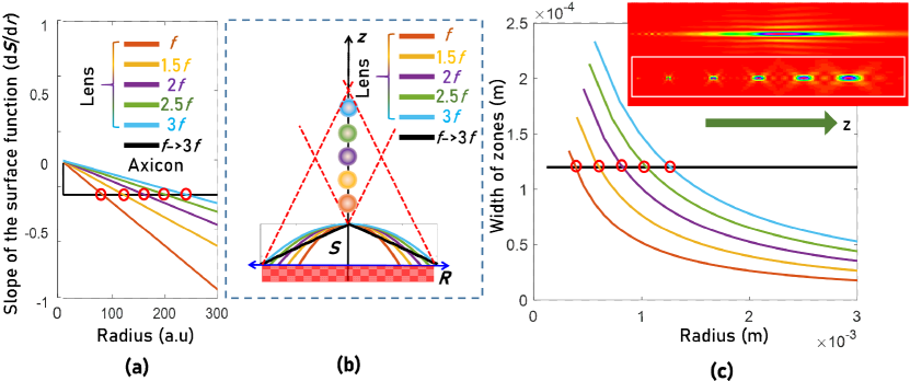
There are numerous perspectives to understanding light modulation by an axicon [14, 15, 16] and a different perspective is presented here. A solid axicon’s surface profile is linear with respect to the radial coordinate given by , where is the base angle and . The surface of a lens is given by (paraxial approximation), where is the focal length of the lens. A lens collects all the incident light at different values of the radial coordinate and focuses it on a point with the entire radial coordinate mapped to a single point in space when . Contrarily, an axicon maps every value of the radial coordinate to a different point on the optical axis, focusing light rings with different radii at different locations on the optical axis. The result is a large focal depth and self-reconstructing behaviours [17]. In a way, an axicon can be considered as a collection of infinitesimal rings of lenses of different focal lengths stacked along the radial coordinate. To prove this, the two surface functions and are differentiated with respect to the radial coordinate and plotted for five values of focal length of lenses to in steps of in Fig. 2. From the Fig. 2(a), it is seen that the slope values of the lenses meet the constant slope value of the axicon at different regions. Stronger(faster) lenses meet sooner than the weaker(slower) ones. The surface functions are also plotted for reference in Fig. 2(b).
The same analogy applies to diffractive lenses and axicons except that the beam modulation is achieved using diffraction rather than refraction in the above cases [18]. As the refraction angles are controlled by the surface profile of the refractive elements, the diffraction angles are controlled by the width of the zones. A diffractive axicon has a fixed period while the period of the Fresnel zone lenses vary with the radial coordinate given by , where is order of the zones. Again comparing an axicon’s period with that of a Fresnel zone lens (Fig. 2(c)), it is seen that the width of the zones meet the period of the axicon at different radial values extending the earlier analysis to diffractive domain. The light modulation by a diffractive axicon and a Fresnel zone lens ( to in steps of ) were simulated using scalar diffraction formulation with Fresnel approximation as a convolution between the complex amplitude of an axicon given by ) or that of a Fresnel zone lens given by ) with a Quadratic phase function with a complex amplitude ) as shown in an inset in Fig. 2. When the complex amplitude of a Fresnel zone lens is convolved with that of a quadratic phase function, both with the same focal distances, a delta-like function is generated indicating that light is focused on a point. On the other hand, when the complex amplitude of an axicon is convolved with the quadratic phase function, a part of the above two functions are conjugates of one another (crossing points in Fig. 2(b)) generating a delta light function (central peak of the Bessel function), while the other parts contribute to the rings around the central peak upon convolution. For different axial distances, different radial regions of the axicon matches with the conjugate of the corresponding quadratic phase functions resulting in a central peak with the uncompensated radial regions contributing to the rings formation around the central peak. When the two diffractive functions are binary, then there are slight deviations corresponding to the higher diffraction orders.
Engineering of refractive index pattern using fs-laser inscription for a specific optical function (e.g., defined by a 3D surface of a lens/axicon) can be used for fabrication of a simple flat lens which is described next.
3 Fabrication of holey-axicon
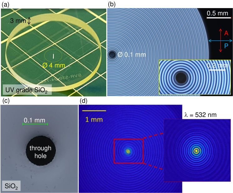
Figure 3 shows an axicon with central 0.1-mm-diameter hole for the optical (pump) and X-ray (probe) using ultra-short 25 fs X-FEL. Collinear (co-axial) propagation geometry facilitates spatial overlap of the laser ablation/modification zone to be probed with on-axis X-FEL 10 keV fs-pulse for fast imaging of phase transitions and material excitation undergoing the dielectric-to-metallic transition with a fast changing Die-Met state of permittivity [19].
The 4-mm-diameter ( mm) lens was inscribed by fs-laser pulses in hours. The central hole was also made by fs-laser damaging of \ceSiO2 host with subsequent wet etching in basic solution [6, 7, 8]; all together it took 6 hours. Fabrication was carried out on a commercial fs-fabrication station (WOP-Workshop of Photonics), an integrated solution of fs-laser (Pharos, Light Conversion) with linear stages (Aerotech). Polarisation of fs-pulse was set linear with a controlled azimuth .
The refractive index change induced in silica is approximately due to form-birefringence [20] and has an axial extent for retardance of at 530 nm wavelengths (or waveplate), hence m. The entire cylindrical volume of m3 and the speed of fabrication was m3/min. Considering that approximately only a half of the volume was laser structured the final speed of laser fabrication for the axicon (without central hole) was m3/min ( mm3/min). This high value was achieved because there was a small number (up to 3) of focal position (depth) re-focusings required for axial stitching which can be made perfectly aligned as reported earlier [21]. For fs-laser inscription of damaged regions for through-hole etching, it was necessary ten times refocusing along optical axis for the entire 3 mm thickness of silica blank.
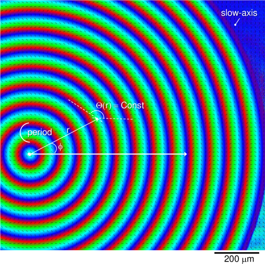
Figure 4 shows detailed slow-axis orientation map of the form-birefringent nanogratings in silica. The slow axis is perpendicular to the nanograting planes which defined the form birefringence , where is the extraordinary (along the optical axis) and is the ordinary indices, respectively [22]. The local azimuth of nanogratings was only dependent on the radial position and was independent on the polar orientation (this condition makes an orientation-independent optical element). Various optical elements for manipulation of spin and orbital momenta of light can be designed based on this principle where both propagation and geometrical phases are invoked to control intensity, phase, and polarisation [23]. The width of the zone with particular azimuth of nanogratings can be flexibly controlled as well as the axial extent of the fs-inscribed gratings. This provides flexibility to engineer axial intensity distribution and its extent which can be understood from discussion on Fig. 2. Fs-laser inscription of refractive index modifications can be made for almost loss-less conditions in terms of light absorption and only light scattering is a cause of some () transmission losses at visble 400 - 700 nm window. Recently, the scattering is further reduced in silica glass [24].
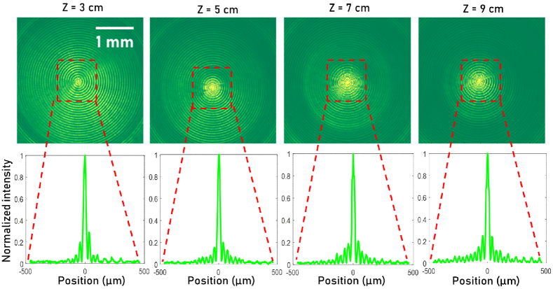
The diffraction patterns recorded at distances of 3 cm, 5 cm, 7 cm and 9 cm and the corresponding intensity profiles are shown in Fig, 5. The diameter of the central on-axis intensity was m at -intensity maximum. Centimeters long Bessel-like beam propagation is due to large apex angle of .
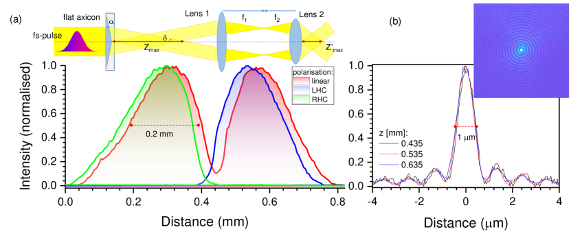
Demagnification of the lateral and axial extent of the Bessel beam can be carried out using 4f-optical setup as shown in Fig. 6. The factor of was applied resulting in focal volume with approximately m diameter (Fig. 6(b)) and axial extent of 0.2 mm at FWHM. The form birefringence due to nano-gratings is inscribed in silica with an azimuthally rotating pattern and corresponds to the -waveplate condition. This manifests in polarisation insensitivity of the axial intensity distribution (Fig. 6(a)). There is a difference in leading and trailing slope of the intensity envelope which can be explored in ionisation of the target. Moreover, fs-pulses can be tailored with specific frequency chirp which also contributes to the control of ionisation; red-shifted wavelengths are usually leading the shorter wavelengths (a positive chirp) as schematically shown in the inset of (a). The demonstrated demagnification of Bessel beam down to diameter m is favorable to exceed the required irradiance of TW/cm2 for dielectric breakdown of dielectrics (sapphire [28], olivine [29], silica [30] and glasses [31]) by only nJ (on target) pulses of fs duration for Gaussian beam and about J for the entire length of the Bessel pulse for discussed here holey-axicon. Tight focusing of fs-Bessel pulses into focal spot with lateral cross section well defines the axial modification inside, e.g., crystalline sapphire [32], without formation of nanogratings and confines structural modification directly along optical axis.
The possibility of controlling the axial intensity envelope by polarisation of the incident light shown for the linear and circular cases can be explored further using elliptically polarised optical pump. Elliptically polarised light is a sum of linearly and circularly polarised contributions providing a well-controlled tunability of the local intensity and its polarisation along the axis in the target. Another feature of an optical excitation by fs-pump using holey-axicon is presence of of the pulse energy on optical axis. This creates a condition of pre-excitation of the target since the Bessel part of the beam arrives at an angle with the optical axis. The delay between the side-ray (Bessel beam) and the Gaussian on-axis component can be estimated from the Snell’s law where is the refractive index of axicon (silica), is the base angle of axicon. Hence, the length of the hypotenuse is longer than the cathetus (at the angle ) by . For the conditions shown in Fig. 6 with the beam demagnified by factor , the delay of of the pulse length will occur; the angle with axis is increasing as . The Bessel-beam component contributes to the resonance absorption mechanism [33] and can create more efficient energy deposition along optical axis. Recent experiment with long ns-pulse Gaussian optical excitation at SACLA showed detailed time evolution of metallic Ta target spalation by XRD monitoring [34].
The optical pump delivery to the target and co-axial combination of their propagation should be solved considering a specific experimental chamber [9], however it will only be discussed below in terms of the basic concept. In this section we showed the possibility to use fs-laser inscription to fabricate a flat axicon and its performance to reach small lateral diameters (high irradiance) for prolonged axial length of 0.2 mm which elevates tolerances in target-beam alignments. Fs-laser irradiation and wet etching used to make a hole in the flat axicon can be readily used for drilling holes in glass plates used as mirrors for co-linear pump-probe combinations. Micro-holes can also be used to to hold target materials such as polymers, liquid crystals, or liquids for excitation by fs-Bessel pump beam. Metal-coated glass plates with micro-holes are expected to serve as beam alignment aids for both optical and X-FEL beams and can be fabricated via the demonstrated fs-laser fabrication-assisted wet etching.
4 Discussion: feasibility of fs-pump(optical) and fs-probe(X-FEL)
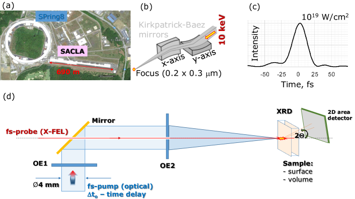
Combining optical fs-pump and X-FEL fs-probe is a very promising technique for investigation of light-matter interactions with tens-of-fs temporal resolution and spatial resolution down to few micrometers. Hard X-rays at 10-12 keV at X-FEL (SACLA) do not require a vacuum enclosure for pump-probe experiments which is always a practical advantage for setting up measurements. Noteworthy, vacuum can be used to avoid air breakdown in front of target or at focal points of 4f-optical setup (a negative lens can be used to avoid real focal point with additional advantage for shorter 4f-setup). Targets up to 100 m thickness are transparent to the X-FEL (SACLA) beam and interaction of fs-pump(optical) with target in the volume can be monitored by XRD. Co-axial pump-probe alignment is favorable for such experiments due to larger volume of interaction/characterisation. Previous studies of micro-void formation inside volume of transparent target were shown after a tightly focused single fs-laser pulse irradiation were structurally and optically investigated (post mortem) after its formation [36, 37, 35]. In situ measurements of void-formation using all-optical fs-pump-probe has a technical limitation due to challenges to focus on the micro-volume of the light-matter interaction zone with two bulky objective lenses at a normal to each other alignment [38, 39, 40]; the working distances of objective lenses with numerical aperture are 0.1-0.3 mm. With a micro-focus of X-FEL beam, probing of the micro-volume of light(optical)-matter interaction at the focal volume has no technical limitation rather a standard micro-precision task of beam alignment. Figure 7 shows SACLA facility [41], schematics of X-FEL focusing into sub-1 m focal spot [25], temporal profile of the fs-X-ray pulse at 10 keV and the concept of proposed experiment with holey-axicon (Fig. 3). The concept drawing has a generic meaning of light delivery onto a target and its actual realisation can be very different adopted to the actual beamline chamber [9] and is expected to have 4f-optical setup (inset of Fig. 6(a)) with central holes in lenses. It is noteworthy, that those holes will not deteriorate re-focusing and demagnification of Bessel beam since the light pulse is handled at its doughnut intensity distribution after the axicon. The folding point of optical and X-ray path will be carried out by a mirror with a hole which is a simple fs-fabrication task (Fig. 3). Also a reflection from mirror coating onto negative axicon with a central hole can even further simplify co-axial combination of pump and probe.
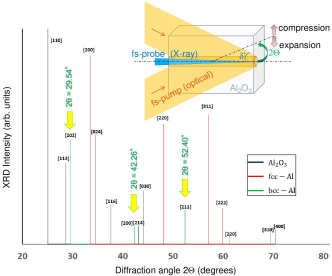
The experimental concept outlined in Fig. 7(d) has capability to detect structural modifications using readily available XRD instrumentation developed for SACLA beamlines [41, 27] with temporal overlap between 10 fs X-ray probe and optical IR fs-pump solved [42]. Feasibility to increase the volume of shock-wave compressed region in sapphire by approximately 200 times using focused Bessel-beam as compared with a tightly focused Gaussian beam was validated based on existing experimental evidence [33]. High pressure and temperature conditions in an ionised crystalline sapphire would cause separation of Al and O ions with quenching of the affected micro-volume into an amorphous phase with inclusions of bcc-Al nanoparticles tens-of-nm in size [35]. Figure 8 shows the expected angular positions of fcc and bcc-Al [43, 44] which are in the range of detectable angles at SACLA beamline.
Surface modification of non-transparent targets can be also investigated with the proposed method. Versatility of this technique can be further augmented with use of additional optical elements (OEs) for shaping pump-beam light intensity distribution or adding extra optical monitoring functions. For example, an OE with dual Fresnel lens plane wave generation can be multiplexed with a conical wave which produces a hologram on the monitoring CCD (added to setup in transmission or reflection). Such a hologram can be used to retrieve the phase and amplitude information from the interaction zone [45]. This technique is a single-shot and has 3D spatial and spectral resolution. A toolbox of X-ray optics for X-FEL applications becomes richer with possibility to generate X-ray vortex beams using fs-laser fabricated glass spiral plates [46]. Also, transient grating induced by X-ray X-FEL and probed by light or X-ray beam was proposed and conceptually tested [47]. Shearing interferometry was demonstrated for in situ characterisation of the wavefront of coherent X-FEL beam in the focal region [48].
5 Warm-dense matter (WDM) conditions: 100 eV at solid density plasma
It was demonstrated during the past decade that ultra-short intense laser pulse tightly focused deep inside a transparent dielectric generates the energy density in excess of several MJ/cm3 (energy per volume is pressure 1 MJ/cm3 = 1 TPa). Such energy concentration with extremely high heating and quenching rates leads to unusual solid-plasma-solid transformation paths overcoming kinetic barriers to formation of previously unknown high-pressure material phases [33, 36, 37, 35, 49] some of which can be predicted by ab initio modeling [50]. These discoveries were made with the pulse of Gaussian shape in space and in time. It was shown recently that the Bessel-shaped pulse transforms much larger amount of a material and allegedly creates higher energy density than was achieved before [51, 52]. This makes fs-Bessel pulses promising for creation and characterisation of warm dense matter (WDM) conditions [10, 11].
A prominent example of a high pressure material is metallic hydrogen \ceH2 predicted back in 1935 [53]. In addition to the profound fundamental interest in the metallic state of this most simple element, it has been suggested that it could be the most powerful rocket fuel yet to exist [54] or to exhibit superconductivity at room temperature [55]. Predictions suggest that once formed at extreme pressures in excess of 300 GPa ( GPa is at the Earth’s center), it can be recovered metastably to ambient conditions. Thus, it may not only be possible to harness these potentially transformative properties but also to potentially study such metallic \ceH2 ex situ after its creation. Smaller pressures GPa are required to form polymeric solid state \ceCO2 which could be retrieved to ambient contitions [56].
For research of high-pressure and high-temperature phases it is equally important their retrieval to lower pressure or ambient conditions. Again, ultra-short laser pulses with small volumes are important due to feasibility of ultra-fast thermal quenching which is required to recover metastable material which can also can be stabilised when is in the form of nanocrystals [35]. Formation of glasses from pure metals is a long-standing goal because they exhibit attractive mechanical properties such as high strength, elasticity and processability. Fundamental understanding of the glass transition is still lacking and is one of the open quests in physics. The very first monoatomic matallic glass was demonstrated when thermal quenching of nano-wires was achieved [57, 58]. Metastable amorphous \ceAl2O3 was produced by tightly focused single fs-pulse irradiation of crystalline sapphire [28]. Even bio-crystal silk can be quenched into its water soluble amorphous form due to small volume and fast quenching [59]. Consequence of nonlinear propagation and fillamentation of fs-Bessel pulses and their collapse causing bead-like traces of structural modification in glass [60] could be revealed with temporal XRD imaging and answer fundamental questions of nonlinear light propagation at strong electronic excitation. Apart from fundamental interest, such understanding would advance applications in laser dicing, drilling, cutting and large volume ablation [61, 62, 63, 7]. Research of high-pressure and high temperature phases of materials as well as WDM conditions would benefit basic science and applications from the concept outlined in this memorandum. Optical pump with fs-laser Bessel beam combined with synchronised X-ray probe with exceptional optical flux, sub-micron beam size, rather high X-ray photon energy in the keV-range and ultrashort pulse length 10 fs, allows one, to investigate the atomic motion via X-ray diffraction with extremely high spatial and temporal resolution. Recently emerging of X-FELs with pulse duration of 10–25 fs and the photon energy 8 keV currently available at the European X-FEL at DESY in Germany, with up to 17 keV to be expected in near future at the LCLS at the SLAC National Acceleration Laboratory in US, and with 7–15 keV at the SACLA at the RIKEN SPring-8 center in Japan are the ideal sources to be used as a probe pulse to uncover the processes of formation of unusual transient material states in the conditions far from thermodynamic equilibrium.
6 Outlook for fs-laser produced micro-optics: instrumentation for astronomy
We showed in the previous discussion that the very same fs-laser material modification is a ready method for fabrication of specific optical elements for tight focusing with added micro-holes for specialised X-FEL optics. The challenge there was to have flexibility for fs-inscription of efficient (low scattering losses and high form birefringence) optical elements which are 1-mm-diameter and to use the same fs-irradiation for the laser-assisted wet etching of a center-hole in the same design.
Astrophotonics is an application field of micro-optics where the efficiency of light collection (tight focusing at high transmissivity) is of paramount importance. Large numbers of millimetre-scale lenses are required for applications including multi-object fibre spectroscopy, where light is coupled in to hundreds to thousands of single fibres to collect light from many astronomical sources at once over a wide field, and integral field spectroscopy where lens arrays couple light in to integral field units (IFUs) based on image slices or fibre arrays [64]. Multi-object single fibre spectroscopy has a wide range of science applications including the fundamental physics of the Universe [65]. Use of optical fibres allows for less demanding spectrograph construction for wide-fields. Integral field spectroscopy allows detailed spatially resolved measurements of a wide variety of objects; studies of galaxies in particular are a major application [66].
Use of micro-optics allows changes in focal ratio, to optimally feed fibres to reduce focal ratio degradation [67] and to allow a contigous focal plane for IFUs [68]. Future instruments [69] will need a wide-angle (high-NA) aberration-free collection and broad UV-IR spectrum collection capability (i.e. high-performance antireflection coatings) for thousands of micro-lenses. Moreover, solutions for deployment of such instruments in a demanding environment with high thermal fluctuations should be developed. A solution is to integrate all optics into a single block (silica) and use micro-optics. Integration of surface relief lenses, which can be made aspheric for optimised light collection at different wavelengths, with inscribed optical elements as demonstrated in this concept study, provides a promising avenue. Optical fibers can be fixed at the geometrical focus using silica-based resists which have high transparency comparable with fused silica [70]. Fiber mounting ports can be etched out for fiber fixation by the very same method shown here for fabrication of the central hole in the axicon lens. Fs-laser assisted cleaving of optical fibers has been demonstrated to deliver smoother surfaces with a median tilt angle approximately 3 times smaller than conventional mechanical fiber cleavers [71]. This shows that fs-lasers can be used for inscription of optical elements inside the volume of silica or to form surface lenses, to define chemically etched micro-volumes and used for fiber cleaving.
An obvious extension of a single readout port design would consist of a micro-lens array (front) with inscribed optics (middle) and fiber connectors (back). When fixed in an Invar housing, such integration has the benefit of avoiding problems with matching the thermal expansion coefficients of multi-component lenses. Arrays of microlenses on the front surface can be made by fs-laser ablation combined with wet etching and high temperature surface finishing [72, 73, 74, 75]. Hybrid solutions with polymerised optical elements by fs-laser polymerisation [76] used together with inscribed light collection lenses are also possible, however this deserves a separate and wider discussion. Here we show, that fs-laser fabrication is a ready technology to be utilised in a wide field of applications and can be most effective when the diameter of optics is sub-1-mm (at the current 2020 state-of-the-art).
For a spectrally wide window of operation, optimisation of anti-reflective coatings, lens shape and refractive index profiles will require function specific design (see details in Appendix). The use of form-birefringent nanogratings in silica allows flexible refractive index engineering with the benefit of low scattering losses up to UV wavelengths [24], a spectrally broad functionality, and use of geometrical (Pancharatnam-Berry [77]; Fig. 4) and propagation phase control. The current method of nanograting recording in silica shown in Fig. 4 caused a small transmissivity decrease to 85% at 350 nm wavelength after annealing (without anti-reflective coatings). Structural defects induced by nanograting formation in silica can be thermally annealed without change to their form-birefringence [20] and temperatures up to 1150 ∘C (for 3 hours) were used for silica without erasing optical memory bits [78]. Nanogratings can also be recorded in crystalline sapphire, which has an even broader spectral window of transmission into the IR spectral range as compared to silica, and a very high (metal-like) thermal conductivity [79]. It was shown that instead of self-organised formation of nanogratings, form-birefringence of can be inscribed in a deterministic way down to 100 nm periods in sapphire [79]. Fs-laser fabrication can be used for lens definition on the surface and in the volume of glass (and crystal) as well as laser irradiation assisted wet etching for fabrication of all-in-glass integrated micro-optics and inter-connects with optical fibers.
7 Conclusions
We introduced the concept of a co-axial pump(optical)-probe(X-ray) diagnostic technique based on XRD developed at SACLA. It was shown that a fs-laser writing technique for flat optical elements can inscribe the required optical function of an axicon lens (a vortex beam can also be achieved; see Appendix) and can produce a well defined micro-hole for the on-axis combination of optical and X-FEL beams. The estimates provided here show that irradiance in excess of the breakdown of any dielectric ( TW/cm2/pulse) are achievable along the axial extension of the Bessel-pulse and therefore lead to structural modifications inside the volume of an optically transparent target. With higher order Bessel beams that have a doughnut intensity distribution in the lateral cross section (see Appendix), it is possible to create an implosion scenario by fs-pump(optical) with X-ray probing of densified material on-axis. The use of ultra-short fs-pulses for both excitation and probing will be able to reveal the intricacies of phase transitions and formation of new materials. The presented discussion is specifically based on the SACLA X-FEL but is applicable to any pump(optical)-probe(X-ray) beamline. The recent demonstration of a narrower eV and six times more spectrally bright X-FEL (SACLA) beam by self-seeding of the self-amplified spontaneous emission in the FEL [80] will increase the sensitivity of detection of structural changes of materials under fs-pump(optical). The concept discussed here is also applicable to other fields, e.g. astronomical instrumentation, where 3D surface lenses can be combined with micro-otical inscribed elements in silica for UV-IR imaging and spectroscopy and all made by fs-laser fabrication.
Acknowledgements
This research was funded by the ARC Discovery DP170100131, DP190103284, Linkage LP190100505 and JST CREST JPMJCR19I3 grants. This work was partially supported by the JSPS Japan-Australia bilateral collaboration program, the MEXT Q-LEAP program (grant no. JPMXS0118070187), and Genesis Research Institute, Inc (Konpon-ken, Toyota). Support of operational costs of Nanotechnology facility by Swinburne University of Technology (in 2016-19) is acknowledged. We are grateful to the Australian Institute of Nuclear Science and Engineering (AINSE) for facilitation of this study. Discussions of pump-probe experiments with Dr. Takeshi Matsuoka are gratefully acknowledged.
References
References
- [1] D. Pile, “First light from SACLA,” Nat. Photonics 5(8), p. 456–457, 2011.
- [2] T. Kondo, S. Matsuo, S. Juodkazis, and H. Misawa, “A novel femtosecond laser interference technique with diffractive beam splitter for fabrication of three-dimensional photonic crystals,” Appl. Phys. Lett.. 79(6), pp. 725–727, 2001.
- [3] T. Sato, T. Togashi, K. Ogawa, T. Katayama, Y. Inubushi, K. Tono, and M. Yabashi, “Highly efficient arrival timing diagnostics for femtosecond X-ray and optical laser pulses,” Appl. Phys. Express 8, p. 012702, 2015.
- [4] B. McNeil and N. R. Thompson, “X-ray free-electron lasers,” Nat. Photonics 4(12), p. 814–821, 2010.
- [5] P. Mabey, B. Albertazzi, T. Michel, G. Rigon, S. Makarov, N. Ozaki, T. Matsuoka, S. Pikuz, T. Pikuz, and M. Koenig, “Characterization of high spatial resolution lithium fluoride X-ray detectors,” Rev. Sci. Instrum. 90, p. 063702, 2019.
- [6] A. Marcinkevicius, S. Juodkazis, M. Watanabe, M. Miwa, S. Matsuo, H. Misawa, and J. Nishii, “Femtosecond laser-assisted three-dimensional microfabrication in silica,” Opt. Lett. 26(5), pp. 277–279, 2001.
- [7] S. Juodkazis, K. Yamasaki, V. Mizeikis, S. Matsuo, and H. Misawa, “Formation of embedded patterns in glasses using femtosecond irradiation,” Appl. Phys. A 79(4-6), pp. 1549 – 1553, 2004.
- [8] S. Matsuo, Y. Tabuchi, T. Okada, S. Juodkazis, and H. Misawa, “Femtosecond laser assisted etching of quartz: microstructuring from inside,” Appl. Phys. A. 84(1 – 2), pp. 99 – 102, 2007.
- [9] Y. Inubushi, T. Yabuuchi, T. Togashi, K. Sueda, K. Miyanishi, Y. Tange, N. Ozaki, T. Matsuoka, R. Kodama, T. Osaka, S. Matsuyama, K. Yamauchi, H. Yumoto, T. Koyama, H. Ohashi, K. Tono, and M. Yabashi, “Development of an experimental platform for combinative use of an XFEL and a high-power nanosecond laser,” Appl. Sci. 10, p. 2224, 2020.
- [10] S. Chang, “Extreme heating with an x-ray free-electron laser,” Physics Today 68(5), p. 18, 2015.
- [11] P. Drake, “High-energy-density physics,” Physics Today 63(6), p. 28, 2010.
- [12] I. Golub, “Fresnel axicon,” Opt. Lett. 31, pp. 1890–1892, 2006.
- [13] G. Gervinskas, G. Seniutinas, A. Vijayakumar, S. Bhattacharya, E. Jelmakas, A. Kadys, R. Tomašiūnas, and S. Juodkazis, “Fabrication and replication of micro-optical structures for growth of GaN-based light emitting diodes,” in Proc. SPIE 8923, Micro+Nano Materials, Devices and Applications, J. Friend, ed., p. 89234L, 2013.
- [14] J. McLeod, “The axicon: A new type of optical element,” J. Opt. Soc. Am. 44, pp. 592–597, 1954.
- [15] G. Scott and N. McArdle, “Efficient generation of nearly diffraction-free beams using an axicon,” Opt. Eng. 31, p. 2640–2643, 1992.
- [16] Y. Kizuka, M. Yamauchi, and Y. Matsuoka, “Characteristics of a laser beam spot focused by a binary diffractive axicon,” Opt. Eng. 471, p. 053401, 2008.
- [17] Z. Bouchal, J. Wagner, and M. Chlup, “Self-reconstruction of a distorted nondiffracting beam,” Opt. Commun. 151, p. 207–211, 1998.
- [18] A. Vijayakumar and S. Bhattacharya, Design and Fabrication of Diffractive Optical Elements with MATLAB, ch. 1. SPIE, Bellingham WA, USA, 2017.
- [19] E. Gamaly and A. Rode, “Ultrafast re-structuring of the electronic landscape of transparent dielectrics: new material states (Die-Met),” Appl. Phys. A 124(3), p. 278, 2018.
- [20] C. J. de Jong, A. Lajevardipour, M. Gecevicius, M. Beresna, G. Gervinskas, P. G. Kazansky, Y. Bellouard, A. H. A. Clayton, and S. Juodkazis, “Deep-UV fluorescence lifetime imaging microscopy,” Photon. Research 3(5), pp. 283 – 288, 2015.
- [21] M. Mikutis, T. Kudrius, G. Šlekys, D. Paipulas, and S. Juodkazis, “High 90% efficiency Bragg gratings formed in fused silica by femtosecond Gauss-Bessel laser beams,” Opt. Mat. Express 3(11), pp. 1862–1871, 2013.
- [22] M. B. M. Gecevičius, P. Kazansky, and T. Gertus, “Radially polarized optical vortex converter created by femtosecond laser nanostructuring of glass,” Appl. Phys. Lett. 98(20), p. 201101, 2011.
- [23] D. Lin, P. Fan, E. Hasman, and M. L. Brongersma, “Dielectric gradient metasurface optical elements,” Science 345(6194), pp. 298–302, 2014.
- [24] M. Sakakura, Y. Lei, L. Wang, Y.-H. Yu, and P. G. Kazansky, “Ultralow-loss geometric phase and polarization shaping by ultrafast laser writing in silica glass,” Light Sci. Appl. 9, p. 15, 2020.
- [25] M. Makita, G. Seniutinas, M. Seaberg, H. Lee, E. Galtier, M. Liang, A. Aquila, S. Boutet, A. Hashim, M. S. Hunter, T. van Driel, U. Zastrau, C. David, and B. Nagler, “Double grating shearing interferometry for X-ray free-electron laser beams,” Optica 7(5), pp. 404–409, 2020.
- [26] Dharmavarapu, S. Bhattacharya, and S. Juodkazis, “Diffractive optics for axial intensity shaping of Bessel beams,” J. Opt. 20, p. 085606, 2018.
- [27] T. Kameshima, S. Ono, T. Kudo, K. Ozaki, Y. Kirihara, K. Kobayashi, Y. Inubushi, M. Yabashi, T. Horigome, A. Holland, K. Holland, D. Burt, H. Murao, and T. Hatsui, “Development of an X-ray pixel detector with multi-port charge-coupled device for X-ray free-electron laser experiments,” Rev. Sci. Instrum. 85, p. 033110, 2014.
- [28] S. Juodkazis, K. Nishimura, H. Misawa, T. Ebisui, R. Waki, S. Matsuo, and T. Okada, “Control over the state of crystallinity: Sapphire,” Adv. Mat. 18(11), pp. 1361 – 1364, 2006.
- [29] R. Buividas, G. Gervinskas, A. Tadich, B. C. C. Cowie, V. Mizeikis, A. Vailionis, D. de Ligny, E. G. Gamaly, A. V. Rode, and S. Juodkazis, “Phase transformation in laser-induced micro-explosion in olivine (Fe,Mg)2SiO4,” Adv. Eng. Mat. 16(6), pp. 767 – 773, 2014.
- [30] L. Bressel, D. de Ligny, C. Sonneville, V. Martinez, V. Mizeikis, R. Buividas, and S. Juodkazis, “Femtosecond laser induced density changes in GeO2 and SiO2 glasses: fictive temperature effect,” Opt. Mat. Express 1(4), pp. 605–613, 2011.
- [31] T. Hashimoto, S. Juodkazis, and H. Misawa, “Void formation in glass,” New. J. Phys. 9, pp. 253 /1–9, 2007.
- [32] H. Fan, M. Ryu, R. Honda, J. Morikawa, Z.-Z. Li, L. Wang, J. Maksimovic, S. Juodkazis, Q.-D. Chen, and H.-B. Sun, “Laser-inscribed stress-induced birefringence of sapphire,” Nanomaterials 9(10), p. 1414, 2019.
- [33] E. G. Gamaly, S. Juodkazis, and A. V. Rode, “Extreme energy density confined inside a transparent crystal: Status and perspectives of solid-plasma-solid transformations,” Nanomaterials 8(7), p. 555, 2018.
- [34] B. Albertazzi, N. Ozaki, V. Zhakhovsky, A. Faenov, H. Habara, M. Harmand, N. J. Hartley, D. Ilnitsky, N. Inogamov, Y. Inubushi, T. Ishikawa, T. Katayama, M. Koenig, A. Krygier, T. Matsuoka, S. Matsuyama, E. McBride, K. Migdal, G. Morard, T. Okuchi, T. Pikuz, O. Sakata, Y. Sano, T. Sato, T. Sekine, T. Seto, K. Takahashi, H. Tanaka, K. A. Tanaka, Y. Tange, T. Togashi, K. Tono, Y. Umeda, T. Vinci, M. Yabashi, T. Yabuuchi, K. Yamauchi, and R. Kodama, “Dynamic fracture of tantalum under extreme tensile stress,” Sci. Adv. 3, p. e1602705, 2017.
- [35] A. Vailionis, E. G. Gamaly, V. Mizeikis, W. Yang, A. Rode, and S. Juodkazis, “Evidence of super-dense Aluminum synthesized by ultra-fast micro-explosion,” Nature Communications 2, p. 445, 2011.
- [36] S. Juodkazis, K. Nishimura, S. Tanaka, H. Misawa, E. E. Gamaly, B. Luther-Davies, L. Hallo, P. Nicolai, and V. Tikhonchuk, “Laser-induced microexplosion confined in the bulk of a sapphire crystal: Evidence of multimegabar pressures,” Phys. Rev. Lett. 96(16), p. 166101, 2006.
- [37] E. E. Gamaly, S. Juodkazis, K. Nishimura, H. Misawa, B. Luther-Davies, L. Hallo, P. Nicolai, and V. Tikhonchuk, “Laser-matter interaction in a bulk of a transparent solid: confined micro-explosion and void formation,” Phys. Rev. B 73, p. 214101, 2006.
- [38] T. Hayasaki, S.-I. Fukuda, S. Hasegawa, and S. Juodkazis, “Two-color pump-probe interferometry of ultra-fast light-matter interaction,” Sci. Reports 7, p. 10405, 2017.
- [39] Y. Hayasaki, M. Isaka, A. Takita, and S. Juodkazis, “Time-resolved interferometry of femtosecond-laser induced processes under tight focusing and close-to optical breakdown inside borosilicate glass,” Opt. Express 19(7), pp. 5725–5734, 2011.
- [40] Y. Hayasaki, K. Iwata, S. Hasegawa, A. Takita, and S. Juodkazis, “Time-resolved axial-view of the dielectric breakdown under tight focusing in glass,” Opt. Mater. Express 1, pp. 1399–1408, 2011.
- [41] M. Yabashi, H. Tanaka, and T. Ishikawa, “Overview of the SACLA facility,” J. Synchr. Rad. 22(3), pp. 477–484, 2015.
- [42] T. Sato, T. Togashi, K. Ogawa, T. Katayama, Y. Inubushi, K. Tono, and M. Yabashi, “Highly efficient arrival timing diagnostics for femtosecond X-ray and optical laser pulses,” Appl. Phys. Express 8, p. 012702, 2015.
- [43] D. N. Polsin, D. E. Fratanduono, J. R. Rygg, A. Lazicki, R. F. Smith, J. H. Eggert, M. C. Gregor, B. H. Henderson, J. A. Delettrez, R. G. Kraus, P. M. Celliers, F. Coppari, D. C. Swift, C. A. McCoy, C. T. Seagle, J.-P. Davis, S. J. Burns, G. W. Collins, and T. R. Boehl, “Measurement of body-centered-cubic aluminum at 475 GPa,” Phys. Rev. Lett. 120, p. 029902, 2018.
- [44] A. C. Mitchell, W. J. Nellis, J. A. Moriarty, R. A. Heinle, N. C. Holmes, R. E. Tipton, and G. W. Repp, “Equation of state of Al, Cu, Mo, and Pb at shock pressures up to 2.4 TPa (24 Mbar),” J. Appl. Phys. 69, p. 2981, 1991.
- [45] V. Anand, T. Katkus, and S. Juodkazis, “Randomly multiplexed diffractive lens and axicon for spatial and spectral imaging,” Micromachines 11(4), p. 437, 2020.
- [46] F. Seiboth, M. Kahnt, M. Lyubomirskiy, M. Seyrich, F. Wittwer, T. Ullsperger, S. Nolte, D. Batey, C. Rau, and C. G. Schroer, “Refractive hard x-ray vortex phase plates,” Opt. Lett. 44(18), pp. 4622–4625, 2019.
- [47] C. Svetina, R. Mankowsky, G. Knopp, F. Koch, G. Seniutinas, B. Rösner, A. Kubec, M. Lebugle, I. Mochi, M. Beck, C. Cirelli, J. Krempasky, C. Pradervand, J. Rouxel, G. F. Mancini, S. Zerdane, B. Pedrini, V. Esposito, G. Ingold, U. Wagner, U. Flechsig, R. Follath, M. Chergui, C. Milne, H. T. Lemke, C. David, and P. Beaud, “Refractive hard x-ray vortex phase plates,” Opt. Lett. 44(3), pp. 574–577, 2019.
- [48] M. Makita, G. Seniutinas, M. Seaberg, H. Lee, E. Galtier, M. Liang, A. Aquila, S. Boutet, A. Hashim, M. Hunter, T. van Driel, U. Zastrau, C. David, and B. Nagler, “Double grating shearing interferometry for x-ray free-electron laser beams,” Optica 7(5), pp. 404–409, 2020.
- [49] L. Rapp, B. Haberl, C. J. Pickard, J. E. Bradby, E. G. Gamaly, J. S. Williams, and A. V. Rode, “Experimental evidence of new tetragonal polymorphs of silicon formed through ultrafast laser-induced confined microexplosion,” Nat. Comm. 6, p. 7555, 2015.
- [50] X. Shi, C. He, C. J. Pickard, C. Tang, and J. Zhong, “Stochastic generation of complex crystal structures combining group and graph theory with application to carbon,” Phys. Rev. B 97, p. 014104, 2018.
- [51] L. Rapp, R. Meyer, R. Giust, L. Furfaro, M. Jacquot, P. A. Lacourt, J. M. Dudley, and F. Courvoisier, “High aspect ratio micro-explosions in the bulk of sapphire generated by femtosecond Bessel beams,” Sci. Reports 6, p. 34286, 2016.
- [52] E. G. Gamaly, A. V. Rode, L. Rapp, R. Giust, L. Furfaro, P. A. Lacourt, J. M. Dudley, F. Courvoisier, and S. Juodkazis, “Interaction of the ultra-short bessel beam with transparent dielectrics: Evidence of high-energy concentration and multi-tpa pressure,” arXiv:1708.07630 , 2017.
- [53] M. Eremets and I. Troyan, “Conductive dense hydrogen,” Nature Materials 10, pp. 927–931, 2011.
- [54] I. Silvera and J. Cole, “Metallic hydrogen: The most powerful rocket fuel yet to exist,” J. Phys. Conf. Ser. 215, p. 012194, 2010.
- [55] N. Ashcroft, “Hydrogen dominant metallic alloys: High-temperature semiconductors?,” Phys. Rev. Lett. 92, p. 187002, 2004.
- [56] J. Sun, D. D. Klug, R. Martoňák, J. A. Montoya, M.-S. Lee, S. Scandolo, and E. Tosatti, “High-pressure polymeric phases of carbon dioxide,” PNAS 106(15), pp. 6077–6081, 2009.
- [57] L. Zhong, J. Wang, H. Sheng, Z. Zhang, and S. X. Mao, “Formation of monoatomic metallic glasses through ultrafast liquid quenching,” Nature 512, pp. 177–182, 2014.
- [58] D.-M. Tang, C.-L. Ren, R. Lv, W.-J. Yu, P.-X. Hou, M.-S. Wang, X. Wei, Z. Xu, N. Kawamoto, Y. Bando, M. Mitome, C. Liu, H.-M. Cheng, and D. Golberg, “Amorphization and directional crystallization of metals confined in carbon nanotubes investigated by in situ transmission electron microscopy,” Nano Lett. 15(8), pp. 4922–4927, 2015.
- [59] M. Ryu, H. Kobayashi, A. Balcytis, X. Wang, J. Vongsvivut, J. Li, N. Urayama, V. Mizeikis, M. Tobin, and S. Juodkazis, “Nanoscale chemical mapping of laser-solubilized silk,” Mater. Res. Express 4, p. 115028, 2017.
- [60] E. Gaižauskas, E. Vanagas, V. Jarutis, S. Juodkazis, V. Mizeikis, and H. Misawa, “Discrete damage traces from filamentation of Bessel-Gauss pulses,” Opt. Lett. 31(1), pp. 80–82, 2006.
- [61] A. Marcinkevicius, S. Juodkazis, S. Matsuo, V. Mizeikis, and H. Misawa, “Application of Bessel beams for microfabrication of dielectrics by femtosecond laser,” Jpn. J. Appl. Phys. 40(11A), pp. L1197–L1199, 2001.
- [62] E. Vanagas, J. Kawai, D. Tuzilin, I. Kudryashov, A. Mizuyama, K. G. Nakamura, K.-I. Kondo, S.-Y. Koshihara, M. Takesada, K. Matsuda, S. Juodkazis, V. Jarutis, S. Matsuo, and H. Misawa, “Glass cutting by femtosecond pulsed irradiation,” J. Microlith. Microfab. Microsyst. 3(2), pp. 358–363, 2004.
- [63] K. Yamasaki, S. Juodkazis, S. Matsuo, and H. Misawa, “Three-dimensional microchannels in polymers: one step fabrication,” Appl. Phys. A 77, pp. 371–373, 2003.
- [64] I. Parry, “The Astronomical Uses of Optical Fibers,” in Fiber Optics in Astronomy III, S. Arribas, E. Mediavilla, and F. Watson, eds., Astronomical Society of the Pacific Conference Series 152, p. 3, Jan. 1998.
- [65] D. Parkinson, S. Riemer-Sørensen, C. Blake, G. B. Poole, T. M. Davis, S. Brough, M. Colless, C. Contreras, W. Couch, S. Croom, D. Croton, M. J. Drinkwater, K. Forster, D. Gilbank, M. Gladders, K. Glazebrook, B. Jelliffe, R. J. Jurek, I. h. Li, B. Madore, D. C. Martin, K. Pimbblet, M. Pracy, R. Sharp, E. Wisnioski, D. Woods, T. K. Wyder, and H. K. C. Yee, “The WiggleZ Dark Energy Survey: Final data release and cosmological results,” Phys. Rev. D. 86, p. 103518, Nov. 2012.
- [66] A. W. Green, K. Glazebrook, P. J. McGregor, R. G. Abraham, G. B. Poole, I. Damjanov, P. J. McCarthy, M. Colless, and R. G. Sharp, “High star formation rates as the origin of turbulence in early and modern disk galaxies,” Nature 467, pp. 684–686, Oct. 2010.
- [67] N. Tamura, N. Takato, A. Shimono, Y. Moritani, K. Yabe, Y. Ishizuka, A. Ueda, Y. Kamata, H. Aghazarian, S. Arnouts, G. Barban, R. H. Barkhouser, R. C. Borges, D. F. Braun, M. A. Carr, P.-Y. Chabaud, Y.-C. Chang, H.-Y. Chen, M. Chiba, R. C. Y. Chou, Y.-H. Chu, J. Cohen, R. P. de Almeida, A. C. de Oliveira, L. S. de Oliveira, R. G. Dekany, K. Dohlen, J. B. dos Santos, L. H. dos Santos, R. Ellis, M. Fabricius, D. Ferrand, D. Ferreira, M. Golebiowski, J. E. Greene, J. Gross, J. E. Gunn, R. Hammond, A. Harding, M. Hart, T. M. Heckman, C. M. Hirata, P. Ho, S. C. Hope, L. Hovland, S.-F. Hsu, Y.-S. Hu, P.-J. Huang, M. Jaquet, Y. Jing, J. Karr, M. Kimura, M. E. King, E. Komatsu, V. Le Brun, O. Le Fèvre, A. Le Fur, D. Le Mignant, H.-H. Ling, C. P. Loomis, R. H. Lupton, F. Madec, P. Mao, L. S. Marrara, C. Mendes de Oliveira, Y. Minowa, C. Morantz, H. Murayama, G. J. Murray, Y. Ohyama, J. Orndorff, S. Pascal, J. M. Pereira, D. Reiley, M. Reinecke, A. Ritter, M. Roberts, M. A. Schwochert, M. D. Seiffert, S. A. Smee, L. Sodre, D. N. Spergel, A. J. Steinkraus, M. A. Strauss, C. Surace, Y. Suto, N. Suzuki, J. Swinbank, P. J. Tait, M. Takada, T. Tamura, Y. Tanaka, L. Tresse, O. Verducci, D. Vibert, C. Vidal, S.-Y. Wang, C.-Y. Wen, C.-H. Yan, and N. Yasuda, “Prime Focus Spectrograph (PFS) for the Subaru telescope: overview, recent progress, and future perspectives,” in Proc. SPIE, Society of Photo-Optical Instrumentation Engineers (SPIE) Conference Series 9908, p. 99081M, Aug. 2016.
- [68] R. Zhelem, J. Brzeski, S. Case, V. Churilov, S. Ellis, T. Farrell, A. Green, A. Heng, A. Horton, M. Ireland , D. Jones, U. Klauser, J. Lawrence, S. Miziarski, D. Orr, N. Pai, N. Staszak, J. Tims, M. Vuong, L. Waller, and P. Xavier, “KOALA, a wide-field 1000 element integral-field unit for the Anglo-Australian Telescope: assembly and commissioning,” in Proc. SPIE, Society of Photo-Optical Instrumentation Engineers (SPIE) Conference Series 9147, p. 91473K, July 2014.
- [69] K. Bundy, K. Westfall, N. MacDonald, R. Kupke, M. Savage, C. Poppett, A. Alabi, G. Becker, J. Burchett, P. Capak, A. Coil, M. Cooper, D. Cowley, W. Deich, D. Dillon, J. Edelstein, P. Guhathakurta, J. Hennawi, M. Kassis, K. G. Lee, D. Masters, T. Miller, J. Newman, J. O’Meara, J. X. Prochaska, M. Rau, J. Rhodes, R. M. Rich, C. Rockosi, A. Romanowsky, C. Schafer, D. Schlegel, A. Shapley, B. Siana, Y. S. Ting, D. Weisz, M. White, B. Williams, G. Wilson, M. Wilson, and R. Yan, “FOBOS: A Next-Generation Spectroscopic Facility,” in Astro2020: Decadal Survey on Astronomy and Astrophysics, APC white papers, Bulletin of the American Astronomical Society, 51, p. 198, Sept. 2019.
- [70] M. Malinauskas, A. Žukauskas, G. Bičkauskaitė, R. Gadonas, and S. Juodkazis, “Mechanisms of three-dimensional structuring of photo-polymers by tightly focussed femtosecond laser pulses,” Opt. Express 18(10), pp. 10209–10221, 2010.
- [71] M. Al Mamun, P. J. Cadusch, T. Katkus, S. Juodkazis, and P. R. Stoddart, “Quantification of fiber end-face quality: femtosecond laser versus mechanical cleaving,” Opt. Express , p. (submitted), 2020.
- [72] J.-G. Hua, H. Ren, A. Jia, Z.-N. Tian, L. Wang, S. Juodkazis, Q.-D. Chen, and H.-B. Sun, “Convex silica microlens arrays via femtosecond laser writing,” Optics Lett. 45(3), pp. 636–639, 2020.
- [73] H. Fan, X.-W. Cao, L. Wang, Z.-Z. Li, Q.-D. Chen, S. Juodkazis, and H.-B. Sun, “Control of diameter and numerical aperture of microlens by a single ultra-short laser pulse,” Optics Lett. 44(21), pp. 5149–5152, 2019.
- [74] X.-W. Cao, Q.-D. Chen, L. Zhang, Z.-N. Tian, Q.-K. Li, L. Wang, S. Juodkazis, and H.-B. Sun, “Single-pulse writing of a concave microlens array,” Optics Lett. 43(4), pp. 831–834, 2018.
- [75] X.-W. Cao, Q.-D. Chen, H. Fan, L. Zhang, S. Juodkazis, and H.-B. Sun, “Liquid-assisted femtosecond laser precision-machining of silica,” Nanomaterials 8(5), p. 287, 2018.
- [76] M. Malinauskas, A. Žukauskas, S. Hasegawa, Y. Hayasaki, V. Mizeikis, R. Buividas, and S. Juodkazis, “Ultrafast laser processing of materials: from science to industry,” Light: Sci. Appl. 5(8), pp. e16133–e16133, 2016.
- [77] R. Nityananda, “The interference of polarised light: The pancharatnam phase,” Resonance (4), pp. 309–322, 2013.
- [78] M. Watanabe, H.-B. Sun, S. Juodkazis, T. Takahashi, S. Matsuo, Y. Suzuki, J. Nishii, and H. Misawa, “Three-dimensional optical data storage in vitreous silica,” Jpn. J. Appl. Phys. 27(12B), pp. L1527–L1530, 1998.
- [79] H. Fan, M. Ryu, R. Honda, J. Morikawa, Z.-Z. Li, L. Wang, J. Maksimovic, S. Juodkazis, Q.-D. Chen, and H.-B. Sun, “Laser-inscribed stress-induced birefringence of sapphire,” Nanomaterials 9(10), p. 1414, 2019.
- [80] I. Inoue, T. Osaka, T. Hara, T. Tanaka, T. Inagaki, T. Fukui, S. Goto, Y. Inubushi, H. Kimura, R. Kinjo, H. Ohashi, K. Togawa, K. Tono, M. Yamaga, H. Tanaka, T. Ishikawa, and M. Yabashi, “Generation of narrow-band X-ray free-electron laser via reflection self-seeding,” Nat. Photonics 13(5), p. 319–322, 2019.
- [81] A. Vijayakumar and S. Bhattacharya, “Quasi-achromatic fresnel zone lens with ring focus,” Appl. Opt. 53, pp. 1970–1974, 2014.
- [82] A. Vijayakumar and S. Bhattacharya, “Design of multifunctional diffractive optical elements,” Opt. Eng. 54, p. 024104, 2014.
- [83] M. R. Descour, D. I. Simon, and W.-H. Yeh, “Ring-toric lens for focus-error sensing in optical data storage,” Appl. Opt. 38, pp. 1388–1392, 1999.
- [84] R. W. Gerchberg and W. O. Saxton, “A practical algorithm for the determination of phase from image and diffraction plane pictures,” Optik 35, p. 227–246, 1972.
- [85] T. Haist, M. Schönleber, and H. J. Tiziani, “Computer-generated holograms from 3D-objects written on twisted-nematic liquid crystal displays,” Opt. Commun. 140, p. 299–308, 1997.
- [86] R. Piestun, B. Spektor, and J. Shamir, “Wave fields in three dimensions: analysis and synthesis,” J. Opt. Soc. Am. A 13, pp. 1837–1848, 1996.
- [87] U. Levy, D. Mendlovic, Z. Zalevsky, G. Shabtay, and E. Marom, “Iterative algorithm for determining optimal beam profiles in a three-dimensional space,” Appl. Opt. 38, pp. 6732–6736, 1999.
- [88] M. R. Rai, A. Vijayakumar, and J. Rosen, “Extending the field of view by a scattering window in an I-COACH system,” Opt. Lett. 45(5), pp. 1043–1046, 2018.
- [89] J. Arlt and K. Dholakia, “Generation of high-order Bessel beams by use of an axicon,” Opt. Commun. 177, p. 297–301, 2000.
- [90] Q. Sun, K. Zhou, G. Fang, Z. Liu, and S. Liu, “Generation of spiraling high-order Bessel beams,” Appl. Phys. B 104, p. 215–221, 2011.
- [91] A. Balčytis, D. Hakobyan, M. Gabalis, A. Žukauskas, D. Urbonas, M. Malinauskas, R. Petruškevičius, E. Brasselet, and S. Juodkazis, “Hybrid curved nano-structured micro-optical elements,” Opt. Express 24(15), pp. 16988 – 16998, 2016.
- [92] A. Vijayakumar and S. Bhattacharya, “Compact generation of superposed higher-order Bessel beams via composite diffractive optical elements,” Opt. Eng. 54, p. 111310, 2015.
- [93] A. Y. Bekshaev and M. S. Soskin, “Transverse energy flows in vectorial fields of paraxial beams with singularities,” Opt. Commun. 271(2), p. 332–348, 2007.
- [94] V. Kumar and N. K. Viswanathan, “Topological structures in the Poynting vector field: an experimental realization,” Opt. Lett. 38, pp. 3886–3889, 2013.
- [95] A. Vijayakumar, B. Vinoth, I. V. Minin, J. Rosen, O. V. Minin, and C.-J. Cheng, “Experimental demonstration of square Fresnel zone plate with chiral side lobes,” Appl. Opt. 56, pp. F128–F133, 2017.
- [96] R. Dharmavarapu, K.-I. Izumi, I. Katayama, S. Ng, J. Vongsvivut, M. J. Tobin, Y. Nishijima, S. Bhattacharya, and S. Juodkazis, “Dielectric cross-shaped resonator based metasurface for vortex beam generation in mid-ir and THz wavelengths,” Nanophotonics 8(7), p. 1263–1270, 2019.
- [97] S. Pachava, R. Dharmavarapu, A. Vijayakumar, S. Jayakumar, A. Manthalkar, A. Dixit, N. K. Viswanathan, B. Srinivasan, and S. Bhattacharya, “Generation and decomposition of scalar and vector modes carrying orbital angular momentum: a review,” Opt. Eng. 59(4), p. 041205, 2019.
- [98] I. A. Litvin, A. Dudley, and A. Forbes, “Poynting vector and orbital angular momentum density of superpositions of Bessel beams,” Opt. Express 19, pp. 16760–16771, 2011.
- [99] I. A. Litvin, S. Ngcobo, D. Naidoo, K. Ait-Ameur, and A. Forbes, “Doughnut laser beam as an incoherent superposition of two petal beams,” Opt. Lett. 39, pp. 704–707, 2014.
- [100] A. Vijayakumar, C. Rosales-Guzmán, M. R. Rai, J. Rosen, O. V. Minin, I. V. Minin, and A. Forbes, “Generation of structured light by multilevel orbital angular momentum holograms,” Opt. Express 27, pp. 6459–6470, 2019.
Appendixes
The optical configuration shown in Fig. 7 is analyzed by substituting different possible optical elements for OE1 and OE2 to study explosion and implosion in light-matter interactions.
Appendix 1 - Simulation of Optical Configuration of Fig. 7 with an axicon as OE1 and Fresnel axicon as OE2
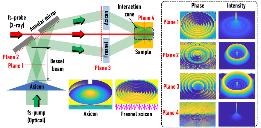
The optical configuration for studying light-matter interactions with co-propagating fs-pump (optical) and fs-probe (X-ray) is studied using a solid axicon as OE1 and a Fresnel axicon with a central hole (Fig. 3) as OE2 is shown in Fig. .1. Collimated light with uniform illumination is incident on a solid axicon with base angle and refractive index . The phase of the solid axicon is given as , where is the radial coordinate. The complex amplitude at a distance can be expressed as a convolution of the complex amplitude from the axicon ) with the quadratic phase function corresponding to that distance . The intensity at any plane is , where ’’ is a 2D convolutional operator. Four planes are considered for the calculation of the complex amplitude. The first plane is selected to be within the focal depth of the axicon. The simulated phase profile shows a conical phase and the intensity has a Bessel-like profile as shown in Fig. .1. The planes 2 and 3 are selected beyond the focal depth of the axicon with the plane 2 matching with the annular mirror plane and the plane 3 matching with the location of the Fresnel axicon[18, 12]. The variation of intensity profile between the two planes shows the evolution of the ring pattern which is the characteristic of an axicon[13] as the conical phase expands. The angle introduced by the annular mirror is avoided in the simulation. The ring pattern encounters the Fresnel axicon whose complex amplitude is given as . Therefore, the complex amplitude immediately after plane 3 is given as . The expression can be rewritten as . The two axicon phases generate a conical phase with a larger base angle and the complex amplitude at a plane closer to the interaction plane resembles a compressed Bessel-like beam with a shorter focal depth and sharper peak.
The advantages and disadvantages of employing a solid axicon as OE1 are as follows. The solid axicon is an optical element with a simpler shape function which is easier for fabrication and less expensive. The complex amplitude generated by the solid axicon-Fresnel axicon pair near the interaction zone is ideal. The use of solid axicon concentrates light in a ring in plane 3 where the Fresnel axicon is located and so the fabrication area of the Fresnel axicon can be much smaller, reducing the cost and fabrication time. However, there are few drawbacks. The intensity distribution has a peak at the center which will not be modulated by the Fresnel axicon as it overlaps with the central hole and will not contribute to the Bessel beam formation. Secondly, the thickness of the ring pattern is larger at plane 2 which demands a larger annular mirror.
Appendix 2 - Simulation of Optical Configuration of Fig. 7 with a conical or toric lens as OE1 and Fresnel axicon as OE2
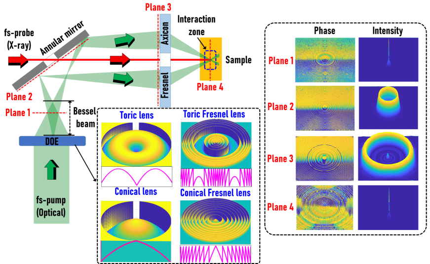
Conical and toric lenses can focus a uniform illumination to a ring and are used for various applications [81, 82, 83]. Since the ring pattern obtained from a toric lens or a conical lens is focused unlike an axicon, a smaller annular mirror could be used. The use of a conical or toric lens also suppresses the central diffraction order. The optical configuration of Fig. 7 with a conical or toric lens is shown in Fig. .2. The presence of an additional quadratic phase in this case compresses the area of the spread of Bessel beam resulting in a reduced interaction area near the sample but with a higher concentration of light energy. Both toric and conical lens has a relatively smoother shape function and therefore can be easily fabricated.
Appendix 3 - Simulation of Optical Configuration of Fig. 7 with a special optical element as OE1 and Fresnel axicon as OE2
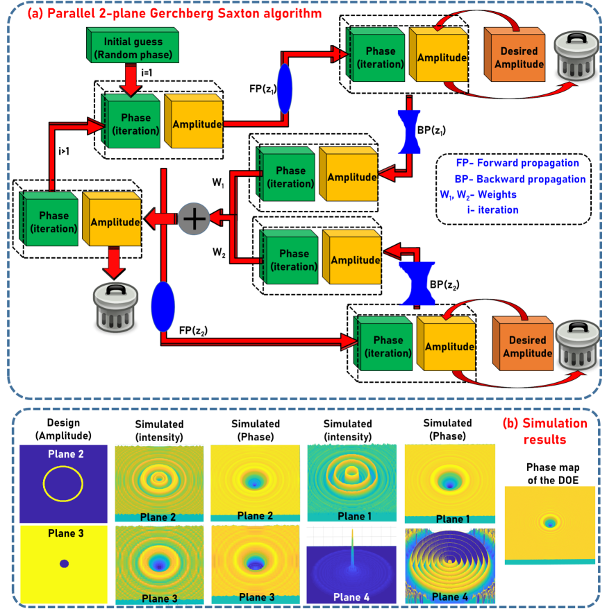
In this case, an element is designed using the Gerchberg-Saxton algorithm (GSA). In the optical configuration, there are two planes of interest, namely plane 2 and plane 3. The original GSA was developed for synthesizing a pure phase function to generate a desired intensity distribution in a particular axial plane, usually the Fourier plane [84]. A modified GSA was developed using Fresnel propagators to synthesize phase patterns that can generate desired intensity distributions in more than one plane in parallel [85, 86, 87]. In this study, the GSA multiple plane approach was implemented to generate desired intensity profiles at plane 2 and plane 3. The flow chart of the two plane GSA is shown in Fig. .3(a). The phase retrieval process for two planes is summarized here. The algorithm begins with an initial random guess of the phase profile. The initial complex amplitude is forward propagated using scalar diffraction formula to two different axial planes and the magnitudes of the complex amplitudes are replaced by the desired ones. The modified complex amplitudes are back propagated to the respective planes and summed. The phase of the resulting complex amplitude is extracted for the next iteration and so on until a minimum error value is obtained between the desired and the obtained intensity distributions. There are weighting factors and attached to the two complex amplitudes before they are added. In this way, it is possible to select a plane where the intensity distribution is more critical than the other and give additional weight. The two intensity profiles designed for this study are a sharp ring pattern at plane 2 and a constant intensity with a central zero intensity at plane 3 [88]. The intensity and phase of the complex amplitudes at different planes are shown in Fig. .3(b). Unlike the previous cases, the central diffraction peak is close to zero in this case. In addition, the phase profile is symmetric and the phase variation is less than which makes the fabrication easier. The complex amplitude near the interaction zone has a larger axial interaction length and Bessel-like intensity profile. In comparison to the above two methods, the results obtained from the two plane GSA is better and does not suffer from fabrication challenges arising from random profiles as in usual cases of GSA.
Appendix 4 - Simulation of Optical Configuration of Fig. 7 with a special optical element as OE1 and spiral axicon as OE2
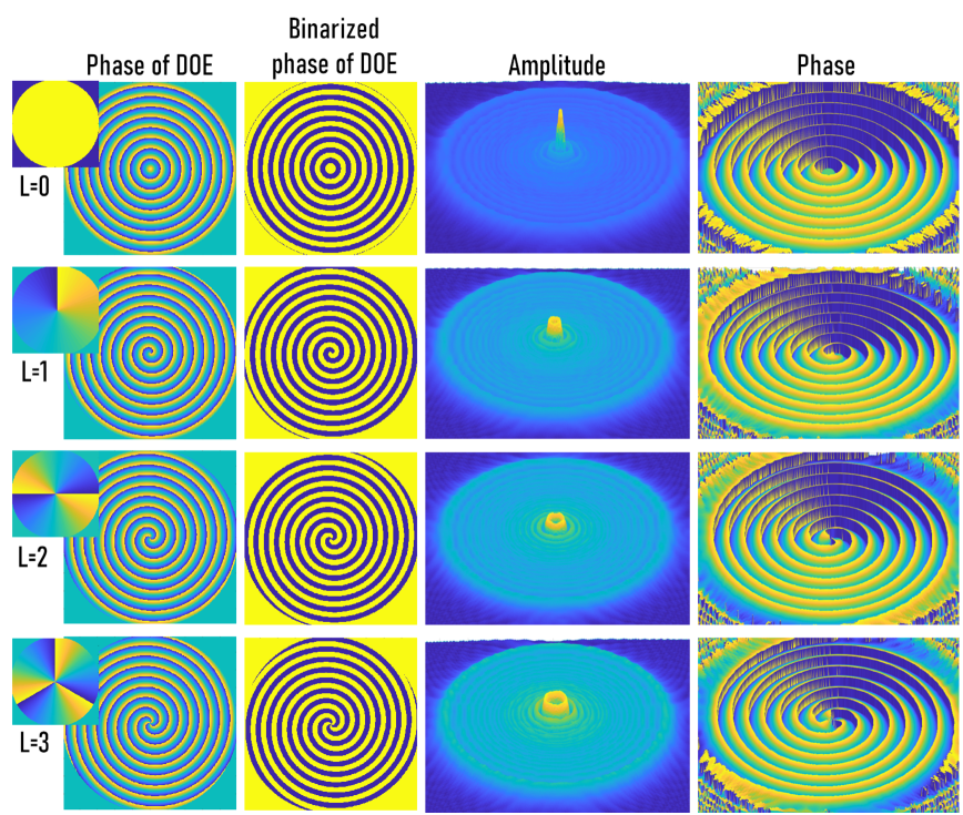
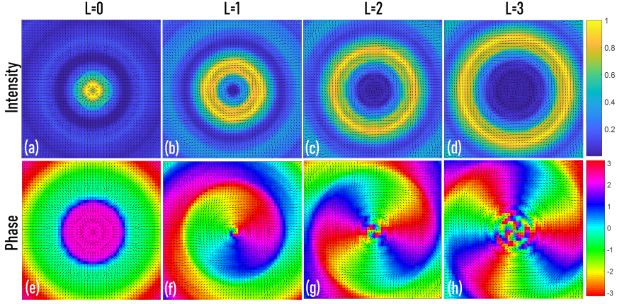
In this case, the special optical element synthesized from the two plane GSA is retained while the Fresnel axicon is replaced by a spiral axicon for OE2. The complex amplitude of the spiral axicon is given as , where is the topological charge and is the azimuthal angle. The spiral axicon is capable of generating higher order Bessel beams (HOBB) with a large focal depth and carries orbital angular momentum [89, 90, 91, 92]. The images of the modulo-2 phase of the spiral axicon for =0, 1, 2 and 3 are shown in Fig. .4. The binary version [0,] is shown which can be fabricated similar to the results shown in Fig. 3. The complex amplitude at plane 4 can be estimated as . The expression can be rearranged as . It is well-established that a convolution between the complex amplitudes of an axicon and a quadratic phase function results in a Bessel-like complex amplitude. This is described in the main text as well. Therefore, the rearrangement of the complex amplitudes with convolution and product shows that the Bessel-like complex amplitude is multiplied by the complex amplitude of the spiral phase function. Consequently, the introduction of the spiral phase creates phase singularities in the Bessel like complex amplitudes resulting in the formation of HOBB. It is seen in Fig. .4 that the radius of the doughnut increases with the topological charge. The amplitude and phase for =0, 1, 2 and 3 are shown in Fig. .4.
Poynting vector plot is a direct method to understanding the directional energy flux or the flow of field. Since all the fields that are studied here are scalar fields, the Poynting vector can be calculated as the product of the intensity and the gradient of the phase [93, 94]. The Poynting vector is given as . The Poynting vector plot is calculated for four cases namely = 0 (Fresnel axicon), 1, 2 and 3 (Spiral axicon) at a plane within the interaction zone. The Poynting vector plots superposed on the respective intensity and phase distributions for the four cases are shown in Fig. .5. From the figure, it is seen that in the case of Fresnel axicon (=0), the Bessel beam can still exert radiation pressure forces due to the intensity gradients [95]. For other cases, as , it is seen that the flux spirals around the center indicating the presence of the orbital angular momentum which can exert forces. When increases, the force field also increases. It is also possible to generate hybrid force fields with both forces from radiation pressure and also orbital angular momentum by spatial multiplexing and by manipulating the phase values.
Summary on possible realisation of optical fs-pump
In this perspective study, we attempted to realize the optical configuration of Fig. 7 using basic optical phase functions such as conical phase, spiral phase, quadratic phase, toric phase and retrieved phase using GSA. These fundamental theoretical and numerical studies reveal the feasibility of the explosion and implosion studies in light-matter interactions with basic optical elements and optical engineering. However, experimental studies are needed to understand the impact of the force fields in the proposed optical configurations. The recent developments on the generation of exotic optical fields such as fields varying in amplitude, phase and polarization [96, 97], vector fields [97], fields generated by OAM superposition [98, 99, 92], OAM beams in unconventional beam channels [100] will enable sophisticated light-matter interactions studies.