A First Principle Study on Magneto-Optical Effects in Ferromagnetic Semiconductors Y3Fe5O12 and Bi3Fe5O12
Abstract
The magneto-optical (MO) effects not only are a powerful probe of magnetism and electronic structure of magnetic solids but also have valuable applications in high-density data-storage technology. Yttrium iron garnet (Y3Fe5O12) (YIG) and bismuth iron garnet (Bi3Fe5O12) (BIG) are two widely used magnetic semiconductors with significant magneto-optical effects. In particular, YIG has been routinely used as a spin current injector. In this paper, we present a thorough theoretical investigation on magnetism, electronic, optical and MO properties of YIG and BIG, based on the density functional theory with the generalized gradient approximation plus onsite Coulomb repulsion. We find that YIG exhibits significant MO Kerr and Faraday effects in UV frequency range that are comparable to ferromagnetic iron. Strikingly, BIG shows gigantic MO effects in visible frequency region that are several times larger than YIG. We find that these distinctly different MO properties of YIG and BIG result from the fact that the magnitude of the calculated MO conductivity () of BIG is one order of magnitude larger than that of YIG. Interestingly, the calculated band structures reveal that both valence and conduction bands across the semiconducting band gap in BIG are purely spin-down states, i.e., BIG is a single spin semiconductor. They also show that in YIG, Y orbitals mix mainly with the high lying conduction bands, leaving Fe orbital dominated lower conduction bands almost unaffected by the SOC on the Y atom. In contrast, Bi orbitals in BIG hybridize significantly with Fe orbitals in the lower conduction bands, leading to large SOC-induced band splitting in the bands. Consequently, the MO transitions between the upper valence bands and lower conduction bands are greatly enhanced when Y is replaced by heavier Bi. This finding suggests a guideline in search for materials with desired MO effects. Our calculated Kerr and Faraday rotation angles of YIG agree well with the available experimental values. Our calculated Faraday rotation angles for BIG are in nearly perfect agreement with the measured ones. Thus, we hope that our predicted giant MO Kerr effect in BIG will stimulate further MOKE experiments on high quality BIG crystals. Our interesting findings show that the iron garnets not only offer an useful platform for exploring the interplay of microwave, spin current, magnetism, and optics degrees of freedom, but also have promising applications in high density MO data-storage and low-power consumption spintronic nanodevices.
I Introduction
Yttrium iron garnet (Y3Fe5O12, YIG) is a ferrimagnetic semiconductor with excellent magnetic properties such as high curie temperature cherepanov1993 , low Gilbert damping kajiwara2010 ; mizukami2002 ; chikazumi1997 and long spin wave propragating length schneider2008 . Various applications such as spin pumping require a non-metallic magnet. YIG is thus routinely used for spin pumping purposes kajiwara2010 . It is also widely used as a magnetic insulating substrate for purposes such as introducing magnetic proximity effect while avoiding electrical short-cut. sun2013 YIG has high Curie temperature, which is good for applications across a wide temperature range. The low Gilbert damping of YIG also makes it a good microwave material. YIG thus becomes a famous material in the field of spintronics, where coupling between magnetism, microwave and spin current becomes possible.
Magneto-optical (MO) effects are important examples of light-matter interactions in magnetic phases. oppeneer2001 ; antonov2004 When a linearly polarized light beam is shined onto a magnetic material, the reflected and transmitted light becomes elliptically polarized. The principal axis is rotated with respect to the polarization direction of incident light beam. The former and latter effects are termed MO Kerr (MOKE) and MO Faraday (MOFE) effects, respectively. MOKE allowes us to detect the magnetization locally with a high spatial and temporal resolution in a non-invasive fashion. Furthermore, magnetic materials with large MOKE would find valuable MO storage and sensor applications mansuripur1995 ; castera1996 . Thus it has been widely used to probe the electronic and magnetic properties of solids, surface, thin films and 2D magnets antonov2004 . On the other hand, MOFE can be used as a time-reversal symmetry-breaking element in optics haldane2008 , and its applications such as optical isolators are consequenses of time-reversal symmetry-breaking aplet1964 . Magnetic materials with large Kerr or Faraday rotation angles have technological applications.
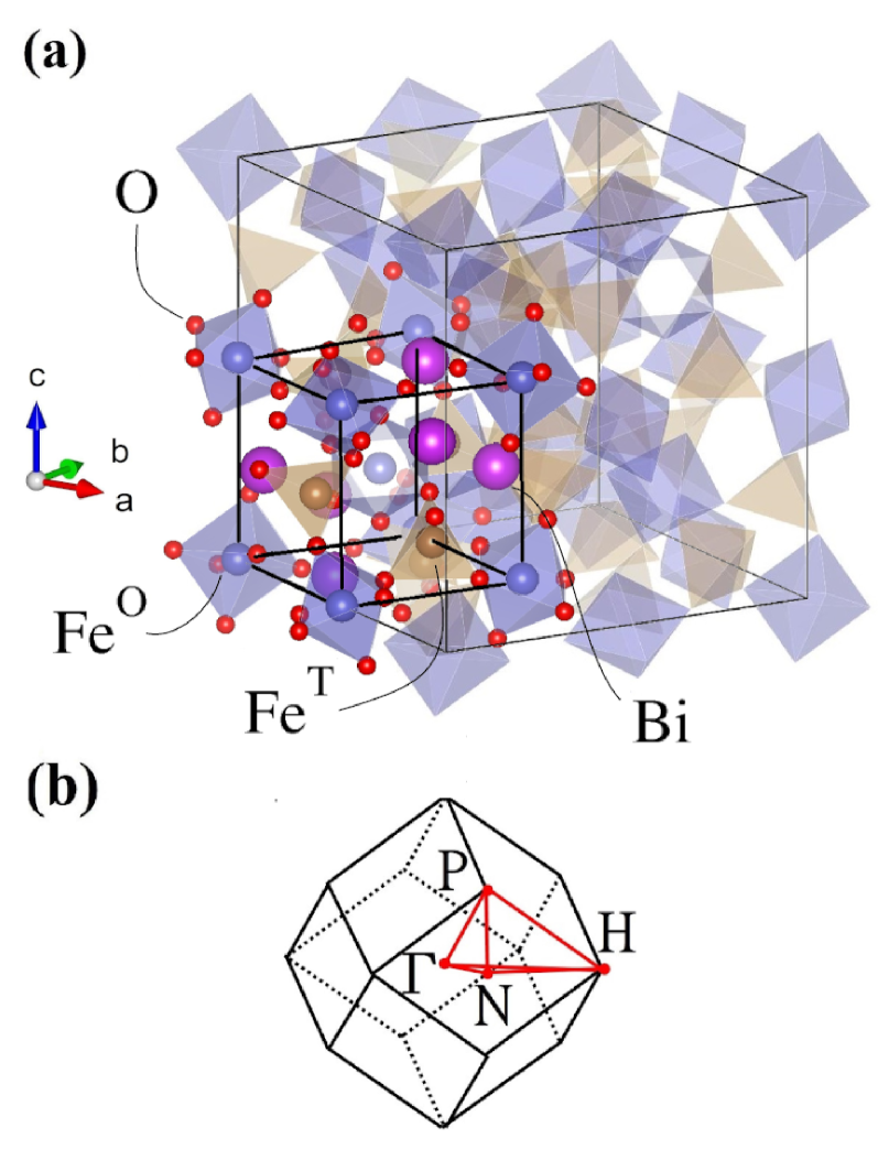
YIG is also known to be MO active dillon1958 . Various experiments have been carried out to study the MOKE and MOFE of iron garnets in the visible and near-UV regime wittekoek1975 ; kahn1969 . Substituting yttrium with bismuth results in bismuth iron garnet (Bi3Fe5O12) (BIG). BIG has approximately 7 times larger Faraday rotation angles than that of YIG. The effect of doping bismuth into YIG on the MOFE spectrum was studied chern1999 ; jesenska2016 . The large radius of bismuth atoms seems to make bulk BIG unstable. Thus high quality BIG film is difficult to synthesize vertruyen2008 . Though numerous experimental studies have been done on these systems, first-principle calculations are scarce. This is probably due to the complexity of the structures of BIG and YIG. As shown in Fig. 1(a), they have a total of 80 atoms in the primitive cell. Although the electronic structures of YIG and BIG have been theoretically studied xu2000 ; oikawa2005 , no first principle calculation on the MOKE or MOFE spectra of YIG and BIG have been reported. Therefore, here we carry out a systematic first-principle density functional study on the optical and MO properties of YIG and BIG. The rest of this paper is organized as follows. A brief description of the crystal structures of YIG and BIG as well as the theoretical methods used is given in Sec. II. In Sec. III, the calculated magnetic moments, electronic structure, optical conductivities, MO Kerr and Faraday effects are presented. Finally, the conclusions drawn from this work are given in section IV.
II CRYSTAL STRUCTURE AND COMPUTATIONAL METHODS
YIG and BIG crystalize in the cubic structure with space group bertaut1956 ; toraya1995 , as illustrated in Fig. 1(a). In each unit cell, there are 48 oxygen atoms at the Wyckoff 96h positions, 8 octahedrally coordinated iron atoms (FeO) at the 16a positions, and 12 tetrahedrally coordinated iron atoms (FeT) at the 24d positions in the primitive cell. In other words, there are two FeO ions and three FeT ions per formula unit (f.u.). The experimental lattice constant Å, and the experimental Wyckoff parameters for oxygen atoms are . bertaut1956 The experimental lattice constant for BIG Å. toraya1995 Accurate oxygen position measurement for BIG is still on demand and under debate vertruyen2008 . Therefore we use the experimental lattice constant for BIG with the atomic positions determined theoretically (see Table I), as described next. We use the experimental lattice constant and atomic positions for all YIG calculations,
| Y3Fe5O12 | Wyckoff position | |||
|---|---|---|---|---|
| FeO | 16a | 0.0000 | 0.0000 | 0.0000 |
| FeT | 24d | 0.3750 | 0.0000 | 0.2500 |
| Y | 24c | 0.1250 | 0.0000 | 0.2500 |
| O | 96h | 0.972611footnotemark: 1 | 0.057211footnotemark: 1 | 0.149211footnotemark: 1 |
| Bi3Fe5O12 | Wyckoff position | |||
| FeO | 16a | 0.0000 | 0.0000 | 0.0000 |
| FeT | 24d | 0.3750 | 0.0000 | 0.2500 |
| Bi | 24c | 0.1250 | 0.0000 | 0.2500 |
| O | 96h | 0.0540 | 0.0300 | 0.1485 |
Ref. bertaut1956, .
Our first principle calculations are based on the density functional theory with the generalized gradient approximation (GGA) of the Perdew-Burke-Ernzerhof formula perdew1996 to the electron exchange-correlation potential. Furthermore, we use the GGA + method to have a better description for on-site interaction for Fe electrons. dudarev1998 Here we set eV, which was found to be rather appropriate for iron oxides jeng2004 . Indeed, as we will show below, the optical and MO spectra calculated using this value agree rather well with the available experimental spectra. All the calculations are carried out by using the accurate projector-augmented wave kresse1999 method, as implemented in Vienna ab initio Simulation Package (VASP). kresse1996a ; kresse1996b A large energy cutoff of 450 eV for the plane-wave basis is used. A -point mesh is used for both systems in the self-consistent charge density calculations. The density of states (DOS) calculation is performed with a denser -point mesh of .
We first calculate the optical conductivity tensor which determine the MOKE and MOFE. We let the magnetization of our systems be along (001) () direction. In this case, our systems have the four-fold rotational symmetry along the axis and thus the optical conductivity tensor can be written in the following form feng2015 :
| (1) |
The optical conductivity tensor can be formulated within the linear response theory. Here the real part of the diagonal elements and imaginary part of the off-diagonal elements are given by wang1974 ; oppeneer1992 ; feng2015 :
| (2) |
| (3) |
where is the photon energy, and are the energy eigenvalues of occupied (unoccupied) states. The transition matrix elements where are the ()th occupied(unoccupied) states at -point k, and is the Cartesian component of the momentum operator. The imaginary part of the diagonal elements and the real part of the off-diagonal elements are then obtained from and , respectively, via the Kramers-Kronig transformations as follows:
| (4) |
| (5) |
where denotes the principal value of the integration. We can see that Eq. (2) and Eq. (3) neglect transitions across different -points since the momentum of the optical photon is negligibly small compared with the electron crystal momentum and thus only the direct interband transitions need to be considered. In our calculations are obtained in the PAW formalism adolph2001 . We use a -point mesh and the Brillouin zone integration is carried out with the linear tetrahedron method (see temmerman1989 and references therein), which leads to well converged results. To ensure that the and in the optical frequency range (e.g., eV) obtained via Eqs. (4) and (5) are converged, we include the unoccupied states at least 21 eV above the Fermi energy, i.e., a total of 1200 (1300) bands are used in the YIG (BIG) calculations.
For a bulk magnetic material, the complex polar Kerr rotation angle is given by guo1994 ; guo1995 ,
| (6) |
Similarly, the complex Faraday rotation angle for a thin film can be written as ravindran1999
| (7) |
where and represent the refractive indices for left- and right-handed polarized lights, respectively, and are related to the corresponding dielectric function (or optical conductivity via expressions . Here the real parts of the optical conductivity can be written as
| (8) |
where . Clearly, , and this shows that would be nonzero only if and are different. In other words, magnetic circular dichroism is the fundamental cause of the nonzero and hence the MO effects.
III RESULTS AND DISCUSSION
III.1 Magnetic moments
| structure | () | () | () | () | ||
|---|---|---|---|---|---|---|
| (/f.u.) | (/atom) | (/atom) | (/atom) | (/atom) | (eV) | |
| Y3Fe5O12 | 4.999 (5.011footnotemark: 1) | -4.177 (-0.016) | 4.075 (0.018) | 0.067 | 0.005 | 1.81 (2.422footnotemark: 2) |
| Bi3Fe5O12 | 4.996 (4.433footnotemark: 3) | -4.161 (-0.018) | 4.068 (0.019) | 0.066 | 0.005 | 1.82 (2.144footnotemark: 4) |
Ref. rodic1999, . 22footnotemark: 2Ref. wittekoek1975, . 33footnotemark: 3Ref. adachi2002, . 44footnotemark: 4Ref. jesenska2016, .
Here we first present calculated total and atom-decomposed magnetic moments in Table I. As expected, Y3Fe5O12 is a ferrimagnet in which Fe ions of the same type couple ferromagnetically while Fe ions of different types couple antiferromagnetically. Since there are two FeO ions and three FeT ions in a unit cell, Y3Fe5O12 is ferrimagnetic with a total magnetic moment per f.u. being 5.0 (see Table I). The calculated spin magnetic moments of Fe ions of both types are 4.0 , being consistent with the high spin state of Fe+2 () ions in either octahedral or tetrahedral crystal field. We note that the orbital magnetic moments of Fe are parallel to their spin magnetic moments. Nonetheless, the calculated orbital magnetic moments of Fe are small, because of strong crystal field quenching. Interestingly, there is a significant spin magnetic moment on each O ion, and this together with the spin magnetic moment of one net Fe ion per f. u. leads to the total spin magnetic moment per f.u. of 5.0 . The calculated Fe magnetic moments for both symmetry sites agree rather well with the measured ones of . rodic1999 The calculated total magnetization of /f.u. is also in excellent agreement with the experiment. rodic1999
Bi3Fe5O12 is also predicted to be ferrimagnetic, although the calculated magnetic moments of both FeO and FeT ions are slightly smaller than the corresponding ones in Y3Fe5O12 (see Table I). The total magnetization and local magnetic moments of the other ions in BIG are almost identical to that in YIG. However, the experimental for BIG is only , adachi2002 being significantly smaller than the calculated value. As mentioned before, stable high quality BIG crystals are hard to grow. Consequently, this notable discrepancy in total magnetization between the calculation and the previous experiment adachi2002 could be due to the poor quality of the samples used in the experiment.
III.2 Electronic structure
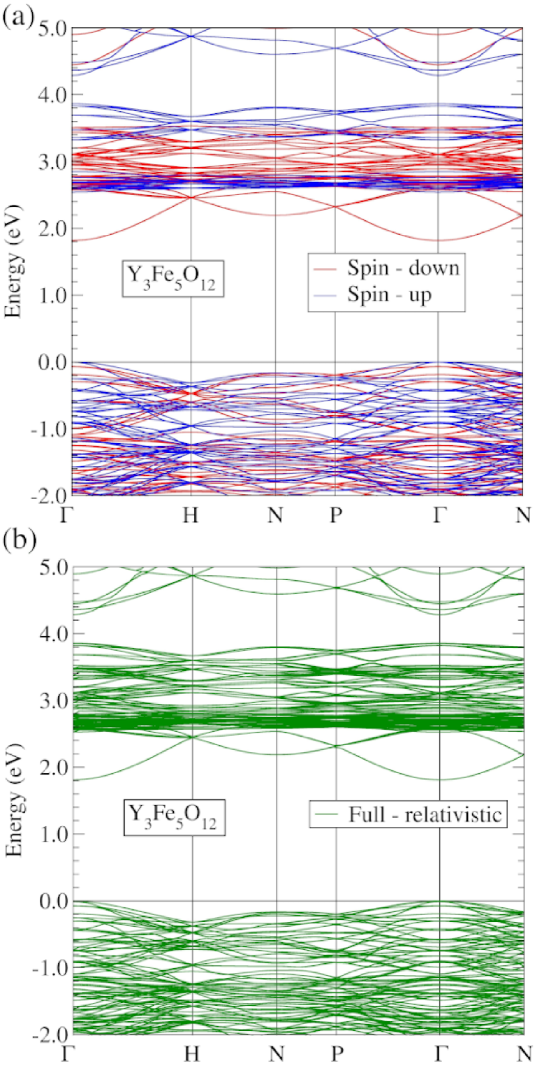
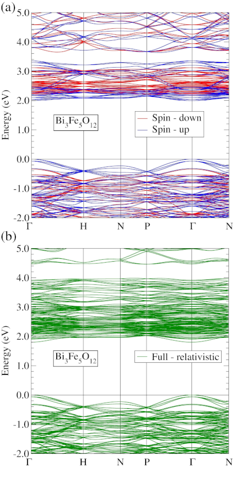
Here we present the calculated scalar-relativistic band structures of YIG and BIG in Fig. 2(a) and Fig. 3(a), respectively. The calculated band structures show that YIG and BIG are both direct band-gap semiconductors, where the conduction band minimum (CBM) and valence band maximum (VBM) are both located at the point. For BIG, both CBM and VBM are purely spin-up bands. This means that BIG is a single-spin semiconductor, which may find applications for spintronic and spin photovoltaic devices. The origin of the MO effects is the magnetic circular dichorism [see Eq. (8)], as mentioned above, which cannot occur without the presence of the spin-orbit coupling (SOC). Therefore, it is useful to examine how the SOC influence the band structures. The fully relativistic band structures for YIG and BIG are presented in Fig. 2(b) and Fig. 3(b), respectively. First, we notice that with the inclusion of the SOC, YIG and BIG are still direct band-gap semiconductors, where the CBM and VBM are both located at the point. Second, Fig. 3(b) indicates that when the SOC is considered, the BIG band structure changes significantly, while the YIG band structure hardly changes [see Fig. 2(b)]. For example, the band gap for BIG decreases from 2.0 to 1.8 eV after the SOC is included. Also, the gap, which was at 3.4 to 3.7 eV above the Fermi energy [see Fig. 3(a)], now becomes from 3.9 to 4.5 eV above the Fermi energy [see Fig. 3(b)]. Interestingly, the substitution of yittrium by bismuth not only enhances the SOC but also changes the electronic band structure significantly, as can be seen by comparing Figs. 2 and 3.
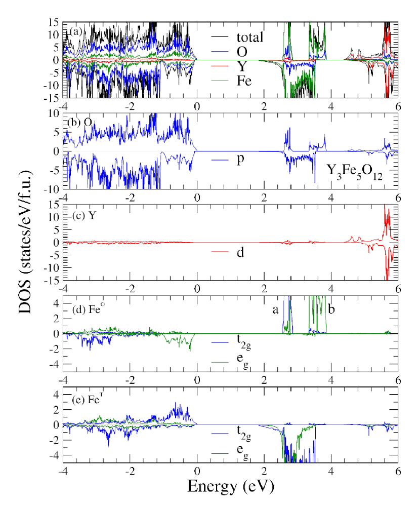
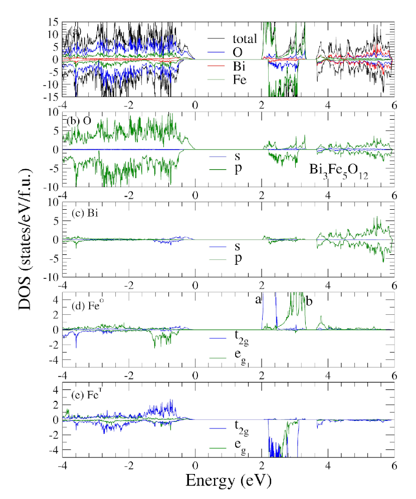
We also calculate total as well as site-, orbital-, and spin-projected densities of states (DOS) for YIG and BIG, as displayed in Fig. (4) and (5), respectively. First, Figs. (4) and (5) show that in both YIG and BIG, the upper valence bands ranging from -4.0 to 0.0 eV, are dominated by O -orbitals with minor contributions from Fe -orbitals as well as Y -orbitals in YIG and Bi -orbitals in BIG. Second, the lower conduction band manifold, ranging from 1.8 to 3.9 eV in YIG (Fig. 4) and from 2.0 to 3.4 eV in BIG (Fig. 5), stems predominately from Fe -orbitals with small contributions from O -orbitals. Therefore, the semiconducting band gaps in YIG and BIG are mainly of the charge transfer type. Furthermore, on the FeT sites, the -DOS in this conduction band is almost fully spin-down [see Figs. 4(e) and 5(e)]. On the FeO sites, on the other hand, the -DOS in this conduction band is almost purely spin-up [see Figs. 4(d) and 5(d)]. Here, the DOS peak marked mostly consists of orbital while that marked above peak , is made up of mainly orbital. The gap between peaks and is thus caused by the crystal field splitting.
Figure 4 indicates that in YIG, the upper conduction bands from 4.4 to 6.0 eV are mainly of Y orbital character with some contribution from O orbitals. In BIG, on the other hand, the upper conduction bands from 3.6 to 6.0 eV are mainly the Bi and O orbital hybridized bands (see Fig. 5). Notably, there is sizable Bi DOS in the lower conduction band region from 2.0 to 3.4 eV (see Fig. 5(c)], indicating that the lower conduction bands in BIG are significantly mixed with Bi orbitals, as noticed already by Oikawa et al. oikawa2005 , Since the SOC of the Bi orbitals are very strong, this explains why the band width of the lower conduction bands in BIG increases from 1.4 to 2.1 eV when the SOC is included (see Fig. 3). In contrast, the band width of the lower conduction bands in YIG remains unaffected by the SOC (see Fig. 2). This also explains why the MO effects in BIG are much stronger than in YIG, as reported in Sec. III.D. below.
III.3 Optical Conductivity
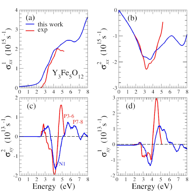
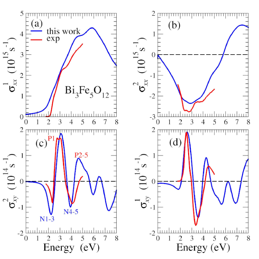
Here we present the optical and magneto-optical conductivities for YIG and BIG which are ingredients for calculating the Kerr and Faraday rotation angles [see Eq. (6) and Eq. (7)]. In particular, the MO conductivity (i.e., the off-diagonal element of the conductivity tensor ) is crucial, as shown by Eq. (8). Calculated optical conductivity spectra of YIG and BIG are plotted as a function of photon energy in Fig. 6 and Fig. 7, respectively. For YIG, the real part of the diagonal element of the conductivity tensor () starts to increase rapidly from the absorption edge ( 2.3 eV) to 4.0 eV, and then further increases with a smaller slope up to 5.6 eV [see Fig. 6(a)]. It then decreases slightly until 6.6 eV and finally increases again with a much steeper slope up to 8.0 eV. Similarly, in BIG, increases steeply from the absorption edge ( 2.0 eV) to 4.0 eV, and then further increases with a smaller slope up to 6.0 eV [see Fig. 7(a)]. It then decrease steadily from 6.0 eV to 8.0 eV. The behaviors of the imaginary part of the diagonal element () of YIG and BIG are rather similar in the energy range up to 5.0 eV [see Figs. 6(b) and 7(b)]. The spectrum has a broad valley at 3.5 eV ( 3.0 eV) in the case of YIG (BIG). However, the spectra of YIG and BIG differ from each other for energy 5.0 eV. There is a sign change in occuring at 5.8 eV for BIG, while there is no such a sign change in of YIG up to 8.0 eV.
The striking difference in the off-diagonal element of the conductivity () (i.e., magneto-optical conductivity or magnetic circular dichroism) between YIG and BIG is that of BIG is almost ten times larger than that of YIG (see Figs. 6 and 7). Nonetheless, the line shapes of the off-diagonal element of YIG and BIG are rather similar except that their signs seem to be opposite and their peaks appear at quite different energy positions. In particular, in the low energy range up to 4.4 eV, the line shape of the imaginary part of the off-diagonal element () of BIG looks like a ”W” [see Fig. 7(c)], while that of YIG in the energy region up to 7.0 eV seems to have the inverted ”W” shape [see Fig. 6(c)], The main difference is that the of BIG decreases oscillatorily from 4.4 to 8.0 eV. On the other hand, the line shape of the real part of the off-diagonal element () of BIG looks like a ”sine wave” between 2.0 and 4.7 eV [see Fig. 7(d)], while that of YIG appears to be an inverted ”sine wave” between 2.6 and 6.4 eV [see Fig. 6(d)]. The largest magnitude of of YIG is at 4.3 eV, while that of BIG is at 3.1 eV. The largest magnitude of of YIG is at 4.8 eV, while that of BIG is at 2.6 eV.
In order to compare with the available experimental data, we also plot the experimental optical conductivity spectra wittekoek1975 ; jesenska2016 in Figs. 6 and 7. The theoretical spectra of the diagonal element of the optical conductivity tensor for both YIG and BIG match well with that of the experimental ones in the measured energy range [see Figs. 6(a) and 6(b) as well as Figs. 7(a) and 7(b)]. Interestingly, we note that the relativistic GGA+U calculations give rise to the band gaps of YIG and BIG that are smaller than the experimental ones (see Table II), and yet the calculated and measured optical spectra agree rather well with each other. This apparently contradiction can be resolved as follows. In YIG, for example, the lowest conduction bands at eV above the VBM are highly dispersive (see Fig. 2) and thus have very low DOS (see Fig. 4). This results in very low optical transition. Therefore, the main absoption edge that appears in the optical spectrum () is eV, which is close to the experimental absorption edge of 2.5 eV, instead of 1.8 eV as determined by the calculated band structure (see Table II). In contrast, no such highly dispersive bands appear at the CBM in BIG, Thus the calculated band gap agrees better with the measured band gap jesenska2016 (Table II).
Figures 7(c) and 7(d) show that the calculated and of BIG agree almost perfectly with the experimental data jesenska2016 . The peak positions, peak heights and overall trend of the theoretical spectra are nearly identical to that of the experimental ones jesenska2016 . On the other hand, the calculated and for YIG do not agree so well with the experimental data wittekoek1975 [Figs. 6(c) and 6(d]. For example, there is a sharp peak at 4.8 eV in the experimental spectrum, which seems to be shifted to a higher energy at 5.6 eV with much reduced magnitude in the theoretical spectrum [see Fig. 6(c)]. Also, for spectrum, there is a sharp peak at 4.5 eV in the experimental spectrum, which appears at eV with considerably reduced height [see Fig. 6(d)]. Nonetheless, the overall trend of the theoretical spectra of YIG is in rather good agreement with that of the measured ones wittekoek1975 .
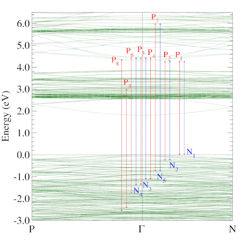
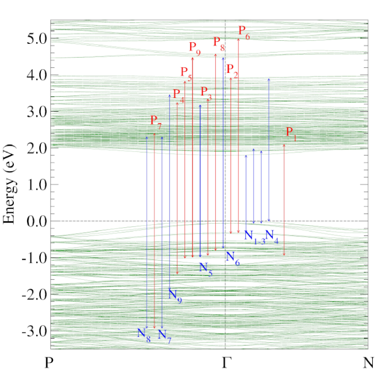
Equations (2), (3), and (8) indicate that the absorptive parts of the optical conductivity elements ( and ) are directly related to the dipole allowed interband transitions. Thus, we analyze the origin of the main features in the magneto-optical conductivity () spectrum by determining the symmetries of the involved band states and the dipole selection rules (see the Appendix for details). The absorptive optical spectra are usually dominated by the interband transitions at the high symmetry points where the energy bands are generally flat (see, e.g., Figs. 2 and 3), thus resulting in large joint density of states. As an example, here we consider the interband optical transitions at the point where the band extrema often occur. Based on the determined band state symmetries and dipole selection rules (see Table III in the Appendix) as well as calculated transition matrix elements [Im], we assign the main features in [labelled in Figs. 6(c) and 7(c)] to the main interband transitions at the point as shown in Figs. 8 and 9. The details of these assignments, related interband transitions and transition matrix elements for YIG and BIG are presented in Tables IV and V in the Appendix, respectively. Since there are too many possible transitions to list, we present only those transitions whose transition matrix elements Im a.u. in YIG (Table IV) and Im a.u. in BIG (Table V).
Figure 8 shows that nearly all the main optical transitions in YIG are from the upper valence bands to the upper conduction bands, and only one main transition (P3) to the lower conduction bands. Consequently, these transitions contribute to the main features in at photon energy eV [see Fig. 6(c)]. In contrast, in BIG, a large number of the main transitions (e.g., P1-5, P7, N1-4, N5-8) are from the upper valence bands to lower conduction bands (see Fig. 9). This gives rise to the main features in for photon energy eV [see Fig. 7(c)], whose magnitudes are generally one order of magnitude larger than that of in YIG, as mentioned above. The largely enhanced MO activity in BIG stems from the significant hybridization of Bi -orbitals with Fe -orbitals in the lower conduction bands, as mentioned above. Since heavy Bi has a strong spin-orbit coupling, this hybridization greatly increases the dichroic interband transitions from the upper valence bands to the lower conduction bands in BIG. As mentioned above, Y orbitals contribute significantly only to the upper conduction bands in YIG, and this results in the pronounced magneto-optical transitions only from the upper valence bands to the upper conduction bands (Fig. 8). Furthermore, Y is lighter than Bi and thus has a weaker SOC than Bi.
The discussion in the proceeding paragraph clearly indicates that the significant hybridization of heavy Bi orbitals with Fe orbitals in the lower conduction bands just above the band gap is the main reason for the large MO effect in BIG. The magnetism in BIG is mainly caused by the iron orbitals which have a rather weak SOC. However, through the hybridization between Bi orbitals and Fe orbitals, the strong SOC effect is also transfered to the lower conduction bands. Large exchange splitting and strong spin-orbit coupling in the valence and conduction bands below and above the band gap are crucial for strong magnetic circular dichroism and hence large MO effects. Therefore, in search of materials with strong MO effects, one should look for magnetic systems that contain heavy elements such as Bi and Pt guo1996 .
III.4 Magneto-optical Kerr and Faraday effect
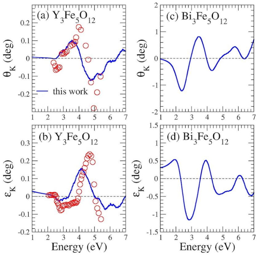
Finally, let us study the polar Kerr and Faraday effects in YIG and BIG. The complex Kerr and Faraday rotation angles for YIG and BIG are plotted as a function of photon energy in Figs. 8 and 9, respectively. First of all, we notice that the Kerr rotation angles of BIG [Fig. 10(c)] are many times larger than that of YIG [Fig. 10(a)]. For example, the positive Kerr rotation maximum of 0.10 ∘ in YIG occurs at eV, while that (0.80 ∘) for BIG appears at eV. The negative Kerr rotation maximum (-0.12 ∘) of YIG occurs at eV, while that (-1.21 ∘) for BIG appears at eV. This may be expected because Kerr rotation angle is proportional to the MO conductivity () [Eq. (6)], which in BIG is nearly ten times larger than in YIG, as mentioned in the proceeding subsection. Similarly, the Kerr ellipticity maximum (0.16 ∘) of YIG occurs at eV [Fig. 10(b)], whereas that (0.54 ∘) of BIG [Fig. 10(d)] appears at eV. The negative Kerr ellipticity maximum (-0.07 ∘) of YIG occurs at eV while that (-1.16∘) of BIG is located at eV.
Let us now compare our calculated Kerr rotation angles with some known MO materials such as transition metal alloys and compound semiconductors. antonov2004 For magnetic metals, ferromagnetic transition metals and their alloys are an important family. Among them, manganese-based pnictides are known to have strong MO effects. In particular, MnBi thin films were reported to have a large Kerr rotation angle of 2.3 ∘. di1996 ; ravindran1999 Platinum alloys such as FePt, Co2Pt guo1996 and PtMnSb vanengen1983 also possess large Kerr rotation angles. It was shown that the strong SOC on heavy Pt in these systems is the main cause of the strong MOKE. guo1996 Among semiconductor MO materials, diluted magnetic semiconductors Ga1-xMnxAs were reported to show Kerr rotations angle as large as 0.4 ∘at 1.80 eV. lang2005 Therefore, the strong MOKE effect in YIG and BIG could have promising applications in high density MO data-storage devices or MO nanosensors with high spatial resolution.
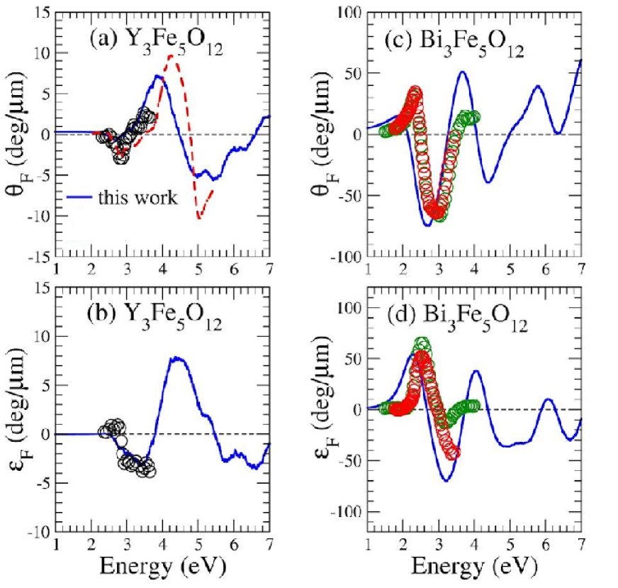
Figure 9 shows that as for the Kerr rotation angles, the Faraday rotation angles of BIG are generally up to ten times larger than that of YIG. The Faraday rotation maximum (7.2 ∘/m) of YIG occurs at eV, while that (51.2∘/m) of BIG is located at eV. The Faraday ellipticity maximum (7.9 ∘/m) for YIG appears at eV, whereas that (54.1∘/m) of BIG occurs at eV. On the other hand, the negative Faraday rotation maximum (-5.7∘/m) occurs at eV, while that (-74.6∘/m) for BIG appears at eV. The negative Faraday ellipticity maximum (-3.6∘/m) of YIG occurs at eV, while that (-70.2∘/) for BIG is located at eV. For comparision, we notice that MnBi films are known to possess large Faraday rotation angles of ∘/m at 1.8 eV. di1996 ; ravindran1999
Finally, we compare our predicted MOKE and MOFE spectra with the available experiments in Figs. 10 and 11. All the predicted MOKE and MOFE spectra are in rather good agreement with the experimental ones in the experimental photon energy range kahn1969 ; wittekoek1975 ; jesenska2016 ; deb2012 . Nonetheless, our theoretical predictions would have a better agreement with the experiments if all the calculated spectra are blue-shifted slightly by 0.3 eV, thus suggesting that the theoretical band gaps are slightly too small.
IV Conclusion
To summarize, we have systematically studied the electronic structure, magnetic, optical and MO properties of cubic iron garnets YIG and BIG by performing GGA+U calculations. We find that YIG exhibits significant MO Kerr and Faraday effects in UV frequency range that are comparable to cubic ferromagnetic iron. Strikingly, we find that BIG shows gigantic MO effects in the visible frequency region that are several times larger than YIG. In particular, the Kerr rotation angle of BIG becomes as large as -1.2∘at photon energy 2.4 eV, and the Faraday rotation angle for the BIG film reaches -75 ∘/ at 2.7 eV. Calculated MO conductivity () spectra reveal that these distinctly different MO properties of YIG and BIG result from the fact that the magnitude of of BIG is nearly ten times larger than that of YIG. Our calculated Kerr and Faraday rotation angles of YIG agree well with the available experimental values. Our calculated Faraday rotation angles of BIG are in nearly perfect agreement with the measured ones. Thus, we hope that our predicted giant MO Kerr effect in BIG will stimulate further MOKE experiments on high quality BIG crystals.‘
Principal features in the optical and MO spectra are analyzed in terms of the calculated band structures especially the symmetry of the band states and optical transition matrix elements at the point of the BZ. We find that in YIG, Y orbitals mix mainly with the upper conduction bands that are eV above the VBM, and thus leave the Fe orbital dominated lower conduction bands from 1.8 to 3.8 eV above the VBM almost unaffected by the SOC on the Y atom. In contrast, Bi orbitals in BIG hybridize significantly with Fe orbitals in the lower conduction bands and this leads to large SOC-induced band splitting and much increased band width of the lower conduction bands. Consequently, the MO transitions between the upper valence bands and lower conduction bands are greatly enhanced when Y is replaced by heavier Bi. This finding thus provides a guideline in search for materials with desired MO effects, i.e., one should look for magnetic materials with heavy elements such as Bi whose orbitals hybridize significantly with the MO active conduction or valence bands.
Finally, our findings of strong MO effects in these iron garnets and also single-spin semiconductivity in BIG suggest that cubic iron garnets are an useful playground of exploring the interplay of microwave, spin current, magnetism, and optics degrees of freedom, and also have promising applications in high density semiconductor MO data-storage and low-power consumption spintronic nanodevices.
Acknowledgments
The authors thank Ming-Chun Jiang for many valuable discussions throughout this work. The authors acknowledge the support from the Ministry of Science and Technology and the National Center for Theoretical Sciences (NCTS) of The R.O.C. The authors are also grateful to the National Center for High-performance Computing (NCHC) for the computing time. G.-Y. Guo also thanks the support from the Far Eastern Y. Z. Hsu Science and Technology Memorial Foundation in Taiwan.
APPENDIX: Dipole selection rules and symmetries of band states at
In this Appendix, to help identify the origins of the main features in the magneto-optical conductivity spectra of YIG and BIG, we provide the dipole selection rules and the symmetries of the band states at the as well as the main optical transitions between them.
Both YIG and BIG have the Iad space group and thus they have the () point group at the point in the Brillouin zone. Based on the character table of the point group koster1963 , we determine the dipole selection rules for the optical transitions between the band states at the point, as listed in Table III. We calculate the eigenvalues for all symmetry elements of each eigenstate of the point using the Irvsp program gao2020 and then determine the irreducible representation and hence the symmetry of the state. Based on the obtained symmetries of the band states and also calculated optical matrix elements [Im] [see Eq. (3)], we assign the peaks in the spectra of YIG [see Fig. 6(c)] and BIG [see Fig. 7(c)] to the main optical transitions at the point (see Fig. 8 and 9, respectively), as listed in Tables IV and V, respectively.
| polarization | |||||||||
|---|---|---|---|---|---|---|---|---|---|
| Peak | state | state | Im | |||
|---|---|---|---|---|---|---|
| P8 | 545 () | 802 () | 0.0103 | 6.928 | 4.358 | -2.569 |
| P3 | 556 () | 761 () | 0.0115 | 5.438 | 3.010 | -2.428 |
| P6 | 609 () | 803 () | 0.0102 | 6.207 | 4.442 | -1.765 |
| N4 | 632 () | 803 () | -0.0273 | 5.825 | 4.442 | -1.384 |
| P5 | 635 () | 803 () | 0.0251 | 5.818 | 4.442 | -1.376 |
| N3 | 649 () | 803 () | -0.0146 | 5.567 | 4.442 | -1.125 |
| P4 | 651 () | 803 () | 0.0195 | 5.564 | 4.442 | -1.123 |
| P7 | 668 () | 844 () | 0.0136 | 6.744 | 5.994 | -0.750 |
| N5 | 670 () | 844 () | -0.0119 | 6.739 | 5.994 | -0.745 |
| P2 | 690 () | 801 () | 0.0116 | 4.537 | 4.280 | -0.257 |
| N2 | 692 () | 801 () | -0.0107 | 4.535 | 4.280 | -0.254 |
| P1 | 698 () | 801 () | 0.0431 | 4.292 | 4.280 | -0.012 |
| N1 | 700 () | 801 () | -0.0452 | 4.280 | 4.280 | 0.000 |
| Peak | state | state | Im | |||
|---|---|---|---|---|---|---|
| N8 | 578 () | 783 () | -0.0130 | 5.234 | 2.304 | -2.930 |
| P7 | 578 () | 789 () | 0.0123 | 5.331 | 2.401 | -2.930 |
| N7 | 579 () | 782 () | -0.0139 | 5.228 | 2.298 | -2.930 |
| N9 | 661 () | 856 () | -0.0136 | 5.333 | 3.452 | -1.882 |
| P4 | 684 () | 846 () | 0.0127 | 4.685 | 3.242 | -1.443 |
| P5 | 709 () | 869 () | 0.0139 | 4.839 | 3.825 | -1.014 |
| P9 | 710 () | 873 () | 0.0149 | 5.453 | 4.467 | -0.986 |
| N5 | 712 () | 842 () | -0.0121 | 4.153 | 3.175 | -0.979 |
| P3 | 715 () | 854 () | 0.0135 | 4.271 | 3.336 | -0.935 |
| P8 | 723 () | 876 () | 0.0142 | 5.374 | 4.571 | -0.803 |
| N6 | 727 () | 873 () | -0.0145 | 5.206 | 4.467 | -0.738 |
| P2 | 741 () | 872 () | 0.0122 | 4.254 | 3.917 | -0.337 |
| P6 | 743 () | 878 () | 0.0127 | 5.305 | 4.991 | -0.314 |
| N3 | 743 () | 749 () | -0.0184 | 2.113 | 1.799 | -0.314 |
| N2 | 744 () | 755 () | -0.0160 | 2.037 | 1.973 | -0.063 |
| N1 | 745 () | 753 () | -0.0142 | 1.980 | 1.917 | -0.062 |
| N4 | 747 () | 871 () | -0.0138 | 3.891 | 3.891 | 0.000 |
| P1 | 715 () | 760 () | 0.0125 | 3.032 | 2.097 | -0.935 |
References
- (1) V. Cherepanov, I. Kolokolov, and V. L’vov, The saga of YIG: spectra, thermodynamics, interaction and relaxation of magnons in a complex magnet, Phys. Rep. 229, 81 (1993).
- (2) S. Mizukami, Y. Ando, and T. Miyazaki, Effect of spin diffusion on Gilbert damping for a very thin permalloy layer in Cu/permalloy/Cu/Pt films, Phys. Rev. B66, 104413 (2002).
- (3) S. Chikazumi, Physics of Ferromagnetism, 2nd ed. (Oxford University Press, Oxford, 1997)
- (4) Y. Kajiwara, K. Harii, S. Takahashi, J. Ohe, K. Uchida, M. Mizuguchi, H. Umezawa, H. Kawai, K. Ando, K. Takanashi, S. Maekawa, and E. Saitoh, Transmission of electrical signals by spin-wave interconversion in a magnetic insulator, Nature (London) 464, 262 (2010).
- (5) T. Schneider, A. A. Serga, B. Leven, B. Hillebrands, R. L. Stamps, and M. P. Kostylev, Realization of spin-wave logic gates, Appl. Phys. Lett. 92(2), 022505 (2008).
- (6) Y. Sun, H. Chang, M. Kabatek, Y.-Y. Song, Z. Wang, M. Jantz, W. Schneider, M. Wu, E. Montoya, B. Kardasz, B. Heinrich, S. G. E. te Velthuis, H. Schultheiss, and A. Hoffmann, Damping in Yttrium Iron Garnet Nanoscale Films Capped by Platinum, Phys. Rev. Lett. 111, 106601 (2013).
- (7) P. M. Oppeneer, Chapter 1 Magneto-optical Kerr Spectra, pp. 229-422, in Handbook of Magnetic Materials, edited by K. H. J. Buschow. Elsevier, Amsterdam, (2001).
- (8) V. Antonov, B. Harmon, and A. Yaresko. Electronic structure and magneto-optical properties of solids. Springer Science & Business Media, (2004).
- (9) J. P. Castera, in Magneto-optical Devices, Vol. 9 of Encyclopedia of Applied Physics, edited by G. L. Trigg (Wiley-VCH, New York, 1996), p. 133.
- (10) M. Mansuripur, The Principles of Magneto-Optical Recording (Cambridge Univ. Press, Cambridge, 1995).
- (11) F. D. M. Haldane and S. Raghu, Possible Realization of Directional Optical Waveguides in Photonic Crystals with Broken Time-Reversal Symmetry, Phys. Rev. Lett. 100, 013904 (2008).
- (12) L. J. Aplet and J. W. Carson, A Faraday effect optical isolator, Appl. Opt. 3, 544 (1964).
- (13) J. F. Dillon, Optical properties of several ferrimagnetic garnets, J. Appl. Phys. 29, 539 (1958).
- (14) S. Wittekoek, T. J. A. Popma, J. M. Robertson, P. F. Bongers, Magneto-optic spectra and the dielectric tensor elements of bismuth-substituted iron garnets at photon energies between 2.2-5.2 eV, Phys. Rev. B 12, 2777 (1975).
- (15) F. J. Kahn, P. S. Pershan, and J. P. Remeika, Ultraviolet Magneto-Optical Properties of Single-Crystal Orthoferrites, Garnets, and Other Ferric Oxide Compounds, Phys. Rev. 186, 891 (1969).
- (16) M. -Y. Chern, F. -Y. Lo, D. -R. Liu, K. Yang, and J. -S. Liaw, Red shift of Faraday rotation in thin films of completely bismuth-substituted iron garnet Bi3Fe5O12 , Jpn. J. App. Phys., Part 1 38, 6687 (1999).
- (17) E. Jesenska, T. Yoshida, K. Shinozaki, T. Ishibashi, L. Beran, M. Zahradnik, R. Antos, M. Kuera, and M. Veis, Optical and magneto-optical properties of Bi substituted yttrium iron garnets prepared by metal organic decomposition, Opt. Mater. Express 6(6), 1986-1997 (2016).
- (18) B. Vertruyen, R. Cloots, J. S. Abell, T. J. Jackson, R. C. da Silva, E. Popova, and N. Keller, Curie temperature, exchange integrals, and magneto-optical properties in off-stoichiometric bismuth iron garnet epitaxial films, Phys. Rev. B 78, 094429 (2008).
- (19) Y. -N. Xu, Z. -Q. Gu, and W. Y. Ching, First-principles calculation of the electronic structure of yttrium iron garnet (Y3Fe5O12), J. Appl. Phys. 87, 4867 (2000).
- (20) T. Oikawa, S. Suzuki, and K. Nakao, First-principles study of spin-orbit interactions in bismuth iron garnet, J. Phys. Soc. Jpn. 74, 401 (2005).
- (21) F. Bertaut, F. Forrat, A. Herpin, and P. Mériel, Étude par diffraction de neutrons du grenat ferrimagnétique Y3Fe5O12, Compt. rend. 243, 898 (1956).
- (22) H. Toraya and T. Okuda, Crystal structure analysis of polycrystalline Bi3Fe5O12 thin film by using asymmetric and symmetric diffraction techniques, J. Phys. Chem. Solids 56, 1317 (1995).
- (23) J. P. Perdew, K. Burke, and M. Ernzerhof, Generalized Gradient Approximation Made Simple, Phys. Rev. Lett. 77, 3865 (1996).
- (24) S. L. Dudarev, G. A. Botton, S. Y. Savrasov, C. J. Humphreys and A. P. Sutton, Electron-energy-loss spectra and the structural stability of nickel oxide: An LSDA+ U study, Phys. Rev. B 57, 1505 (1998).
- (25) H.-T. Jeng, G. Y. Guo and D. J. Huang, Charge-orbital ordering and Verwey transition in magnetite, Phys. Rev. Lett. 93, 156403 (2004).
- (26) G. Kresse and D. Joubert, From ultrasoft pseudopotentials to the projector augmented-wave method, Phys. Rev. B 59, 1758 (1999).
- (27) G. Kresse and J. Furthmüller, Efficient iterative schemes for ab initio total-energy calculations using a plane-wave basis set, Phys. Rev. B 54, 11169 (1996).
- (28) G. Kresse and J. Furthmüller, Efficiency of ab-initio total energy calculations for metals and semiconductors using a plane-wave basis set, Comput. Mat. Sci 6, 15 (1996).
- (29) W. Feng, G.-Y. Guo, J. Zhou, Y. Yao, and Q. Niu, Large magneto-optical Kerr effect in noncollinear antiferromagnets Mn ( Rh, Ir, Pt) Phys. Rev. B 92, 144426 (2015).
- (30) C. S. Wang and J. Callaway, Band structure of nickel: Spin-orbit coupling, the Fermi surface, and the optical conductivity, Phys. Rev. B 9, 4897 (1974).
- (31) P. M. Oppeneer, T. Maurer, J. Sticht, and J. Kübler, calculated magneto-optical Kerr effect of ferromagnetic metals: Fe and Ni, Phys. Rev. B 45, 10924 (1992).
- (32) B. Adolph, J. Furthmüller, and F. Bechstedt, Optical properties of semiconductors using projector-augmented waves, Phys. Rev. B 63, 125108 (2001).
- (33) W. M. Temmerman, P. A. Sterne, G. Y. Guo, and Z. Szotek, Electronic Structure Calculations of High Tc Materials, Mol. Simul. 63, 153 (1989).
- (34) G.-Y. Guo and H. Ebert, Theoretical investigation of the orientation dependence of the magneto-optical Kerr effect in Co, Phys. Rev. B 50, 10377 (1994).
- (35) G.-Y. Guo and H. Ebert, Band-theoretical investigation of the magneto-optical Kerr effect in Fe and Co multilayers, Phys. Rev. B 51, 12633 (1995).
- (36) D. Rodic, M. Mitric, R. Tellgren, H. Rundlof, and A. Kremenovic, True magnetic structure of the ferrimagnetic garnet Y3Fe5O12 and magnetic moments of iron ions, J. Magn. Magn. Mater. 191, 137 (1999).
- (37) N. Adachi, T. Okuda, V. P. Denysenkov, A. Jalali-Roudsar, and A. M. Grishin, Magnetic properties of single crystal film Bi3Fe5O12 prepared onto Sm3(Sc,Ga)5O12(1 1 1), J. Magn. Magn. Mater. 242-245, 775 (2002).
- (38) G. Y. Guo and H. Ebert, On the origins of the enhanced magneto-optical Kerr effect in ultrathin Fe and Co multilayers, J. Magn. Magn. Mater. 156, 173 (1996).
- (39) P. Ravindran, A. Delin, P. James, B. Johansson, J. Wills, R. Ahuja, and O. Eriksson, Magnetic, optical, and magneto-optical properties of MnX (X=As, Sb, or Bi) from full-potential calculations, Phys. Rev. B 59, 15680 (1999).
- (40) G. Q. Di and S. Uchiyama, Optical and magneto-optical properties of MnBi film, Phys. Rev. B 53, 3327 (1996).
- (41) P. Van Engen, K. Buschow, R. Jongebreur, and M. Erman, PtMnSb, a material with very high magneto-optical Kerr effect, Appl. Phys. Lett. 42, 202–204 (1983).
- (42) R. Lang, A. Winter, H. Pascher, H. Krenn, X. Liu, and J. K. Furdyna, Polar Kerr effect studies of Ga1-xMnxAs epitaxial films, Phys. Rev. B 72, 024430 (2005).
- (43) M. Deb, E. Popova, A. Fouchet, and N. Keller, Magneto-optical Faraday spectroscopy of completely bismuth-substituted Bi3Fe5O12 garnet thin films, J. Phys. D 45, 455001 (2012).
- (44) G. F. Koster, J. O. Dimmock, R. G. Wheeler, and H. Statz, Properties of the thirty-two point groups (Vol. 24). MIT press (1963).
- (45) J.-C. Gao, Q.-S. Wu, C. Persson, and Z.-J. Wang, Irvsp: to obtain irreducible representations of electronic states in the VASP, arXiv preprint arXiv:2002.04032 (2020).