Vertical routing of spinning dipoles radiation from a chiral metamembrane
Abstract
We propose a perfect photonic router based on a specially designed chiral bi-metasurface membrane for spin-polarized point light sources. Due to the mirror symmetry breaking in the chiral metamembrane, the radiation power flux of the clockwise and counterclockwise spinning dipoles to the opposite sides of the slab becomes different. We show that spinning dipoles in the specially designed chiral D4-symmetrical bi-metasurface membrane can emit light either upwards or downwards depending on their rotation direction. We attribute this phenomenon to the Fano-resonance effect which is a result of the guided modes coupling with the far field. We show the advantage of D4-symmetrical structures for the achievement of 100% routing efficiency. This phenomenon can find applications in spintronics for spin-selective inter-chip coupling or as a measurement tool of spin polarization in memory cells.
I Introduction
Ability to control the polarization-sensitive directivity of light propagation in various photonic structures attracts a great interest of researchers due to new opportunities they open in optoelectronics, quantum information processing, and bio-sensing. It is important for many applications to engineer and enhance a circular dichroism of chiral photonic structures. At nanoscale, the degrees of freedom, represented by the orbital angular momentum of light and its circular polarization, influence each other Bliokh et al. (2015); Lodahl et al. (2017); Chong et al. (2020); Abujetas and Sánchez-Gil (2020); Wei and Rodríguez-Fortuño (2020); Zambon et al. (2019); Bliokh et al. (2019); Tsesses et al. (2019); Woźniak et al. (2019); Wang et al. (2019); Dyakov et al. (2018a, b); Zanotto et al. (2019, 2020). This phenomenon is referred to as spin-orbit interaction of light, it can bring new functionalities to optical nano-devices based on chiral light-matter interaction.
Various photonic systems have recently been exploited for directional coupling of light into different optical modes Luxmoore et al. (2013); Lin et al. (2013a); Shitrit et al. (2013a); Lin et al. (2013b); Shitrit et al. (2013b); Kapitanova et al. (2014); Petersen et al. (2014); Mitsch et al. (2014); Lodahl et al. (2017); Spitzer et al. (2018); Liu et al. (2019); Fernandez-Corbaton et al. (2019); Feis et al. (2020); Lei et al. (2020); Sinev et al. (2020). For example, one can use hyperbolic metamaterials for polarization-controlled routing of emission from spinning dipoles Kapitanova et al. (2014); Liu et al. (2019), whereas in Ref. Spitzer et al. (2018) routing of exitonic emission in a diluted-magnetic-semiconductor quantum well in hybrid plasmonic semiconductor structures has been demonstrated. As to the quantum information, e. g., in Ref. Luxmoore et al. (2013) the authors presented a scheme for interfacing an optically addressed spin qubit to a path-encoded photon using a crossed waveguide device.
In the above examples, the light routing was realized mostly inside a planar structure assisted by waveguided modes or surface plasmon polariton modes. Subsequent manipulation with these photons will require additional devices, which may impose some limitations on the size and sensitivity of the system. In some applications, e. g., for inter-chip coupling in spintronics, it would be promising to direct the light emission of spin-polarized light sources immediately to the opposite normals of a planar structure.
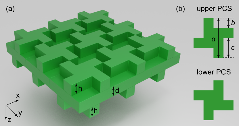
To demonstrate the possibility of vertical radiative routing of spin-polarized light sources, we consider a periodic silicon membrane with a chiral morphology (see Fig. 1). It consists of a homogeneous slab of thickness sandwiched between two photonic crystal slabs of equal thicknesses . The upper and lower photonic crystal slabs are mirror symmetric with respect to the the vertical mirror plane. We will demonstrate that such a D4 symmetrical structure can be a perfect photonic router. The spin-polarized light sources are simulated by spinning point dipoles, i.e., by the classical model of radiating molecules or quantum dots undergoing a spin-polarized transition.
II Theoretical method
In this work, we use the Fourier modal method in the scattering matrix form Tikhodeev et al. (2002) (also known as Rigorous Coupled Wave Analysis Moharam et al. (1995)) to calculate the optical properties of a chiral metamembrane. The power flow of dipole’s radiation through the horizontal planes at immediately opposite sides of the metamembrane is calculated as a -projection of the Poynting vector integrated over the structure period. In momentum space it is replaced with summation over the Floquet-Fourier harmonics:
| (1) |
where and are the vectors of Floquet-Fourier components of - and - projections of electric and magnetic vectors of dipole’s radiation field, is the speed of light and dagger denotes the conjugate transpose. According to the Fourier modal method formalism, and are found from the vectors of amplitudes by means of the material matrix :
| (2) |
where indices u and d mean that corresponding quantities are taken in the substrate or superstrate; is the zero vector of the same size as and , the outgoing hypervectors which can be found by the method of oscillating currents Whittaker and Culshaw (1999); Whittaker (2000); Taniyama and Notomi (2008); Lobanov et al. (2012); Fradkin et al. (2019):
| (3) | ||||
| (4) |
In equations (3-4) are the upper and lower partial scattering matrices Tikhodeev et al. (2002); Lobanov et al. (2012) calculated at a given frequency and emission angle; and are the hypervectors of oscillating dipole’s current that are found from its Floquet-Fourier components , and by the use of the material matrix of the layer where the dipole is located:
| (5) |
Here is the 33 block matrix with components that evolve from the Fourier transform of dielectric permittivity tensor Weiss et al. (2009) calculated in accordance with Li’s factorization rules Li (1997); are the diagonal matrices of - and -components of photon quasimomentum vector of different diffraction orders; is the photon wavenumber in vacuum.
To simulate the emission of a rotating point dipole positioned at a spatial coordinate in terms of the Fourier modal method, we calculate the harmonics of current () as
| (6) |
where are the components of current in real space, is the in-plane wavevector, is the basis of vectors in reciprocal space, and are integers. The current is set as where the sign "+" (or "-") corresponds to a counterclockwise (or clockwise) rotating dipole moment seen from the positive -direction. We denote the corresponding dipoles as and , respectively.
In what follows, we normalize the radiation power flux from a dipole in membrane to the radiation power flux from the same dipole in free space: ; we define this ratio as an emissivity.
We use the dielectric permittivity of Si from Ref. Palik and Ghosh, 1998.
III Results
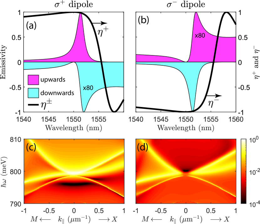
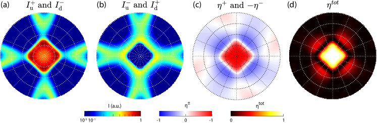
The calculated normalized emissivity of and rotating dipoles located in the center of the unit cell of the optimized chiral metamembrane in directions up and down perpendicular to the structure are shown in Fig. 2(a,b). Figures 2(c,d) show the calculated frequency and in-plane wavenumber (in directions and ) dependencies of the normalized emissivity in directions up and down of or rotating dipoles summed over both polarization states of the emitted light. The emissivity of the optimized chiral metamembrane in a wider energy-wavenumber range is shown in Fig. S1 of the Supplemental Material(SM) 111See Supplemental materials at http://link.aps.org/supplemental/xxx for the emissivity of the optimized chiral metamembrane in a wider energy-wavenumber range.. Note that all panels of Fig. 2 show the emissivity which is normalized to its maximum which is . This nearly two orders of magnitude enhancement is due to the Fano resonance effect discussed below.
Interestingly, the momentum dependence of the emissivity downwards near -point in Fig. 2(d) looks very much like a typical behaviour of the symmetry-protected bound state in continuum (BIC), see, e. g., in Ref. Sadrieva et al., 2019 and references therein. However, here the emission vanishes in the downwards direction only, and for the dipole. Whereas it is open and resonantly enhanced in the opposite direction, upwards (see in Fig. 2(c)). Correspondingly, there is no shrinking to zero of the resonance linewidth, only a relative narrowing due to a partial closing of the emission channels. Analogous situation is well known, e. g., for higher resonances in symmetric points of the Brillouin zone when the symmetry protection works only for highly symmetric directions, whereas the diffraction channels remain open Tikhodeev et al. (2002).
One can see in Fig. 2 that for both types of dipoles, the up and down light emission is different. The structure is optimized so that at a vacuum wavelength of m the downwards emissivity of the dipole is zero while for upwards direction it is close to the maximum. To describe this asymmetry quantitatively we introduce the routing efficiencies and , as well as the total routing efficiency defined as
| (7) |
It becomes possible for the optimized metamembrane to reach , , at m. Such a perfect routing is due to the vanishing emissivities and at this wavelength which is attributed to the Fano effect. Peaks in Fig. 2 have asymmetric Fano-type shapes; they represent the quasiguided modes (also known as quasinormal guided modes Leung et al. (1994); Tikhodeev et al. (2002); Gippius et al. (2005); Muljarov et al. (2010); Kristensen and Hughes (2014); Alpeggiani et al. (2017); Lassalle et al. (2018); Lalanne et al. (2019); Gras et al. (2019)) that appear in the emission spectra due to the grating assisted coupling of the emitted light with photon continuum of the far field Fano (1941, 1961); Luk’yanchuk et al. (2010); Tikhodeev et al. (2002); Dyakov et al. (2016, 2012, 2018c).
In general, the asymmetric Fano shape appears in reflection, transmission or emissivity spectra of a photonic crystal slab as a result of interference of its eigenmode with a smooth background term Gippius et al. (2005):
| (8) |
where is the oscillator strength, is the eigenfrequency and is the damping coefficient. In the case of a pure resonance (), the complex plane trajectory of the parameter is represented by a circle arond zero and the emissivity spectrum of is a symmetric Lorentzian curve. When the spectrum becomes asymmetric and at certain geometrical parameters and frequency can be zero. When is a weak function of , Eqn. (8) is often interpreted as an interference of a discrete state with a continuum of states Luk’yanchuk et al. (2010).
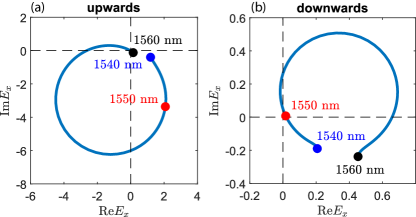
Complex plane diagrams of the -component of the electric field radiated by dipole in directions up and down are shown in Fig. 3. One can see that the relative phase of changes by a value of with an increase of from 1540 to 1560 nm. At 1550 nm for downwards emission the phase trajectory of passes through the origin while for upwards emission the zero point on the phase trajectory is relatively far from it. This results in at this wavelength. For 1553.6 nm the situation is opposite and too. Similar diagrams can be obtained for the .
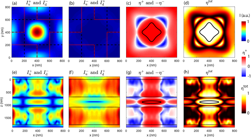
For the practical realization, it is interesting to study the stability of this effect relative to the dipole position. The dependencies of the emissivity in directions up and down on the dipole’s position within the horizontal and vertical planes which pass through the center of the cell are shown in Fig. 4. The corresponding dependencies for the dipoles are the same (not shown), however, one must swap the directions up and down. One can see that these dependencies have maximum and minimum in the central region of the cell. In this region the emission of (or ) dipole is not coming out in downwards (or upwards) direction and the corresponding routing efficiency is (or ). There are also the local minima from where the emission in directions up or down is sufficiently suppressed, however, it is not strictly zero, so that . The resulting dependencies of the routing efficiencies on the dipole position consist of regions with positive and negative values (Fig. 4(c,g)). Figure 4(d,h) shows the total routing efficiency, solid lines bound the regions with . One can see that efficient routing is possible for dipoles located in rather a large volume of the unit cell. If a quantum dot undergoing the spin-polarized transition is placed within this volume, its upwards or downwards emission will be strongly suppressed.
IV Discussion
In this work as a proof of principle of routing the emission of spinning dipoles, we use the structure with D4 rotational symmetry (Fig. 1). Let us now demonstrate that for the effect of a perfect routing the D4 symmetry is more suitable than C4 which is often used to obtain circular dichroism. The structure in Fig. 1 would have the C4 symmetry if it was on the substrate or if it had only one of the chiral photonic crystal slabs.
We start our discussion with C4 symmetrical structures as it is a more general case. We consider the electric field generated by an oscillating dipole located in the middle of the cell in the -plane at an arbitrary -coordinate. The electric field is considered below and above the membrane. We denote the complex-valued electric field components produced by the -polarized dipole moment as
| (9) |
For the C4 symmetrical structures, the fields generated by the -polarized dipole moment have the form:
| (10) |
By the superposition principle, the electric fields from the and polarized dipoles are found as
| (11) |
With the simultaneous fulfillment of the conditions
| (12) |
the emission intensities from dipoles in downwards direction and dipoles in upwards direction are zeros and the resulting total routing coefficient . The electric field components , , , depend on geometrical parameters of the metamembrane and it can be problematic to simultaneously fulfill the above two conditions in structures with C4 symmetry. Whereas the D4 symmetrical structures, such as shown in Fig. 1, have one more symmetry operation under which the structure is invariant, namely the rotation by 180∘ about the -axis (or equivalent -axis). It leads to the fact that a dipole, located in the center of the cell of any D4 symmetrical structure, generates electric field such that and . It makes the conditions (12) equivalent to each other. Thus, for D4 symmetrical structures the condition for the perfect routing is expressed only by one equality which is much easier to satisfy than both of equalities (12) simultaneously. See Fig. S2 in SM at 222See Supplemental Material at http://link.aps.org/supplemental/xxx for dependencies of the total routing coefficient on the geometrical parameters of the chiral metamembrane. for dependencies of on the geometrical parameters. Using this condition we obtain that in D4 symmetrical structures the emission from and dipoles is circularly polarized:
| (13) |
From (13) it follows that the upwards emission from dipole and the downwards emission from dipole both have the same helicity such that an observer looking in the direction from which the light is coming, sees the electric vector describing the circle in the counterclockwise sense. By the simultaneous change of the sign of the right hand side in Eqn. 12, one can obtain the condition for the opposite helicity of radiated light: . In the described chiral metamembrane, the conditions are fulfilled at m and m, respectively. It is noteworthy that the directions of electric vector rotation and dipole’s rotation are the same.
V Conclusion
In conclusion, we have theoretically demonstrated the chiral metamembrane with the highest possible circular dichroism of the light emission of clockwise and counterclockwise rotating electric dipoles. In the optimized for optical communication wavelength 1.55 m structure, the dipole radiates light entirely upwards while the dipole radiates entirely downwards. We attribute this effect to the appearance of Fano resonance which occurs due to the grating assisted coupling of guided modes with far-field. We have shown the advantage of D4 symmetric structure for the achievement of this effect. This phenomenon can find application in spintronics as a spin-selective photonic router.
VI Acknowledgments
This work was supported by the Russian Science Foundation (Grant №16-12-10538).
References
- Bliokh et al. (2015) K. Y. Bliokh, F. J. Rodríguez-Fortuño, F. Nori, and A. V. Zayats, Nature Photonics 9, 796 (2015).
- Lodahl et al. (2017) P. Lodahl, S. Mahmoodian, S. Stobbe, A. Rauschenbeutel, P. Schneeweiss, J. Volz, H. Pichler, and P. Zoller, Nature 541, 473 (2017).
- Chong et al. (2020) A. Chong, C. Wan, J. Chen, and Q. Zhan, Nature Photonics , 1 (2020).
- Abujetas and Sánchez-Gil (2020) D. R. R. Abujetas and J. A. Sánchez-Gil, ACS Photonics (2020).
- Wei and Rodríguez-Fortuño (2020) L. Wei and F. J. Rodríguez-Fortuño, Physical Review Applied 13, 014008 (2020).
- Zambon et al. (2019) N. C. Zambon, P. St-Jean, M. Milićević, A. Lemaître, A. Harouri, L. Le Gratiet, O. Bleu, D. Solnyshkov, G. Malpuech, I. Sagnes, et al., Nature Photonics 13, 283 (2019).
- Bliokh et al. (2019) K. Y. Bliokh, M. A. Alonso, and M. R. Dennis, Reports on Progress in Physics 82, 122401 (2019).
- Tsesses et al. (2019) S. Tsesses, K. Cohen, E. Ostrovsky, B. Gjonaj, and G. Bartal, Nano letters 19, 4010 (2019).
- Woźniak et al. (2019) P. Woźniak, I. De Leon, K. Höflich, G. Leuchs, and P. Banzer, Optica 6, 961 (2019).
- Wang et al. (2019) Z. Wang, Y. Wang, G. Adamo, J. Teng, and H. Sun, Laser & Photonics Reviews 13, 1800276 (2019).
- Dyakov et al. (2018a) S. Dyakov, V. Semenenko, N. Gippius, and S. Tikhodeev, Physical Review B 98, 235416 (2018a).
- Dyakov et al. (2018b) S. A. Dyakov, A. V. Ignatov, S. G. Tikhodeev, and N. A. Gippius, in Journal of Physics: Conference Series, Vol. 1092 (IOP Publishing, 2018) p. 012028.
- Zanotto et al. (2019) S. Zanotto, G. Mazzamuto, F. Riboli, G. Biasiol, G. C. La Rocca, A. Tredicucci, and A. Pitanti, Nanophotonics 8, 2291 (2019).
- Zanotto et al. (2020) S. Zanotto, A. Tredicucci, D. Navarro-Urrios, M. Cecchini, G. Biasiol, D. Mencarelli, L. Pierantoni, and A. Pitanti, Advanced Optical Materials 8, 2070016 (2020).
- Luxmoore et al. (2013) I. J. Luxmoore, N. A. Wasley, A. J. Ramsay, A. C. T. Thijssen, R. Oulton, M. Hugues, S. Kasture, V. G. Achanta, A. M. Fox, and M. S. Skolnick, Phys. Rev. Lett. 110, 037402 (2013).
- Lin et al. (2013a) J. Lin, J. P. B. Mueller, Q. Wang, G. Yuan, N. Antoniou, X.-C. Yuan, and F. Capasso, Science 340, 331 (2013a).
- Shitrit et al. (2013a) N. Shitrit, I. Yulevich, E. Maguid, D. Ozeri, D. Veksler, V. Kleiner, and E. Hasman, Science 340, 724 (2013a).
- Lin et al. (2013b) J. Lin, J. B. Mueller, Q. Wang, G. Yuan, N. Antoniou, X.-C. Yuan, and F. Capasso, Science 340, 331 (2013b).
- Shitrit et al. (2013b) N. Shitrit, I. Yulevich, E. Maguid, D. Ozeri, D. Veksler, V. Kleiner, and E. Hasman, Science 340, 724 (2013b).
- Kapitanova et al. (2014) P. V. Kapitanova, P. Ginzburg, F. J. Rodríguez-Fortuño, D. S. Filonov, P. M. Voroshilov, P. A. Belov, A. N. Poddubny, Y. S. Kivshar, G. A. Wurtz, and A. V. Zayats, Nature Communications 5, 4226 (2014).
- Petersen et al. (2014) J. Petersen, J. Volz, and A. Rauschenbeutel, Science 346, 67 (2014).
- Mitsch et al. (2014) R. Mitsch, C. Sayrin, B. Albrecht, P. Schneeweiss, and A. Rauschenbeutel, Nat. Commun 5, 5713 (2014).
- Spitzer et al. (2018) F. Spitzer, A. N. Poddubny, I. A. Akimov, V. F. Sapega, L. Klompmaker, L. E. Kreilkamp, L. V. Litvin, R. Jede, G. Karczewski, M. Wiater, T. Wojtowicz, D. R. Yakovlev, and M. Bayer, Nature Physics 14, 1043 (2018).
- Liu et al. (2019) W. Liu, V. M. Menon, S. Gao, and G. S. Agarwal, Phys. Rev. B 100, 245428 (2019).
- Fernandez-Corbaton et al. (2019) I. Fernandez-Corbaton, C. Rockstuhl, P. Ziemke, P. Gumbsch, A. Albiez, R. Schwaiger, T. Frenzel, M. Kadic, and M. Wegener, Advanced Materials 31, 1807742 (2019).
- Feis et al. (2020) J. Feis, D. Beutel, J. Köpfler, X. Garcia-Santiago, C. Rockstuhl, M. Wegener, and I. Fernandez-Corbaton, Physical Review Letters 124, 033201 (2020).
- Lei et al. (2020) F. Lei, G. Tkachenko, X. Jiang, J. M. Ward, L. Yang, and S. N. Chormaic, ACS Photonics 7, 361 (2020).
- Sinev et al. (2020) I. S. Sinev, F. E. Komissarenko, I. V. Iorsh, D. V. Permyakov, A. K. Samusev, and A. A. Bogdanov, ACS Photonics (2020).
- Tikhodeev et al. (2002) S. G. Tikhodeev, A. L. Yablonskii, E. A. Muljarov, N. A. Gippius, and T. Ishihara, Phys. Rev. B 66, 045102 (2002).
- Moharam et al. (1995) M. Moharam, T. Gaylord, E. B. Grann, and D. A. Pommet, JOSA a 12, 1068 (1995).
- Whittaker and Culshaw (1999) D. Whittaker and I. Culshaw, Physical Review B 60, 2610 (1999).
- Whittaker (2000) D. Whittaker, Optics letters 25, 779 (2000).
- Taniyama and Notomi (2008) H. Taniyama and M. Notomi, J. Appl. Phys. 103, 083115 (2008).
- Lobanov et al. (2012) S. Lobanov, T. Weiss, D. Dregely, H. Giessen, N. Gippius, and S. Tikhodeev, Physical Review B 85, 155137 (2012).
- Fradkin et al. (2019) I. M. Fradkin, S. A. Dyakov, and N. A. Gippius, Physical Review B 99, 075310 (2019).
- Weiss et al. (2009) T. Weiss, N. a. Gippius, S. G. Tikhodeev, G. Granet, and H. Giessen, J. Opt. A 11, 114019 (2009).
- Li (1997) L. Li, JOSA A 14, 2758 (1997).
- Palik and Ghosh (1998) E. D. Palik and G. Ghosh, Handbook of optical constants of solids, Vol. 3 (Academic press, 1998).
- Note (1) See Supplemental materials at http://link.aps.org/supplemental/xxx for the emissivity of the optimized chiral metamembrane in a wider energy-wavenumber range.
- Sadrieva et al. (2019) Z. F. Sadrieva, M. A. Belyakov, M. A. Balezin, P. V. Kapitanova, E. A. Nenasheva, A. F. Sadreev, and A. A. Bogdanov, Phys. Rev. A 99, 053804 (2019).
- Leung et al. (1994) P. T. Leung, S. Y. Liu, and K. Young, Phys. Rev. A 49, 3057 (1994).
- Gippius et al. (2005) N. Gippius, S. Tikhodeev, and T. Ishihara, Phys. Rev. B 72, 045138 (2005).
- Muljarov et al. (2010) E. A. Muljarov, W. Langbein, and R. Zimmermann, EPL- 92, 50010 (2010).
- Kristensen and Hughes (2014) P. T. Kristensen and S. Hughes, ACS Photonics 1, 2 (2014), https://doi.org/10.1021/ph400114e .
- Alpeggiani et al. (2017) F. Alpeggiani, N. Parappurath, E. Verhagen, and L. Kuipers, Phys. Rev. X 7, 021035 (2017).
- Lassalle et al. (2018) E. Lassalle, N. Bonod, T. Durt, and B. Stout, Opt. Lett. 43, 1950 (2018).
- Lalanne et al. (2019) P. Lalanne, W. Yan, A. Gras, C. Sauvan, J.-P. Hugonin, M. Besbes, G. Demésy, M. D. Truong, B. Gralak, F. Zolla, A. Nicolet, F. Binkowski, L. Zschiedrich, S. Burger, J. Zimmerling, R. Remis, P. Urbach, H. T. Liu, and T. Weiss, J. Opt. Soc. Am. A 36, 686 (2019).
- Gras et al. (2019) A. Gras, W. Yan, and P. Lalanne, arXiv preprint arXiv:1905.12359 (2019).
- Fano (1941) U. Fano, J. Opt. Soc. Am. 31, 213 (1941).
- Fano (1961) U. Fano, Phys. Rev. 124, 1866 (1961).
- Luk’yanchuk et al. (2010) B. Luk’yanchuk, N. I. Zheludev, S. A. Maier, N. J. Halas, P. Nordlander, H. Giessen, and C. T. Chong, Nature Mat. 9, 707 (2010).
- Dyakov et al. (2016) S. A. Dyakov, D. M. Zhigunov, A. Marinins, M. R. Shcherbakov, A. A. Fedyanin, A. S. Vorontsov, P. K. Kashkarov, S. Popov, M. Qiu, M. Zacharias, S. G. Tikhodeev, and N. A. Gippius, Phys. Rev. B 93, 205413 (2016).
- Dyakov et al. (2012) S. A. Dyakov, A. Baldycheva, T. S. Perova, G. V. Li, E. V. Astrova, N. A. Gippius, and S. G. Tikhodeev, Phys. Rev. B 86, 115126 (2012).
- Dyakov et al. (2018c) S. A. Dyakov, D. M. Zhigunov, A. Marinins, O. A. Shalygina, P. P. Vabishchevich, M. R. Shcherbakov, D. E. Presnov, A. A. Fedyanin, P. K. Kashkarov, S. Popov, et al., Scientific reports 8, 4911 (2018c).
- Note (2) See Supplemental Material at http://link.aps.org/supplemental/xxx for dependencies of the total routing coefficient on the geometrical parameters of the chiral metamembrane.