Hybrid topological guiding mechanisms for
photonic crystal fibers
Abstract
We create hybrid topological-photonic localisation of light by introducing concepts from the field of topological matter to that of photonic crystal fiber arrays. S-polarized obliquely propagating electromagnetic waves are guided by hexagonal, and square, lattice topological systems along an array of infinitely conducting fibers. The theory utilises perfectly periodic arrays that, in frequency space, have gapped Dirac cones producing band gaps demarcated by pronounced valleys locally imbued with a nonzero local topological quantity. These broken symmetry-induced stop-bands allow for localised guidance of electromagnetic edge-waves along the crystal fiber axis. Finite element simulations, complemented by asymptotic techniques, demonstrate the effectiveness of the proposed designs for localising energy in finite arrays in a robust manner.
1 Introduction
Photonic crystal fibers (PCFs) guide light by corralling it within a periodic array of microscopic air holes, or dielectric inclusions, that run along the entire fiber length [1, 2, 3, 4]. Largely through their ability to overcome the limitations of conventional fiber optics, for example by permitting low-loss guidance of light in a hollow core, these fibers have important technological and scientific applications spanning many disciplines [4, 5, 6, 7]. The result has been a renaissance of interest in optical fibers, and their uses, over the past two decades as reviewed in [8, 9]; this activity has also strongly influenced acoustics through the developing field of phononic crystals [10].
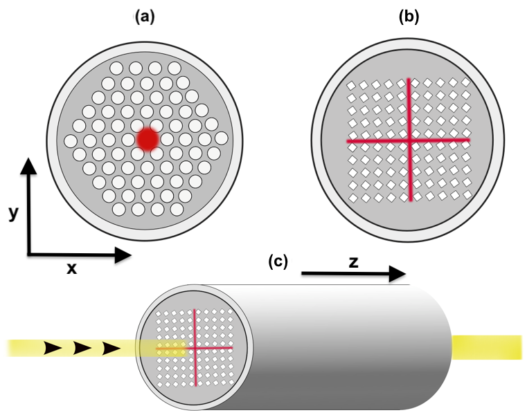
Recently, ideas originating from topological insulators [11] have been transposed into photonics [12], as reviewed in [13], showing promise for robust one-way edge states with enhanced protection against disorder. In Newtonian systems, this promise of topological protection is tempered by the requirement for time reversal symmetry (TRS) to be broken. An alternative, simpler approach, all be it resulting in less robust modes, is to leverage the pseudospins inherent within specific continuum systems. These pseudospin modes arise from strategically gapping Dirac cones to leave two pronounced valleys with locally quadratic curvature. This approach, commonly referred to as valleytronics [14, 15, 16, 17], is associated with the quantum valley-Hall effect in condensed matter physics. It has already been utilised in many settings, including the creation of dielectric photonic topological arrangements, leading to reflectionless guiding and designs for optical delay lines [18]. Topological designs have also been recently implemented for telecommunication wavelengths [19] on a CMOS-compatible chip thus bringing these concepts closer to application. These valley-Hall devices are locally topologically nontrivial however globally trivial, and therefore cannot draw upon the full power of the analogy with topological insulators, but they do have advantages in terms of their simplicity of construction as one needs only to break spatial inversion or reflectional symmetries, together with actively suppressing backscattering. Symmetries are central to optical waveguide theory [20], and have a long history within the field, and the topological guidance also draws upon symmetries and its mathematical language of group theory. Given the emergence of topological guiding there is now interest in developing this for photonic circuits, [21], and for Bragg fibres [22] by manipulating the cladding [23], and there is a natural drive to explore the potential of these new ideas in other arenas. Our aim here is to demonstrate the viability of valleytronics to create localization of light for guidance in PCFs and to create a hybrid topological-PCF using these valley-Hall topological concepts (Fig. 1).
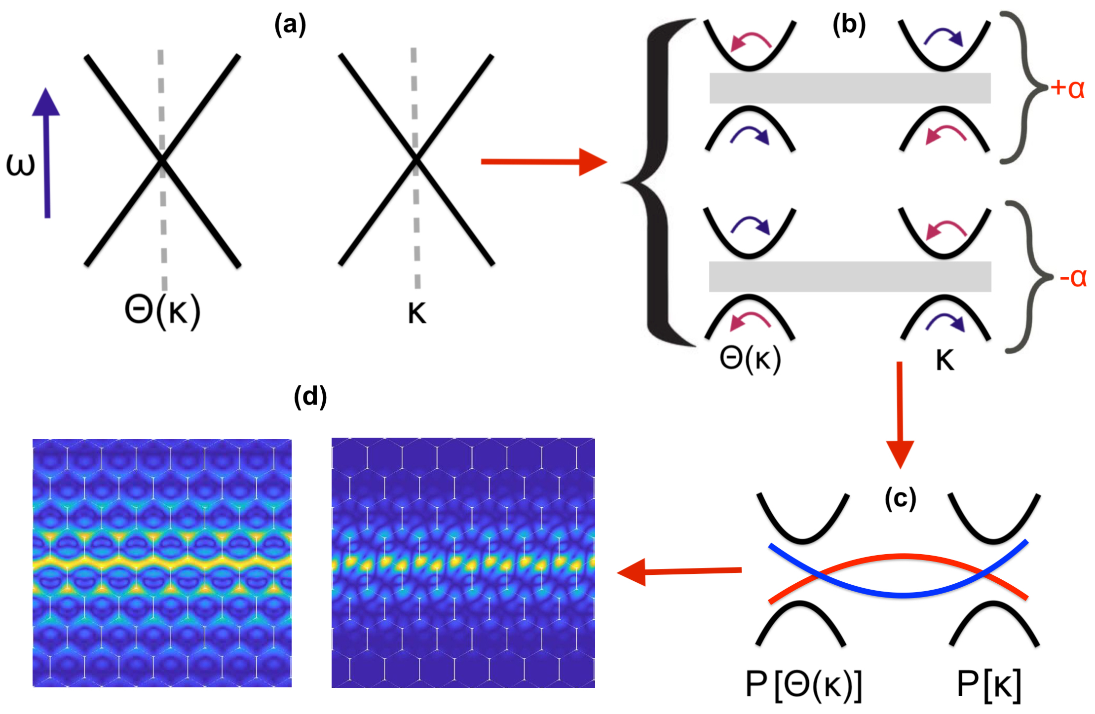
After summarising our problem formulation in Sec. 2 we begin in Sec. 3, by considering an infinite periodic photonic crystal with inclusions placed on a hexagonal or square lattice. The periodicity means that we can consider a single elementary cell and use Floquet-Bloch theory to generate an understanding of the system; dispersion curves that relate the frequency to Bloch wave-vector, portrayed around the edges of the Brillouin zone, encode the essential information about the system. We use our knowledge of symmetries in topological systems to obtain Dirac cones, the chosen inclusions are then perturbed to gap the Dirac cones and thereby create band-gaps. Interfacial modes within the band-gaps, that benefit from topological concepts, are then used to develop the hybrid topological-PCFs. The steps to arrive at the localised edge-states, using topological ideas, are summarised in Fig. 2. These PCFs are investigated numerically, for finite array PCFs, in Sec. 4 and we use finite element methods, and augment these numerics with a semi-analytic method based around induced monopole and dipole scattering by small cylinders suitable for open systems.
2 Formulation
Although the harmonic Maxwell’s equations (we assume dependence understood throughout) are inherently coupled, [25], provided one assumes infinite conducting boundary conditions, i.e. metallic fibers, along the fiber’s axis [26, 4], the guided modes within a fiber decouple naturally into and polarizations. We consider an array of such fibers, see Fig. 1, with periodicity in the -plane, and focus on the latter polarization. Taking into account the invariance of the fiber array along its -axis, we look, for a given propagation constant , for eigenfrequencies, , and eigenmodes, , such that
| (1) |
where , with () as the permittivity and permeability in-vacuum (and relative values); is angular frequency.
In general, for oblique wave incidence down a PCF, we are faced with a fully-coupled vector electromagnetic problem [4] but, as noted above, in the case of crystal fibers with infinite conducting boundary conditions (a model for microwaves, or for light in dielectric fibers propagating with large propagation constant [27]), (1) simplifies into
| (2) |
where , and is the longitudinal component of . Eq. (2) has the condition , on each fiber’s boundary, where is the unit outward normal to this boundary in the -plane.
An aside is that there is an equivalent phononic crystal fiber analogy: the same eigenvalue problem holds for time-harmonic scalar pressure acoustic waves propagating at an oblique angle guided along an array of rigid fibers:
| (3) |
with () as the mass density and compressibility modulus in air (and relative values), .
We naturally focus on PCFs, but note that our results hold for both time-harmonic electromagnetic waves in polarization, and pressure acoustic waves in phononics, propagating at an oblique angle within crystal fibers (with infinite conducting walls for the former, and rigid walls for the latter). As we consider a periodic assembly of fibers, we use a normalised frequency, , hereafter, where is the pitch of the lattice and the speed of light ( assuming ), or sound () in the medium surrounding the fibers.
3 Symmetry protected topological states in hexagonal and square structures
By considering an infinite array of identical parallel fibers we restrict our initial analysis to either a hexagonal or square elementary cell, containing a single or multiple fibers, that is then periodically repeated. For a given propagation constant , we find Floquet-Bloch waves such that
| (4) |
with as the Bloch wavevector, as the position vector and as the vector attached to the nodes of the lattice of translation vectors and , which form the basis for the lattice as a whole; in this article we consider square and hexagonal lattices. We proceed by numerically solving the spectral problem (2)-(4) using the finite element package Comsol Multiphysics [28] to compute the eigenfrequencies and associated Bloch eigensolutions when spans the Brillouin zone (BZ) in the reciprocal space. These finite element numerics are complemented by a semi-analytic method based around monopolar and dipolar scattering by small metallic cylinders, the details of which are in [29] and covered briefly in Appendix A.
These eigenfrequencies form a discrete spectrum , , and noting that in (2) it is easily seen [4] that these are bounded below with
| (5) |
and, as the propagation constant varies, dispersion curves can be drawn.
3.1 Hexagonal structures
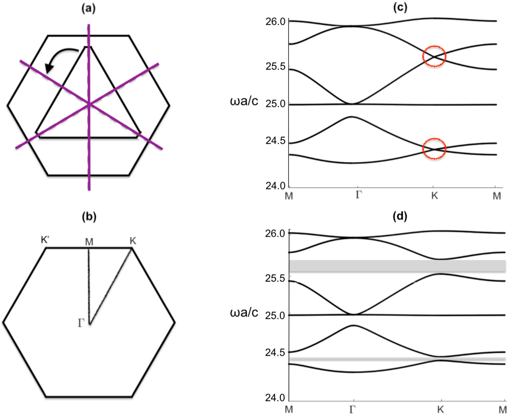
TRS topological-PCFs leverage the discrete valley degrees of freedom that arise from degenerate extrema in Fourier space (Fig. 2). When constructing these PCFs we draw upon the valleytronics literature that, motivated by graphene, takes advantage of symmetry induced Dirac cones at the vertices of the hexagonal BZ, see Fig. 3(b, c) [24, 30]. These Dirac degeneracies are guaranteed if the structure belongs to one of three different symmetry sets [24]: , where denote the point group symmetries [31, 32, 33] at and , respectively. We have chosen to illustrate the hexagonal topological PCFs using two of these cases and . Turning to the case first, shown in Fig. 3(a), we gap the Dirac cone, and reduce the symmetry of the structure, down to by rotating the internal inclusion. The resulting band gap (Fig. 3(b)) is demarcated by two regions of locally quadratic curvature commonly referred to as “valleys". These valleys are imbued with a nonzero (local) topological quantity known as the valley Chern number; the opposite sign of the valley Chern numbers at the upper and lower valleys leads to the generation of topological edge modes [34, 30]. Importantly, the valleys have opposite chirality (or angular momenta) and are related by parity and/or reflectional symmetry as well as TRS. A clear demonstration in the context of photonics for delay lines is in [18], and for numerical convenience we adopted their truncated triangular inclusion. Despite this, we are not limited to using solely a triangular geometry for our fibre, as we may use any cellular structure that belongs to one of the three aforementioned Dirac cone inducing symmetry groups. To illustrate this further we also consider a geometry created from an arrangement of metallic cylinders.
Infinite array of small circular perfectly conducting cylinders
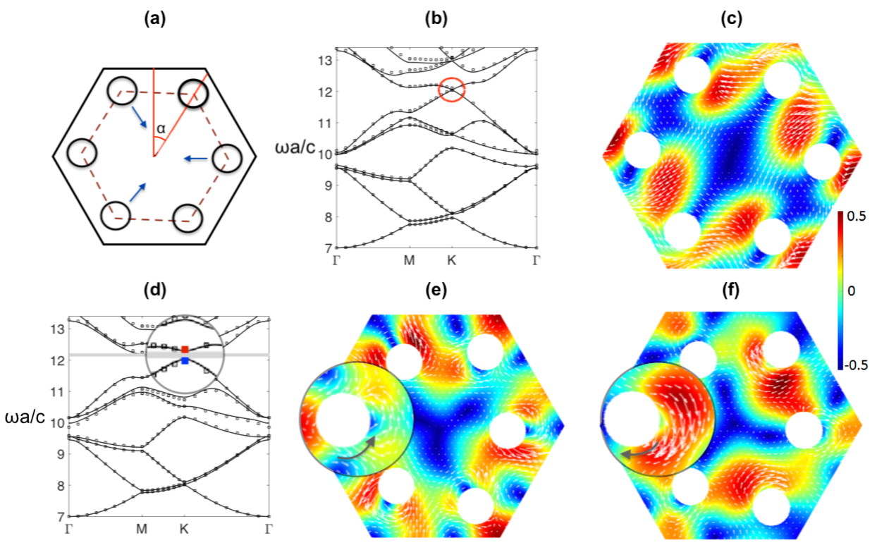
We demonstrate how a different hexagonal geometry, Fig. 4(a), that belongs to a different symmetry set and uses circular inclusions, yields a topologically nontrivial band gap. The fabrication of circular fibres is easier than that of polygonal inclusions, and to emphasise the generality of the topological concepts we use circular inclusions arranged around a hexagonal perimeter. We opt to use an alternative semi-analytical approach that is less computationally expensive than directly using finite element methods and which is relevant to open systems. This method is explained in detail in [29] and is briefly summarised in Appendix A. The usefulness of this semi-analytical scheme will become apparent in Sec. 4 when we design more complex topological PCFs.
The geometry under consideration, Fig. 4(a), consists of several small, but finite radius, circular inclusions, located at the vertices of a hexagon. This smaller hexagon is contained entirely within the larger hexagonal cell and is rotated relative to it by an angle of . This unperturbed arrangement belongs to the symmetry set and produces the dispersion curves shown in Fig. 4(b). By strategically perturbing the cellular structure (see arrows in Fig. 4(c)) the point group symmetry at is reduced down to . This perturbation gaps the former Dirac cone to yield the band gap shown in Fig. 4(c) and we use the recipe outlined in Fig. 2. The eigenstates, that sit at the blue and red marked valleys in Fig. 4(c), are illustrated in Fig. 4(e, f). The chirality of these eigenstates are characterised by the time-averaged energy flux, defined as,
| (6) |
where denotes the complex conjugate. The magnifications in Figs. 4(e, f) demonstrates the opposite chirality (or angular momenta) between the pair of eigenstates. This angular momenta difference is a foundational property that predicates the generation of the topological edge states in Sec. 3.3.
3.2 Square structure
Symmetry protected Dirac cones can also be constructed for non-hexagonal systems [36, 37, 38, 39, 40]. Notably a strategically designed square (or rectangular) structure allows for the emergence of mirror symmetry protected Dirac cones; these systems differ from the vast majority of earlier valleytronic literature [41, 42, 43, 44, 45, 46, 47, 24, 48] that have focused on graphene-like structures.
The unrotated cellular structure we choose, shown in Fig. 5(a), contains, both, horizontal and vertical mirror symmetries along with four-fold rotational symmetry. These mirror symmetry lines are responsible for the highlighted Dirac cones located along the paths and in Figs. 5(b, c) [36]. Unlike hexagonal structures, the position of these degeneracies can be tuned by varying the geometrical or material parameters of the system [36]. Despite the IBZ for this structure being an eighth of the BZ, rather than a quarter, we plot around a quadrant of the BZ, Fig. 5(b), as this incorporates the two distinct Dirac cones that are essential for our topological states. The desired quadrant has the following vertices: , , , , where is the lattice constant. The dispersion diagram, plotted around the IBZ, as well as a discussion about the influence of the diagonal mirror symmetries is in Appendix B.
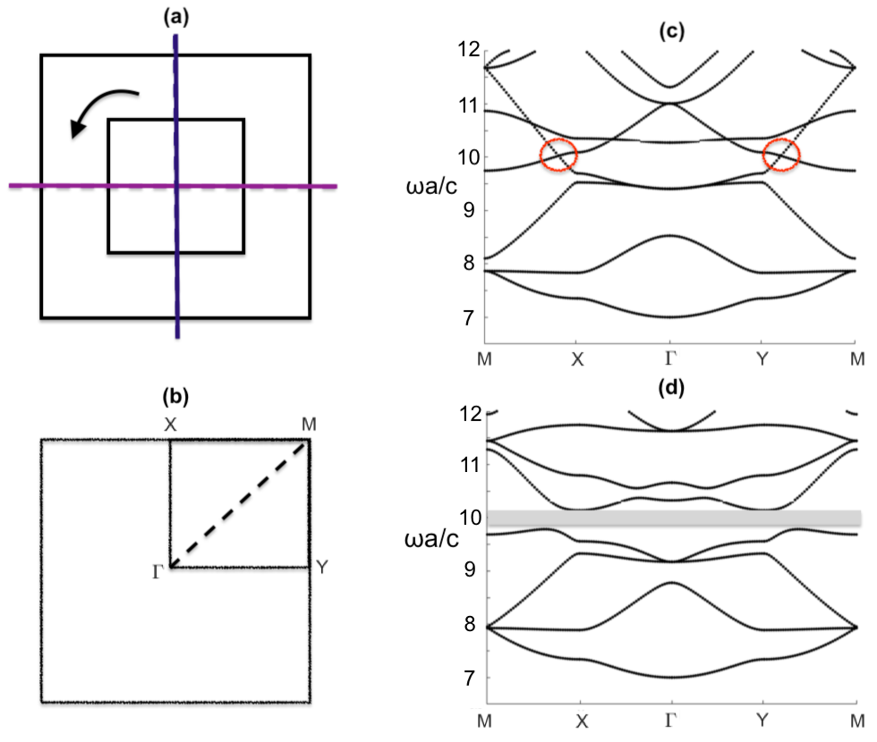
The breaking of all sets of mirror symmetries, via the rotation of the internal square fiber, leads to the topologically nontrivial band gap shown in Fig. 5(c). The two residual valleys along each of the vertical and horizontal edges of the BZ are imbued with opposite sign valley Chern numbers. This difference in sign physically manifests itself as a difference in chirality between the valley eigenstates; this crucial property will be used in the next subsection.
3.3 1D dispersion curves and edge states
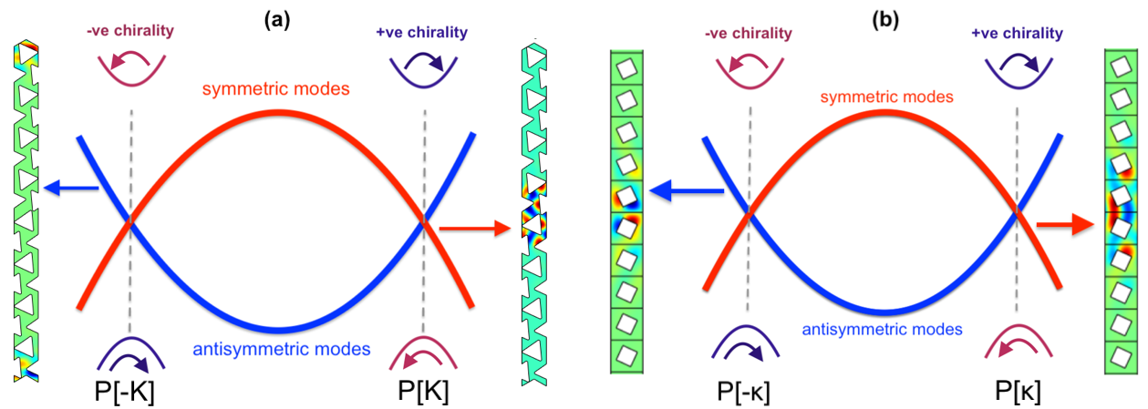
The perturbation of the bulk media has broken reflectional or rotational symmetries whilst still retaining three-fold symmetry (for the hexagonal cases) and four-fold symmetry (for the square case). By stacking oppositely perturbed media, as shown in Fig. 6, one above the other, we are able to create two seemingly distinct interfaces upon which edge states reside; due to the broken symmetries, we now have inequivalent valleys characterised by opposite valley Chern numbers. Exemplar eigenstates, for the bulk media, located near the two topologically distinct valleys are shown in Fig. 4(e, f) and notably there is a marked difference between their angular momenta in prescribed regions. Creating interfaces, as we do here, between two media that have these opposite chiralities (or angular momenta) leads to the generation of topological edge states [30, 14]; these are aptly named zero-line modes (ZLMs) due to the opposite sign of the valley Chern numbers on either side of the interface. The asymmetry, either side of the interface, leads to highly confined edge states such as those shown in Fig. 6. A benefit of these topological modes is that we have a priori knowledge of how to construct the two adjoining media (sharing a band gap) such that we are guaranteed broadband edge modes that are more impervious to disorder [49] than competing designs. There is a notable difference between the square and hexagonal ribbon eigenmodes (Fig. 6); the different parity eigenmodes belong to different interfaces for the hexagonal case and the same effective interface for the square case. This implies that a right-propagating mode along one of the square interfaces is also a left-propagating mode on the other. This nuance leads to additional functionality for square structures, absent from hexagonal structures, such as the three-way partitioning of energy away from a nodal point and the propagation of topological modes around a bend. Further discussion of this difference in behaviour between the two geometries is found in [36, 37].
Due to the absence of orthogonal spin particles and the presence of TRS, caution is needed when we engineer our structure, in order to minimise inadvertent scatter [50, 34]. There are competing mechanisms: the band gap needs to be large enough to localise the edge states near the domain wall, whilst not being so large, that the oppositely propagating modes are no longer orthogonal [51]. The band gap width tunes the robustness and this is enhanced by preserving the locally quadratic curvature in the vicinity of the gapped Dirac cones. The strength of the perturbation is directly related to the orthogonality of the counter-propagating edge states. The Fourier separation between the modes excited should also be enhanced to limit inadvertent scattering [50, 34]. Dirac cones located away from high-symmetry points, such as those of the square structure, are tunable in their position. Here, the robustness is further enhanced by artificially increasing the Fourier separation between the Dirac points which, in turn, leads to an increased separation between the forwards and backwards propagating edge modes.
Numerical studies that demonstrate the robustness of these topological states versus conventional designs for Newtonian systems are found in [49, 52, 53, 54]. Theoretical studies that demonstrate the existence of these modes under disorder are found in [55, 56]. These studies pertain to quantum topological systems where the transition across the domain wall is approximated as a smooth function. By carefully engineering our system, using the parameters at our disposal, namely, the perturbation strength, the Fourier separation and the transition across the interface, the valley has the potential to become a highly-efficient carrier of information [13].
4 Finite topological photonic crystal fiber arrays
We now consider finite photonic crystal arrays created from metallic inclusions arranged to illustrate the topological edge states. The inclusions are arranged as a finite cluster, spaced with lattice constant , and numerically we take the cluster to be surrounded by cladding.
We employ two different numerical methods, primarily we use the Finite Element package COMSOL 3.5 Multiphysics, implement equation (2) in the PDE module, and solve an eigenvalue problems with the solver for Hermitian matrices (Lanczos algorithm). For these finite element simulations we have a radial outer boundary upon which we set metallic boundary conditions. It is well-known, [4], that this metallic outer boundary allows us to estimate the real part of the eigenfrequencies of an open system, provided the outer radial boundary is sufficiently large; we systematically checked that numerical values of eigenfrequencies of modes of interest are robust against the diameter of PCFs. To further confirm that these modes persist in the case of open PCFs we also utilise a semi-analytic method, designed for the rapid simulation of small metallic cylinders that asymptotically represents them as monopole and dipole scatterers as detailed in [29] and these simulations have no outer metallic boundary.
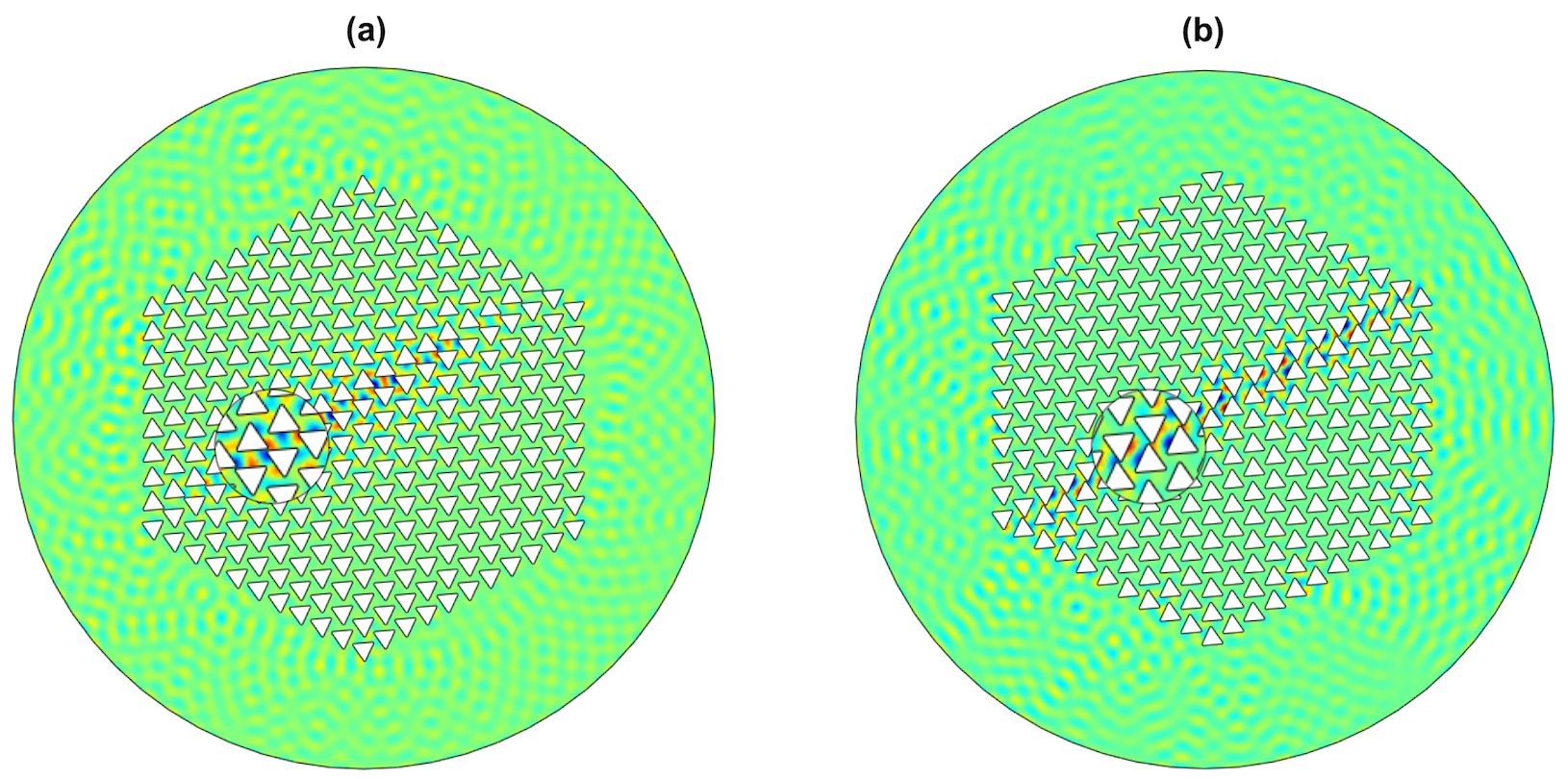
We begin with an exploration of the ZLMs, for hexagonal media, containing the simple triangular inclusion of Fig. 3, and take a hexagonal finite PCF as shown in Fig. 7. We cut this finite hexagonal array in half and rotate the inclusions in the upper/lower halves in opposite directions to form two distinct interfaces in a similar manner to Fig. 6(a); these interfaces support a pair of geometrically distinct ZLMs [24]. As noted in Sec. 3.3, for the hexagonal system the relative ordering of the medium matters and we witness this from the edge states found for Fig. 7(a) and (b), which resemble those eigenmodes in Fig. 6(a); the frequencies at which these edge states occur are reassuringly in the band gap predicted by the perturbed bulk media in Fig. 3(d). These simulations are all done with standard finite element methods, i.e. Comsol, and the finite PCF array is surrounded by cladding and an outer metallic radial boundary thereby forming a closed system.
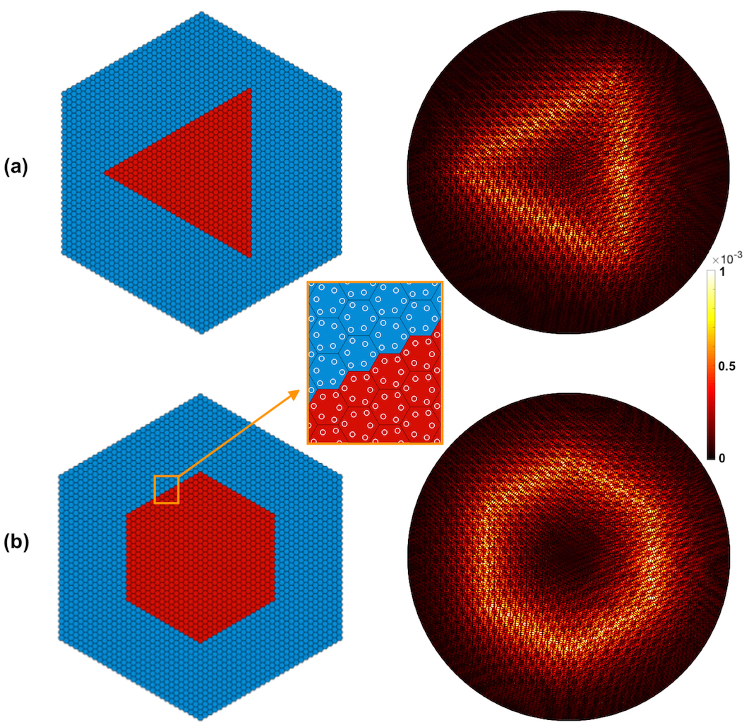
The array in Fig. 7 contains a relatively small number of scatterers, each of which is a single triangular shape, and the PCF is enclosed by a metallic outer boundary. We also want to consider more complex PCFs and explore whether we can generate topological states that remain localised around a closed polygonal boundary with limited leakage. To do so, we utilise the semi-analytical method, espoused in Appendix A, to analyse complex open systems with ease. In Fig. 8 we consider two polygonal patches, a triangle and a hexagon, that are constructed from a set of adjoining zigzag interfaces [14] in the -plane; each of these crystals are formed from multiple smaller structured cells. The result of this construction are two striking highly localised triangular (Fig. 8(a)) and hexagonal prism PCFs (Fig. 8(b)); these fields consist of the topological modal conversion and preservation phenomena emphasised in [24, 48]. Figs. 8(a, b) take advantage of the bulk band diagrams of Fig. 4, and the construction methodology outlined in Fig. 2.
The hexagonal array is the more common array type used in valleytronics, due to the guaranteed Dirac cones at the BZ vertices, but as shown earlier square arrays can also be used to create topological effects [36, 37, 38, 39, 40]; we now construct small finite square arrays of just 100 square inclusions. We consider a circular metallic PCF of radius , filled with square metallic rods of sidelength where is the array pitch. The outer boundary at is taken to be metallic in simulations and we have checked that the modes we find are independent of radius and therefore are genuine trapped modes.
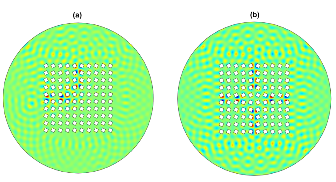
We use the geometry shown in Fig. 5, and draw upon the edge states shown in Fig. 6(b). Rather than just split a medium in half, we separate our square array into quadrants and then rotate the inclusions within each quadrant. Our motivation is to demonstrate localised topological modes, such as the bend and the four-armed cross, that are not possible when using the canonical hexagonal topological systems [36, 37]. In Fig. 9 we illustrate localised states, along the edges of these quadrants, for this square array. Notably we rotate the square inclusions by 25 degrees either clockwise or anti-clockwise in different quadrants (similar to Fig. 6(b)); panel (a) has the upper left quadrant rotated anti-clockwise and the remainder rotated clockwise, (b) has the upper left and lower right quadrants rotated anti-clockwise and the remainder rotated clockwise. As predicted from the topological theory [36, 37] we expect localised hybrid topological states to form along the interfaces between the oppositely rotated inclusion quadrants and indeed this is observed in (a,b). There is, as also expected, a very slight frequency shift going between the predictions based around the infinite perfectly period crystal and numerical simulations based around the finite PCF of just rods nonetheless this is reassuring agreement. Although we have illustrated just the odd mode in Fig. 6 there are complementary even mode solutions, see Appendix B, and indeed one can obtain combinations of these modes through cross-talk between the modes somewhat akin to that occurring in dual-core PCFs or between neighbouring open waveguides; a linear combination of odd and even modes can be induced in neighbouring waveguides, and similarly for dual core PCFs, and we can obtain similar behaviour, but now between the horizontal and vertical interfaces.
5 Conclusion
We have introduced a new type of hybrid topological photonic/phononic band gap guidance that is topologically induced and utilised PCFs of metallic fibers, where a decoupling of Maxwell’s equations occurs, to showcase the methodology and potential. Natural extensions involve moving to hollow or air-hole PCF, dielectric or hybrid PCFs and bringing topological effects into the fibre guidance of such more generalised systems. The construction of edge states using topological concepts is illustrated and follows a clear algorithm, c.f. Fig. 2, and we generated interfacial edge waves propagating along the crystal fiber axis in two simple configurations, for a square array of square fibers and a hexagonal array of triangular fibers, in the case of longitudinal electromagnetic/acoustic pressure waves. To illustrate the generality of these concepts, and because cylindrical fibers are more commonly used, these are augmented by a study using arrays of cylindrical inclusions placed at the vertices of a hexagon. Although here we have focused on infinitely conducting fibers, as this allows for a simple model, there are numerous extensions to draw upon in the topological valleytronics literature and beyond, and this will be a fruitful direction for future research. Examples include, but are not limited to, using valley vortex states or chirality locked beam-splitting [43, 57, 29], fragile topological states [58, 59], non-Hermitian topological physics [60] or even higher-order quadrupolar modes [61].
In terms of physics, extensions to fully coupled electromagnetic waves in dielectric photonic crystal fibers and also for elastodynamic waves, as well as their interplay [62] can be envisioned. Of particular interest is the case of open micro-structured waveguides, for which topological leaky modes would be associated with complex eigenfrequencies [63], and thus would propagate over finite distances along the PCF axis [64]. It will be interesting to investigate whether they display less, or comparable, energy leakage to typical defect modes in hybrid, non topological, PCFs, especially with respect to a genuine (fibre drawing tower induced), or engineered, twist [65, 66].
Acknowledgments
MM and RC thank the EPSRC for their support through grant EP/L024926/1 and EP/T002654/1 and the support of European Union H2020 FETOpen project BOHEME under grant agreement No 863179.
References
- [1] P. Russell, “Photonic crystal fibers,” \JournalTitleScience 299, 358–362 (2003).
- [2] J. Knight, “Photonic crystal fibres,” \JournalTitleNature 424, 847–851 (2003).
- [3] A. Bjarklev, J. Broeng, and A. Bjarklev, Photonic crystal fibres (Kluwer Academic Publishers, London, 2003).
- [4] F. Zolla, G. Renversez, A. Nicolet, B. Kuhlmey, S. Guenneau, and D. Felbacq, Foundations of photonic crystal fibres (Imperial College Press, London, 2005).
- [5] J. Lourtioz, A. Tchelnokov, H. Benisty, V. Berger, J. Gerard, and D. Maystre, Photonic Crystals: Towards Nanoscale Photonic Devices (Springer-Verlag, Berlin, 2005).
- [6] J. D. Joannopoulos, S. G. Johnson, J. N. Winn, and R. D. Meade, Photonic Crystals, Molding the Flow of Light (Princeton University Press, Princeton, 2008), 2nd ed.
- [7] S. Maier, Plasmonics: fundamentals and applications (Springer Science and Business Media, Berlin, 2007).
- [8] C. Markos, J. C. Travers, A. Abdolvand, B. J. Eggleton, and O. Bang, “Hybrid photonic-crystal fiber,” \JournalTitleRev. Mod. Phys. 89, 045003 (2017).
- [9] D. J. J. Hu, Z. Xu, and P. P. Shum, “Review on photonic crystal fibers with hybrid guiding mechanisms,” \JournalTitleIEEE Access 7, 67469–67482 (2019).
- [10] V. Laude, Phononic crystals: Artificial Crystals for Sonic, Acoustic, and Elastic Waves (DeGruyter, Berlin/Boston, 2015).
- [11] C. L. Kane and E. J. Mele, “Z2 Topological Order and the Quantum Spin Hall Effect,” \JournalTitlePhysical Review Letters 95, 146802 (2005).
- [12] L. Lu, J. D. Joannopoulos, and M. Soljačić, “Topological Photonics,” \JournalTitleNat. Photonics 8, 821–829 (2014).
- [13] A. B. Khanikaev and G. Shvets, “Two-dimensional topological photonics,” \JournalTitleNat. Photonics 11, 763–773 (2017).
- [14] D. Xiao, W. Yao, and Qian Niu, “Valley-Contrasting Physics in Graphene: Magnetic Moment and Topological Transport,” \JournalTitlePhysical Review Letters 99, 236809 (2007).
- [15] J. R. Schaibley, H. Yu, G. Clark, P. Rivera, J. S. Ross, K. L. Seyler, W. Yao, and X. Xu, “Valleytronics in 2D materials,” \JournalTitleNature Reviews Materials 1 (2016).
- [16] Y. Ren, X. Deng, Z. Qiao, C. Li, J. Jung, C. Zeng, Z. Zhang, and Q. Niu, “Single-valley engineering in graphene superlattices,” \JournalTitlePhysical Review B 91 (2015).
- [17] Y. Ren, Z. Qiao, and Q. Niu, “Topological Phases in Two-Dimensional Materials: A Brief Review,” \JournalTitleReports on Progress in Physics 79, 066501 (2016).
- [18] T. Ma and G. Shvets, “All-Si Valley-Hall Photonic Topological Insulator,” \JournalTitleNew J. Phys. 18, 025012 (2016).
- [19] M. I. Shalaev, W. Walasik, , A. Tsukernik, Y. Xu, and N. M. Litchinitser, “Robust topologically protected transport in photonic crystals at telecommunication wavelengths,” \JournalTitleNature Nanotechnology 14, 31– 34 (2019).
- [20] P. McIsaac, “Symmetry-induced modal characteristics of uniform waveguides. 1. summary of results,” \JournalTitleIEEE Trans. MicrowaveTheory Tech. MIT 23, 421–429 (1975).
- [21] L. Zhang, Y. Yang, M. He, H.-X. Wang, Z. Yang, E. Li, F. Gao, B. Zhang, R. Singh, J.-H. Jiang, and H. Chen, “Manipulation of valley-polarized topological kink states in ultrathin substrate-integrated photonic circuitry,” \JournalTitlearXiv: 1805.03954v2 p. 15 (2018).
- [22] P. Yeh, A. Yariv, and E. Marom, “Theory of Bragg fiber,” \JournalTitleJ. Opt. Soc. Am. 68, 1196–1201 (1978).
- [23] L. Pilozzi, D. Leykam, Z. Chen, and C. Conti, “Topological photonic crystal fibers and ring resonators,” \JournalTitleOpt. Lett. 45, 1415–1418 (2020).
- [24] M. P. Makwana and R. V. Craster, “Geometrically navigating topological plate modes around gentle and sharp bends,” \JournalTitlePhysical Review B 98, 184105 (2018).
- [25] J. D. Jackson, Classical electrodynamics (Wiley, New York, NY, 1999), 3rd ed.
- [26] S. Guenneau, A. Nicolet, C. Geuzaine, F. Zolla, and A. Movchan, “Comparisons of finite element and Rayleigh methods for the study of conical Bloch waves in arrays of metallic cylinders,” \JournalTitleCOMPEL pp. 932–949 (2004).
- [27] S. Guenneau, C. G. Poulton, and A. B. Movchan, “Oblique propagation of elecromagnetic and elastodynamic waves for an array of cylindrical fibres,” \JournalTitleProc. Roy. Soc. Lond. A 459, 2215–2263 (2003).
- [28] COMSOL, www.comsol.com (2018).
- [29] R. Wiltshaw, M. P. Makwana, and R. V. Craster, “Asymptotic approximations for bloch waves and topological mode steering in a planar array of neumann scatterers,” \JournalTitlearXiv:2003.10876v2 [cond-mat, physics:physics] (2020). ArXiv:2003.10876v2.
- [30] T. Ochiai, “Photonic realization of the (2+1)-dimensional parity anomaly,” \JournalTitlePhysical Review B 86 (2012).
- [31] M. S. Dresselhaus, G. Dresselhaus, and A. Jorio, Group theory: application to the physics of condensed matter (Springer-Verlag, 2008).
- [32] K. Sakoda, Optical Properties of Photonic Crystals (Springer Verlag, 2005).
- [33] T. Inui, Y. Tanabe, and Y. Onodera, Group Theory and Its Applications in Physics (Springer-Verlag, 1990).
- [34] K. Qian, D. J. Apigo, C. Prodan, Y. Barlas, and E. Prodan, “Theory and Experimental Investigation of the Quantum Valley Hall Effect,” \JournalTitlearXiv:1803.08781 [cond-mat] (2018).
- [35] C. Barreteau, F. Ducastelle, and T. Mallah, “A bird’s eye view on the flat and conic band world of the honeycomb and kagome lattices: towards an understanding of 2d metal-organic frameworks electronic structure,” \JournalTitleJournal of Physics: Condensed Matter 29, 465302 (2017).
- [36] M. P. Makwana and G. Chaplain, “Tunable three-way topological energy-splitter,” \JournalTitleScientific Reports 9, 18939 (2019).
- [37] M. Makwana, R. Craster, and S. Guenneau, “Topological beam-splitting in photonic crystals,” \JournalTitleOptics Express 27, 16088 (2019).
- [38] M. P. Makwana, N. Laforge, R. V. Craster, G. Dupont, S. Guenneau, V. Laude, and M. Kadic, “Experimental observations of topologically guided water waves within non-hexagonal structures,” \JournalTitleApplied Physics Letters 116, 131603 (2020).
- [39] J. Kim, S. Yu, and N. Park, “Universal design platform for an extended class of photonic Dirac cones,” \JournalTitlePhys. Rev. Applied 13, 044015 (2020).
- [40] B. Xia, G. Wang, and S. Zheng, “Robust edge states of planar phononic crystals beyond high-symmetry points of Brillouin zones,” \JournalTitleJournal of the Mechanics and Physics of Solids 124, 471–488 (2019).
- [41] C. He, X. Ni, H. Ge, X.-C. Sun, Y.-B. Chen, M.-H. Lu, X.-P. Liu, and Y.-F. Chen, “Acoustic topological insulator and robust one-way transport,” \JournalTitleNature Physics 12, 3867 (2016).
- [42] H. Schomerus, “Helical scattering and valleytronics in bilayer graphene,” \JournalTitlePhysical Review B 82, 165409 (2010).
- [43] L. Ye, C. Qiu, J. Lu, X. Wen, Y. Shen, M. Ke, F. Zhang, and Z. Liu, “Observation of acoustic valley vortex states and valley-chirality locked beam splitting,” \JournalTitlePhysical Review B 95, 174106 (2017).
- [44] X. Cheng, C. Jouvaud, X. Ni, S. H. Mousavi, A. Z. Genack, and A. B. Khanikaev, “Robust reconfigurable electromagnetic pathways within a photonic topological insulator,” \JournalTitleNature Materials 15, 4573 (2016).
- [45] X. Wu, Y. Meng, J. Tian, Y. Huang, H. Xiang, D. Han, and W. Wen, “Direct observation of valley-polarized topological edge states in designer surface plasmon crystals,” \JournalTitleNature Communications 8 (2017).
- [46] B.-Z. Xia, T.-T. Liu, G.-L. Huang, H.-Q. Dai, J.-R. Jiao, X.-G. Zang, D.-J. Yu, S.-J. Zheng, and J. Liu, “Topological phononic insulator with robust pseudospin-dependent transport,” \JournalTitlePhysical Review B 96, 094106 (2017).
- [47] Z. Qiao, J. Jung, Q. Niu, and A. H. MacDonald, “Electronic highways in bilayer graphene,” \JournalTitleNano Letters 11, 3453–3459 (2011).
- [48] K. Tang, M. P. Makwana, R. V. Craster, and P. Sebbah, “Observations of symmetry induced topological mode steering in a reconfigurable elastic plate,” \JournalTitlearXiv:1910.08172 [cond-mat, physics:physics] (2019). ArXiv: 1910.08172.
- [49] B.-Z. Xia, S.-J. Zheng, T.-T. Liu, J.-R. Jiao, N. Chen, H.-Q. Dai, D.-J. Yu, and J. Liu, “Observation of valleylike edge states of sound at a momentum away from the high-symmetry points,” \JournalTitlePhysical Review B 97, 155124 (2018).
- [50] M. P. Makwana and R. V. Craster, “Designing multidirectional energy splitters and topological valley supernetworks,” \JournalTitlePhysical Review B 98, 235125 (2018).
- [51] S. Wong, M. Saba, O. Hess, and S. S. Oh, “Gapless unidirectional photonic transport using all-dielectric kagome lattices,” \JournalTitlePhys. Rev. Research 2, 012011 (2020).
- [52] Z. Xu, X. Kong, R. J. Davis, D. Bisharat, Y. Zhou, X. Yin, and D. F. Sievenpiper, “Topological valley transport under long-range deformations,” \JournalTitlePhys. Rev. Research 2, 013209 (2020).
- [53] B. Orazbayev and R. Fleury, “Quantitative robustness analysis of topological edge modes in C6 and valley-Hall metamaterial waveguides,” \JournalTitleNanophotonics (2019).
- [54] A. F. Morpurgo and F. Guinea, “Intervalley Scattering, Long-Range Disorder, and Effective Time-Reversal Symmetry Breaking in Graphene,” \JournalTitlePhysical Review Letters 97 (2006).
- [55] J. P. Lee-Thorp, I. Vukićević, X. Xu, J. Yang, C. L. Fefferman, C. W. Wong, and M. I. Weinstein, “Photonic realization of topologically protected bound states in domain-wall waveguide arrays,” \JournalTitlePhysical Review A 93 (2016).
- [56] C. L. Fefferman, J. P. Lee-Thorp, and M. I. Weinstein, “Bifurcations of edge states—topologically protected and non-protected—in continuous 2d honeycomb structures,” \JournalTitle2D Materials 3, 014008 (2016).
- [57] J. Lu, C. Qiu, M. Ke, and Z. Liu, “Valley Vortex States in Sonic Crystals,” \JournalTitlePhysical Review Letters 116, 093901 (2016).
- [58] M. B. de Paz, M. G. Vergniory, D. Bercioux, A. García-Etxarri, and B. Bradlyn, “Engineering fragile topology in photonic crystals: Topological quantum chemistry of light,” \JournalTitlePhys. Rev. Research 1, 032005 (2019).
- [59] M. Blanco de Paz, C. Devescovi, G. Giedke, J. J. Saenz, M. G. Vergniory, B. Bradlyn, D. Bercioux, and A. García-Etxarri, “Tutorial: Computing topological invariants in 2d photonic crystals,” \JournalTitleAdvanced Quantum Technologies 3, 1900117 (2020).
- [60] Z. Gong, Y. Ashida, K. Kawabata, K. Takasan, S. Higashikawa, and M. Ueda, “Topological phases of Non-Hermitian systems,” \JournalTitlePhys. Rev. X 8, 031079 (2018).
- [61] W. A. Benalcazar, B. A. Bernevig, and T. L. Hughes, “Electric multipole moments, topological multipole moment pumping, and chiral hinge states in crystalline insulators,” \JournalTitlePhys. Rev. B 96, 245115 (2017).
- [62] P. Russell, E. Marin, A. Diez, S. Guenneau, and A. Movchan, “Sonic band gaps in PCF preforms: enhancing the interaction of sound and light,” \JournalTitleOptics Express 11, 2555–2560 (2003).
- [63] T. White, R. McPhedran, C. de Sterke, L. Botten, and M. Steel, “Confinement losses in microstructured optical fibers,” \JournalTitleOptics letters pp. 1660–1662 (2001).
- [64] H. Kubota, K. Suzuki, S. Kawanishi, M. Nakazawa, M. Tanaka, and M. Fujita, “Lowloss, 2-km-Long photonic crystal fiber with zero GVD in the near IR suitable for picosecond pulse propagation at the 800 nm band,” in Conference on Lasers and Electro-Optics (CLE0200J), Vol. 56 of OSA Trends in Optics and Photonics Series, (2001), p. c3.
- [65] A. Nicolet, F. Zolla, and S. Guenneau, “Modelling of twisted optical waveguides with edge elements.” \JournalTitleThe European Physical Journal Applied Physics 28, 153–157 (2004).
- [66] X. Ma, C. Liu, G. Chang, and A. Galvanauskas, “Angular-momentum coupled optical waves in chirally-coupled-core fibers,” \JournalTitleOptics Express 19, 26515–26528 (2011).
- [67] P. A. Martin, Multiple Scattering: Interaction of Time-Harmonic Waves with N Obstacles, Encyclopedia of Mathematics and its Applications (Cambridge University Press, 2006).
- [68] O. Schnitzer and R. V. Craster, “Bloch waves in an arbitrary two-dimensional lattice of subwavelength Dirichlet scatterers,” \JournalTitleSIAM Journal on Applied Mathematics 77, 2119–2135 (2017).
- [69] S. G. Johnson and J. D. Joannopoulos, “Block-iterative frequency-domain methods for Maxwell’s equations in a planewave basis,” \JournalTitleOptics Express 8, 173–190 (2001).
- [70] L. L. Foldy, “The multiple scattering of waves. I. General theory of isotropic scattering by randomly distributed scatterers,” \JournalTitlePhysical Review 67, 107 (1945).
- [71] V. Heine, Group Theory in Quantum Mechanics: An Introduction to Its Present Usage (Dover Publications, 1960).
- [72] E. Yamashita, S. Ozeki, and K. Atsuki, “Modal analysis method for optical fibers with symmetrically distributed multiple cores,” \JournalTitleJ. Lightwave Techno. 3, 341–346 (1985).
Appendix A Planar array of small circular scatterers
Equations (2) and (3) are, for metallic scatterers and with constant, the Helmholtz equation and we can draw upon efficient, rapid, semi-analytical methods created for small inclusions as described in [67]. These are derived in [29] (based upon an extension of [68]) utilizing matched asymptotic expansions, each circular scatterer - of radius - is approximated by a monopole and dipole source term whose coefficients, and are a priori unknown constants. These unknown constants can trivially absorb factors of or , the analysis from [29] remains largely unchanged, that is for a single scatterer
| (7) |
The assumptions being that the scatterers are small, such that any defined inner region is asymptotically valid; moreover, the analysis requires that the scatterers are not too closely spaced such that any matched asymptotic analysis breaks down.
As shown in [29] this approach leads to a matrix eigenvalue problem that gives the Floquet-Bloch dispersion curves, this is effectively a variant upon the plane wave expansion method [69] but specialised to small inclusions. This approach can also be generalised to do scattering simulations efficiently for very large numbers of inclusions as an extension [67] of Foldy’s method [70] which is often used for small monopolar scatterers.
In the main text, see Fig. 8 we extract localised modes around polygonal arrangements of many inclusions arranged either in a triangle or hexagon; technically we pull out these frequency dependent non-trivial modes using singular value decomposition.
Appendix B Effects of the diagonal mirror symmetry line on square structures
The point group symmetry of the unperturbed structures of Fig. 5 (a) and Fig. 10 (a) is ; this arises from the four-fold rotational symmetry and the two sets of of mirror symmetry lines, and . The vertical and horizontal mirror symmetries, , yield the non-symmetry repelled Dirac cones along the outer perimeter of the BZ, see Fig. 10 (b, c) and [36]. The particular Dirac cone shown in Fig. 10(c) is dependent upon and ; due to the continuity of the bands, across the high-symmetry point , the irreducible representations (IR) of the group transform into those in the group [31, 33]. The two bands along , that eventually cross, have the IRs at , these transform via the compatibility relations [31, 33] into the opposite parity IRs along . This implies that a careful parametric tuning of our system can lead to an unavoidable crossing between the bands [36] and this is precisely what occurs for our system, see Figs. 5(c), 10(c). A similar mechanism occurs, due to the symmetries, whereby the IRs transform into the IRs along the path thereby leading to the non-symmetry repelled crossing shown in Fig. 10(c). The rotation of the square fiber leads to the band gap shown in Fig. 10(c). This band gap is demarcated by the valleys along (and by those along ), not by the induced valleys and hence the band gap width in Fig. 10(d) matches that of Fig. 5(d).
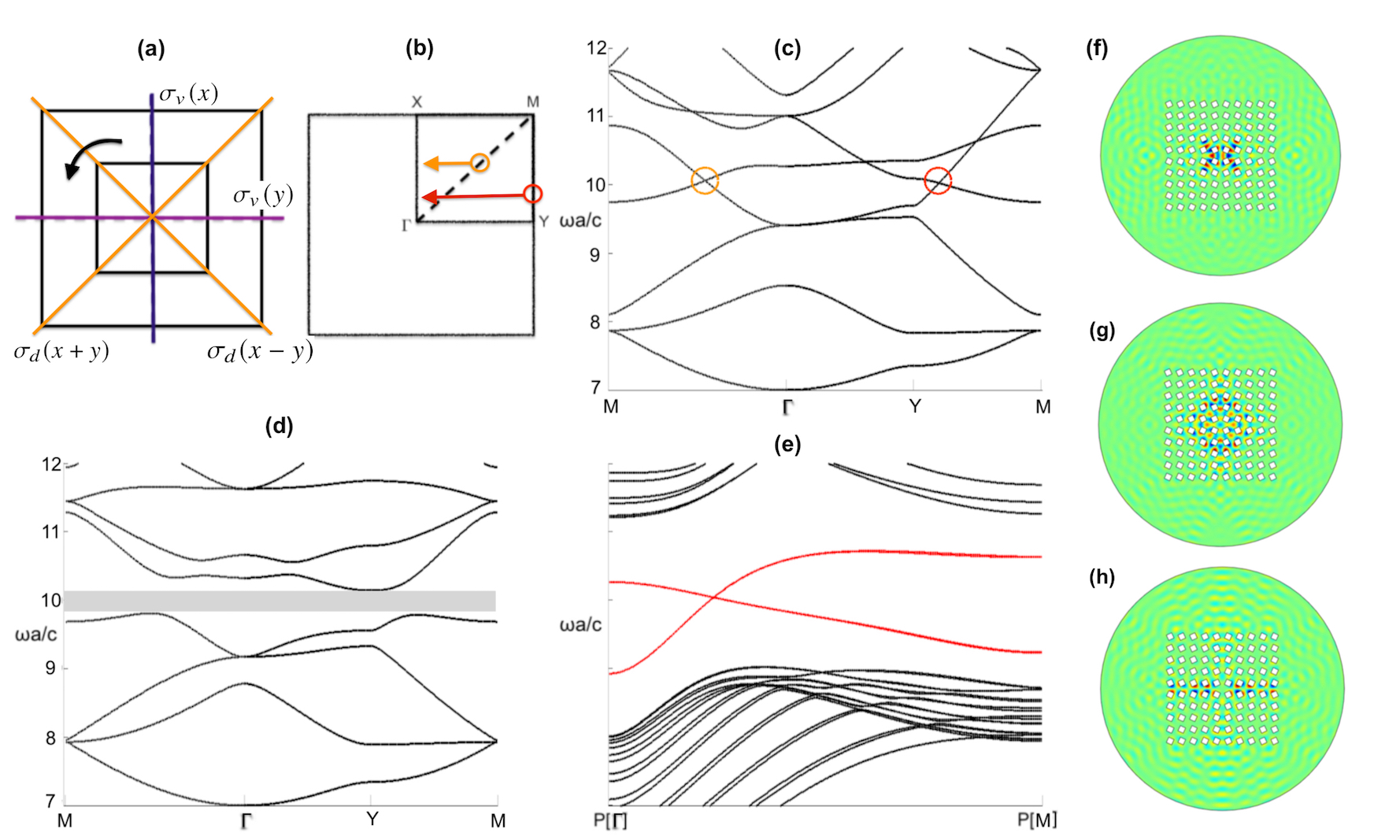
The computed edge states formed via the stacking of one perturbed medium above its reflectional twin, Fig. 6(b), are shown in Fig. 10(e). The gapless nature of the states is indicative of their underlying topological nature. For hexagonal systems, ZLMs with distinguishable valley degrees of freedom exist for every propagation direction other than for the armchair [56]; the armchair termination superposes the valleys, thereby coupling them and making them less robust; this coupling results in band repulsion and gapped edge states [71].